EP0005937B1 - Stützrad für ein Raupenfahrzeug - Google Patents
Stützrad für ein Raupenfahrzeug Download PDFInfo
- Publication number
- EP0005937B1 EP0005937B1 EP79300842A EP79300842A EP0005937B1 EP 0005937 B1 EP0005937 B1 EP 0005937B1 EP 79300842 A EP79300842 A EP 79300842A EP 79300842 A EP79300842 A EP 79300842A EP 0005937 B1 EP0005937 B1 EP 0005937B1
- Authority
- EP
- European Patent Office
- Prior art keywords
- wheel
- rim
- disc
- wheel element
- track
- Prior art date
- Legal status (The legal status is an assumption and is not a legal conclusion. Google has not performed a legal analysis and makes no representation as to the accuracy of the status listed.)
- Expired
Links
Images

Classifications
-
- B—PERFORMING OPERATIONS; TRANSPORTING
- B62—LAND VEHICLES FOR TRAVELLING OTHERWISE THAN ON RAILS
- B62D—MOTOR VEHICLES; TRAILERS
- B62D55/00—Endless track vehicles
- B62D55/08—Endless track units; Parts thereof
- B62D55/14—Arrangement, location, or adaptation of rollers
- B62D55/145—Rollers with replaceable wear rings or rims
Definitions
- This invention relates to wheels and in particular to wheels for track-laying vehicles, that is vehicles which travel on endless tracks which extend beneath a number of support wheels and around one or more traction wheels.
- the invention is concerned with the constructional details of support wheels for track laying vehicles.
- CH-A-542,089 discloses an aluminium track roller for tracked vehicles wherein each roller element comprises a central disc portion formed integrally with a rim cantilevered axially outwardly from one edge of the disc to provide adjacent parts of the disc and rim of L-shape.
- each roller element comprises a central disc portion formed integrally with a rim cantilevered axially outwardly from one edge of the disc to provide adjacent parts of the disc and rim of L-shape.
- Such a construction necessitates a large amount of material to be present at the transition zone from the disc to the rim and/or the provision of reinforcing ribs at the disc/rim transition zone, otherwise insufficient strength is imparted to the rim.
- CA-A-959,742 discloses a single piece wheel of T-shape in radial cross section but this wheel is intended for use in material handling equipment such as trucks or carts employed over short distances on smooth surfaces. However even in this construction it is still found necessary to provide stiffening ribs in the disc.
- a support wheel for a track laying vehicle comprising a pair of one-piece wheel elements secured together, each wheel element comprising a disc formed integrally with a rim and characterised in that the adjacent parts of the disc and rim of each wheel element jointly define a T-shape in radial cross section, the disc being of dished configuration with the centre part of the disc extending axially of the wheel element beyond one of the edges of the rim; the two wheel elements being secured together at the centre part of the discs thereof to define a continuous groove between the edges of the rims for accommodating the horns of a track to be supported on the rims.
- each wheel element By arranging the adjacent parts of the disc and rim in each wheel element to be of T-shape so that the wheel disc merges with the rim in the central portion of the rim, it is possible more equally to balance the manner in which the disc is loaded by the rim as compared with the wheel arrangements of CH-A-542,089 in which the disc and rim merge at or adjacent one of the edges of the rim. Also, the T-shape of wheel in accordance with the invention, which effectively provides axially outwardly extending rim portions cantilevered from either side of the disc, enables an equivalent stiffness of wheel to be provided to that of Swiss Patent 542,089 whilst using much lighter gauge metal throughout.
- the edge of the rim adjacent the track horns is spaced an appreciable distance from the zone where the disc and rim merge.
- an appreciable amount of wear can take place at the edge of the rim adjacent the horns without the strength of the wheel being greatly affected. This is an important consideration as the wear at this edge of the rim, due to contact with the track horns, can be severe.
- each wheel element is made from an alloy of aluminium and/or magnesium.
- alloys which are aluminium, magnesium, zinc alloys, specified by the American Aluminum Association may conveniently be used. Reduction in the weight of the wheels of a track laying vehicle reduces the inertia forces generated in the vehicle suspension system and enables the vehicle to travel faster over rough ground.
- a support wheel in accordance with the invention may be provided with a solid rubber tyre which is bonded onto the outer peripheral surface of the rim.
- the rim may be cylindrical or may be tapered so that the outer peripheral surface of the rim is closer to the rotary axis of the wheel at the edges of the rim than at the centre of the rim.
- the edge of the rim of each wheel element which will be positioned adjacent to the track horns may be reinforced to resist the wear referred to above.
- means for resisting wear may be embedded in the appropriate rim edge, attached to the rim edge as replaceable strips or studs, or the edge may be overlaid with a hard facing.
- embedded wear resisting means are a steel hoop or wires, metal carbide filaments and/or particles, or metal carbide textiles.
- rivet or screw attached replaceable wear strips or steel or other metal or metal carbides may be used. Studs of similar material to the wear strips referred to above can also be employed. If an overlaid hard facing is employed this can be provided by applying a hard material using flame or plasma spraying or electroplating.
- Each wheel element may also include radially extending reinforcing ribs which extend on one or both sides of the disc between the disc and rim.
- Each wheel element is also preferably provided with an accurately formed and positioned cylindrical datum surface which is concentric with the rotary axis of the wheel element and which is used to locate the wheel element while the tyre is moulded onto the rim.
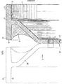
- this shows a one piece aluminium wheel element for a track-laying vehicle comprising a dished disc portion 10 and a rim portion 12.
- the disc merges into the rim substantially in the axially central zone 14 of the rim so that the adjacent portions of the disc and rim together are of T-shape.
- the centre portion 16 of the disc 10 extends axially beyond the edge 18 of the rim 12 so that if a second similar wheel element 20, shown in dotted lines in Figure 1, is secured to the wheel element 11 so that the wheel elements are in back-to-back configuration a continuous, circumferentially-extending groove is provided between the two wheel elements into which the horns on the track (not shown) are arranged to extend, and guide the track beneath the wheels.
- Bolt holes 22 are provided in the centre portion 16 for securing the two wheel elements together and also for securing them to a hub of the vehicle.
- the outer peripheral surfaces of the rims are cylindrical as shown at 24. This assists in locating a solid rubber tyre (not shown) on each rim.
- the tyre is moulded in situ on the rim, the wheel element being Icoated in a mould during this moulding process using a cylindrical datum surface 26 on the inner side of the rim or the surface 27 adjacent the centre of the disc, in either case the surface being accurately located on the wheel element about the rotary axis thereof.
- Each wheel element is formed from molten metal.
- the surfaces 24 and 26 and 27 may be machined on the wheel element after forming and prior to the moulding of the rubber tyre on the rim.
- each wheel element may be reinforced by radially extending ribs on either side of the disc and which extend between the disc and rim portions of the wheel element. For example, such ribs may extend across the shaded portion X of Figure 1.
Landscapes
- Engineering & Computer Science (AREA)
- Chemical & Material Sciences (AREA)
- Combustion & Propulsion (AREA)
- Transportation (AREA)
- Mechanical Engineering (AREA)
- Tires In General (AREA)
- Braking Arrangements (AREA)
Claims (3)
Applications Claiming Priority (2)
| Application Number | Priority Date | Filing Date | Title |
|---|---|---|---|
| GB23456/78A GB1595270A (en) | 1978-05-26 | 1978-05-26 | Support wheels for track-laying vehicles |
| GB2345678 | 1978-05-26 |
Publications (2)
| Publication Number | Publication Date |
|---|---|
| EP0005937A1 EP0005937A1 (de) | 1979-12-12 |
| EP0005937B1 true EP0005937B1 (de) | 1983-05-25 |
Family
ID=10195928
Family Applications (1)
| Application Number | Title | Priority Date | Filing Date |
|---|---|---|---|
| EP79300842A Expired EP0005937B1 (de) | 1978-05-26 | 1979-05-16 | Stützrad für ein Raupenfahrzeug |
Country Status (8)
| Country | Link |
|---|---|
| EP (1) | EP0005937B1 (de) |
| JP (1) | JPS54157916A (de) |
| AU (1) | AU524064B2 (de) |
| CA (1) | CA1101912A (de) |
| DE (1) | DE2965490D1 (de) |
| GB (1) | GB1595270A (de) |
| IN (1) | IN151107B (de) |
| ZA (1) | ZA792527B (de) |
Families Citing this family (4)
| Publication number | Priority date | Publication date | Assignee | Title |
|---|---|---|---|---|
| ATE9878T1 (de) * | 1980-03-12 | 1984-11-15 | Gkn Technology Limited | Rad eines raupenketten-fahrzeugs. |
| DE3221756C2 (de) * | 1982-06-09 | 1985-08-08 | Krauss-Maffei AG, 8000 München | Laufrolle für ein Gleiskettenfahrwerk |
| DE8710631U1 (de) * | 1987-08-03 | 1987-10-08 | Bernex Oberflächenmetallurgie GmbH, 4018 Langenfeld | Laufrolle |
| WO2015063547A1 (en) * | 2013-11-01 | 2015-05-07 | Anurath Abeyratne Malagalage | A light weight rim for idler and bogie wheels of a heavy duty tracked vehicle made of thermoplastic resin |
Family Cites Families (4)
| Publication number | Priority date | Publication date | Assignee | Title |
|---|---|---|---|---|
| FR2044962A5 (de) * | 1969-05-28 | 1971-02-26 | Magnesium Ind | |
| JPS4813851U (de) * | 1971-06-23 | 1973-02-16 | ||
| CH542089A (de) * | 1972-09-13 | 1973-09-30 | Fischer Ag Georg | Laufrolle für Raupenfahrzeuge |
| CA959742A (en) * | 1972-11-29 | 1974-12-24 | Maurice Lacerte | Solid tire wheel |
-
1978
- 1978-05-26 GB GB23456/78A patent/GB1595270A/en not_active Expired
-
1979
- 1979-05-16 DE DE7979300842T patent/DE2965490D1/de not_active Expired
- 1979-05-16 EP EP79300842A patent/EP0005937B1/de not_active Expired
- 1979-05-21 IN IN353/DEL/79A patent/IN151107B/en unknown
- 1979-05-22 AU AU47287/79A patent/AU524064B2/en not_active Expired
- 1979-05-23 ZA ZA792527A patent/ZA792527B/xx unknown
- 1979-05-25 JP JP6491279A patent/JPS54157916A/ja active Pending
- 1979-05-25 CA CA328,366A patent/CA1101912A/en not_active Expired
Also Published As
| Publication number | Publication date |
|---|---|
| GB1595270A (en) | 1981-08-12 |
| ZA792527B (en) | 1980-08-27 |
| CA1101912A (en) | 1981-05-26 |
| IN151107B (de) | 1983-02-19 |
| JPS54157916A (en) | 1979-12-13 |
| EP0005937A1 (de) | 1979-12-12 |
| AU524064B2 (en) | 1982-08-26 |
| AU4728779A (en) | 1979-11-29 |
| DE2965490D1 (en) | 1983-07-07 |
Similar Documents
| Publication | Publication Date | Title |
|---|---|---|
| US4472164A (en) | Sprocket wheel | |
| US3843202A (en) | Solid tire wheel | |
| US3709561A (en) | Brake and wheel assembly for motorcycles and the like | |
| US5499864A (en) | Bicycle wheel rims | |
| US4363347A (en) | Motor vehicle wheel | |
| CA1237162A (en) | Tracked vehicle road wheel | |
| US4538860A (en) | Wear resistant wheel for track laying vehicle | |
| US4592595A (en) | Wheel construction of shopping carts and the like | |
| US10525769B2 (en) | Reinforced axle joint | |
| US2734778A (en) | Reinforced tire supporting member | |
| US5433511A (en) | Cast wheel reinforced with a metal matrix composite | |
| EP0005937B1 (de) | Stützrad für ein Raupenfahrzeug | |
| US3025898A (en) | Safety wheel rim | |
| US4035028A (en) | Wheel assemblies and components | |
| US3790219A (en) | Wheel | |
| US4425008A (en) | Wheel for a tracklaying vehicle | |
| EP0326876B1 (de) | Vorrichtung zum Kühlen und Ausleeren von Gussstücken aus Sandformen | |
| EP0035913B1 (de) | Rad eines Raupenketten-Fahrzeugs | |
| WO2003037652A1 (en) | Full face fabricated vehicle wheel and method for producing same | |
| US2818303A (en) | Wheel | |
| US3302273A (en) | Method of making composite vehicle wheel | |
| US10773547B2 (en) | Reinforced vehicle wheel rim and fabricated vehicle wheel and method for producing the same | |
| US20240227439A1 (en) | Multipiece Road Wheel | |
| EP3947120B1 (de) | Mehrteiliges strassenrad | |
| US2091602A (en) | Composite wheel |
Legal Events
| Date | Code | Title | Description |
|---|---|---|---|
| PUAI | Public reference made under article 153(3) epc to a published international application that has entered the european phase |
Free format text: ORIGINAL CODE: 0009012 |
|
| AK | Designated contracting states |
Designated state(s): BE CH DE FR IT LU NL SE |
|
| 17P | Request for examination filed | ||
| ITF | It: translation for a ep patent filed | ||
| GRAA | (expected) grant |
Free format text: ORIGINAL CODE: 0009210 |
|
| AK | Designated contracting states |
Designated state(s): BE CH DE FR IT LU NL SE |
|
| ET | Fr: translation filed | ||
| REF | Corresponds to: |
Ref document number: 2965490 Country of ref document: DE Date of ref document: 19830707 |
|
| PLBE | No opposition filed within time limit |
Free format text: ORIGINAL CODE: 0009261 |
|
| STAA | Information on the status of an ep patent application or granted ep patent |
Free format text: STATUS: NO OPPOSITION FILED WITHIN TIME LIMIT |
|
| 26N | No opposition filed | ||
| ITTA | It: last paid annual fee | ||
| EPTA | Lu: last paid annual fee | ||
| EAL | Se: european patent in force in sweden |
Ref document number: 79300842.6 |
|
| PGFP | Annual fee paid to national office [announced via postgrant information from national office to epo] |
Ref country code: FR Payment date: 19970513 Year of fee payment: 19 |
|
| PGFP | Annual fee paid to national office [announced via postgrant information from national office to epo] |
Ref country code: SE Payment date: 19970516 Year of fee payment: 19 |
|
| PGFP | Annual fee paid to national office [announced via postgrant information from national office to epo] |
Ref country code: CH Payment date: 19970522 Year of fee payment: 19 |
|
| PGFP | Annual fee paid to national office [announced via postgrant information from national office to epo] |
Ref country code: DE Payment date: 19970523 Year of fee payment: 19 |
|
| PGFP | Annual fee paid to national office [announced via postgrant information from national office to epo] |
Ref country code: NL Payment date: 19970529 Year of fee payment: 19 |
|
| PGFP | Annual fee paid to national office [announced via postgrant information from national office to epo] |
Ref country code: LU Payment date: 19970624 Year of fee payment: 19 |
|
| PGFP | Annual fee paid to national office [announced via postgrant information from national office to epo] |
Ref country code: BE Payment date: 19970627 Year of fee payment: 19 |
|
| PG25 | Lapsed in a contracting state [announced via postgrant information from national office to epo] |
Ref country code: LU Free format text: LAPSE BECAUSE OF NON-PAYMENT OF DUE FEES Effective date: 19980516 |
|
| PG25 | Lapsed in a contracting state [announced via postgrant information from national office to epo] |
Ref country code: SE Free format text: LAPSE BECAUSE OF NON-PAYMENT OF DUE FEES Effective date: 19980517 |
|
| PG25 | Lapsed in a contracting state [announced via postgrant information from national office to epo] |
Ref country code: FR Free format text: LAPSE BECAUSE OF NON-PAYMENT OF DUE FEES Effective date: 19980531 Ref country code: CH Free format text: LAPSE BECAUSE OF NON-PAYMENT OF DUE FEES Effective date: 19980531 Ref country code: BE Free format text: LAPSE BECAUSE OF NON-PAYMENT OF DUE FEES Effective date: 19980531 |
|
| BERE | Be: lapsed |
Owner name: GKN GROUP SERVICES LTD Effective date: 19980531 |
|
| PG25 | Lapsed in a contracting state [announced via postgrant information from national office to epo] |
Ref country code: NL Free format text: LAPSE BECAUSE OF NON-PAYMENT OF DUE FEES Effective date: 19981201 |
|
| REG | Reference to a national code |
Ref country code: CH Ref legal event code: PL |
|
| EUG | Se: european patent has lapsed |
Ref document number: 79300842.6 |
|
| NLV4 | Nl: lapsed or anulled due to non-payment of the annual fee |
Effective date: 19981201 |
|
| PG25 | Lapsed in a contracting state [announced via postgrant information from national office to epo] |
Ref country code: DE Free format text: LAPSE BECAUSE OF NON-PAYMENT OF DUE FEES Effective date: 19990302 |
|
| REG | Reference to a national code |
Ref country code: FR Ref legal event code: ST |