EP0006111B1 - Pierre abrasive pour outil abrasif expansible - Google Patents
Pierre abrasive pour outil abrasif expansible Download PDFInfo
- Publication number
- EP0006111B1 EP0006111B1 EP79100972A EP79100972A EP0006111B1 EP 0006111 B1 EP0006111 B1 EP 0006111B1 EP 79100972 A EP79100972 A EP 79100972A EP 79100972 A EP79100972 A EP 79100972A EP 0006111 B1 EP0006111 B1 EP 0006111B1
- Authority
- EP
- European Patent Office
- Prior art keywords
- helical
- arbor
- abrading
- helical element
- coils
- Prior art date
- Legal status (The legal status is an assumption and is not a legal conclusion. Google has not performed a legal analysis and makes no representation as to the accuracy of the status listed.)
- Expired
Links
Images

Classifications
-
- B—PERFORMING OPERATIONS; TRANSPORTING
- B24—GRINDING; POLISHING
- B24B—MACHINES, DEVICES, OR PROCESSES FOR GRINDING OR POLISHING; DRESSING OR CONDITIONING OF ABRADING SURFACES; FEEDING OF GRINDING, POLISHING, OR LAPPING AGENTS
- B24B33/00—Honing machines or devices; Accessories therefor
- B24B33/08—Honing tools
- B24B33/085—Honing tools in which the honing element consists of a deformable body
Definitions
- This invention relates to an abrading element for use in the sizing and finishing of holes and also relates to an abrading tool incorporating the abrading element.
- Abrading tools are used to size and surface finish holes during a machining operation in which an abrasive insert of the tool is inserted into the hole and rotated to machine the hole.
- a relatively small amount of material stock is usually removed during this type of machining operation since the abrasive grit size is normally sufficiently small so as to provide a smooth surface finish.
- abrading tool which is disclosed by the prior art utilizes an abrasive member and a carbide shoe or utilizes two or more abrasive members mounted for radial movement with respect to each other so that the tool can be inserted within the hole and then expanded to perform the machining operation as the tool is rotated. Machining takes place within the hole as the expanded tool is rotated.
- Another type of abrading tool incorporates a sleeve having an axial slit which has a circumferential component of about 360 degrees or less.
- An abrasive or lapping compound can be supplied to the sleeve during tool rotation to perform abrading by what is referred to as lapping.
- an abrasive grit can be secured to the sleeve to perform the abrading as the tool is rotated. Mounting of the sleeve on a tapered arbor and axial positioning therealong allows the diameter of the sleeve to be controlled as the width of the slit in the sleeve varies according to the axial position.
- DE-C-3 500 83 discloses a helical element in the form of a wire or the like disposed about a spindle for lapping bores.
- the helical element can be axially stretched or axially compressed to vary the outside diameter thereof or it can be wound or unwound to achieve a similar result, one end of the helix being fixed to the spindle and the other end being secured to a nut threadedly engaged with the spindle.
- the abrasive agent is received between the individual turns of the helix.
- U.S.-A-3,462,887 discloses an abrasive coated lap which comprises an annular body having a uniformly tapered internal opening and a straight cylindrical lap surface coated with abrasive material.
- the annular body has a through slot construction through its annular wall preferably extending the length of the lap in the form of a helical slot which spirals about 360 degrees from one end of the lap to the other.
- the lap is carried on a tapered arbor and is radially expanded to a larger uniform circumference by tapping it on to the arbor on which it is frictionally held with the slot expanded.
- the abrading tools are of precise sizes so that the holes are machined to the required diameters. Also, the abrasive surfaces of rotatable abrading tools wear during use. Some provision for compensating for such wear is advantageous in order to increase tool life during which holes can be finished and sized to the same diameter.
- the object of the invention is to provide an improved abrading element for use in the sizing and finishing of holes.
- an abrading element for attachment to a tapered rotary arbor of a machine, said abrading element including a helical element having an axial outer surface coated with an abrasive material and an inner axial surface complementary to that of the tapered arbor which progressively increases in diameter from one axial end thereof to the other to permit radial expansion of the helical element by the tapered arbor to a determined selected diameter characterised in that the helical element is composed of coils the respective coils of which are in face to face abutting relationship with adjacent coils of the helical element to inhibit axial compression of the helical element.
- an abrading element for attachment to a tapered rotary arbor of a machine, said abrading element including a helical element having an axial outer surface coated with an abrasive material and an inner axial surface complementary to that of the tapered arbor which progressively increases in diameter from one axial end thereof to the other to permit radial expansion of the helical element by the tapered arbor to a determined selected diameter characterised in that the helical element is composed of coils and a helical spacer of incompressible material is interposed between adjacent coils of the helical element which coils are in abutting relationship with the interposed turns of the helical spacer to inhibit axial compression of the helical element.
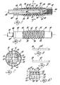
- an expandable abrading tool constructed according to the invention is indicated collectively by reference numeral 20 and includes a tapered arbor 22 and an abrading element 24 which is mounted on the arbor.
- Tool arbor 22 has a central axis of rotation and includes an outer surface 26 of a frustoconical shape which has a smaller size at its right end than at its left end.
- Abrading element 24 includes a helical element 28 having coils 30 which receive the arbor and engage the outer arbor surface 26.
- An outer abrasive strip 32 on the coils 30 has a helical shape that extends between the opposite ends of the insert.
- a helical spacer that is wound about the arbor between the coils 30 of the helical element includes a metal spring 34 that engages the outer arbor surface 26 in a radial direction and that also engages the coils in an axial direction so as to prevent movement of the coils toward each other and maintain the helical element axially incompressible.
- a helical spacer portion 36 (FIGURE 1) of electrically nonconductive material fills the void between the coils radially outward from the spring 34 and is located between the abrasive strip 32 on adjacent coils. The portion of the abrasive strip 32 on each coil is spaced from the abrasive strip portion on the adjacent coils as a result of the spacer 34, 36.
- a threaded portion 38 at the smaller right end of the arbor 22 is shown in FIGURE 1 and receives a nut 40 which is axially seated against the right end of the abrasive insert 24.
- a threaded portion 42 at the larger left end of the arbor 22 receives nut 44 that is seated against the left end of the abrasive insert 24.
- a lock nut 46 also is received by the threaded portion 42 and is engaged with the nut 44 in order to provide a locked condition thereof on the arbor.
- nuts 46 and 44 are threaded to the left, and then nut 40 is threaded to the left to move the abrasive insert 24 axially to the left along the tapered arbor, and thus expand the abrasive insert in a radial direction.
- the nuts can be threaded along the arbor to move the insert 24 to the right or to the left along the arbor to increase or decrease the coil diameters in order to initially size the abrasive insert for use.
- Nuts 40, 44 and 46 as well as the arbor threaded portions thus provide a means for adjustably positioning the abrasive insert 24 along the arbor 22.
- Abrasive strip 32 preferably includes diamond or borazon grits which are secured to the coils 30 by a plating process wherein a matrix of nickel or another suitable metal is plated on the coils to secure the abrasive grits.
- the electrically non-conductive outer spacer portion 36 prevents the metal plating from forming any bridging portions between adjacent coils, thus ensuring that the coils are not interconnected by the plating and that they are thus free to slide circumferentially with respect to each other as the element 24 is moved axially of the arbor.
- the abrading element 24 includes a leading end 48 which is tapered with a frustoconical shape, and also includes a trailing end 50 which is likewise tapered with a frustoconical shape.
- leading end 48 of the rotating tool 20 is inserted within a hole to be machined, the tapered shape of the leading end pilots the tool during the initial movement of the tool into the hole, and thus ensures proper alignment.
- the tapered trailing end 50 of the element guides the tool to prevent damage to the finished surface of the hole as the rotating tool is pulled out of the hole upon completion of the machining operation.
- Tool 20 shown in FIGURES 1 and 2 is preferably rotated in a clockwise direction when viewed from the right looking toward the left, so that the resultant force vector F (FIGURE 2) on each coil acts in a direction to wind the coils more tightly about the arbor 22 and thereby cause a locking action of the element 24 on the arbor to prevent rotation of the element 24, relatively to the arbor.
- F resultant force vector
- a modification of the abrading element 24 includes a leading tapered end 48 having an end coil with an inwardly bent portion 52, which is received in an axially extending slot 54 in the arbor adjacent the threaded portion 38. Engagement of the coil end portion 52 within the slot 54 prevents rotation of the element 24 relatively to the arbor during use of the tool. Upon movement of the element 24 to the left along the arbor, the end portion 52 of the coil will slide within the slot 54 in an axial direction, so that the element 24 can be expanded in the manner previously described to compensate for wear of the abrasive strip 32.
- Arbor 22 of the tool 20a includes an axial passage 56 that extends along the axis of rotation of the tool. Radial passages 58 extend outwardly from the central passage 56, and communicate with longitudinally extending passages 60 in the outer arbor surface 26. Spacer spring 34 is coated with a suitable non-conductive covering so that the plating of the abrasive strip 32 on the coils 30 does not result in any plated surfaces that bridge between adjacent coils.
- Abrasive insert 24 of the tool 20a includes radial passages which are defined by axial formations 62 in the coils 30.
- a suitable lubricating or coolant fluid is fed through the arbor passages 56, 58, and 60 of the arbor, and is then fed through the radial passages defined by the formations 62 outwardly to the abrasive strip 32. Particles resulting from a machining operation can flow with the lubricating fluid along the helical space between the coils so that the particles are removed from the hole which is being machined.
- the lubricating fluid is continually supplied to the tool from a suitable pump and is preferably filtered so as to continuously remove the particles from the fluid.
- the helical element 28 of the embodiments shown in FIGURES 1 to 6 is preferably made by winding square metal wire around a tapered mandrel of identical taper to that of the arbor.
- the metal wire can be crimped before the winding as shown in FIGURE 8 so as to define the formations 62 for supplying the lubricating fluid on both radial faces of each coil.
- the formations 62 can be formed as shown in FIGURE 9 on only one radial face of the wire.
- FIGURE 10 another embodiment of the tool is indicated by reference numeral 20b, the tool being of a construction similar to the other two embodiments such that like reference numerals are utilized and much of the previous description is also applicable to this tool except as will be noted.
- the coils 30 of the abrading element of tool 20b are engaged axially with each other, as opposed to being axially spaced as in the other embodiments.
- Coils 30 include a groove 64 that cooperatively defines a helical space along the element between that portion of each of the coils which is adjacent the abrasive strip.
- a suitable electrically non-conductive filler 66 is received within the groove 64 so as to prevent the plating which secures the abrasive to the coils from bridging between adjacent coils.
- Coils 30 are thus free to move circumferentially with respect to each other as the coil diameter is increased or decreased.
- the filler 66 has a smaller diameter than that of the abrasive strip 32, so as to provide a path along which the particles can be removed from the hole being machined.
- Coils 30 also include formations 62 which feed fluid supplied from the arbor 22 to the abrasive strip for cooling and particle removal during a machining operation. The fluid flows out through the groove 64 at spaced voids in the filler 66.
- the helical element of each of the embodiments which has been described is first wound on a tapered mandrel from a suitable wire in the manner previously described, and the helical element is then ground to define the tapered ends 48 and 50 for guiding the tool.
- the coils 30 are also ground between the tapered ends so that the mounted insert has an axial portion intermediate the tapered ends which is of generally constant outer diameter.
- the ground helical element so formed is of progressively increasing thickness T starting at a point just to the right of the trailing end 50 and moving toward the leading tapered end 48 of the element.
- the coils 30 are each expanded by the same amount so that the outer diameter of the intermediate portion is increased to its original diameter in order to compensate for the wear of the abrasive strip 32.
- the leading and trailing ends 48 and 50 of the helical element are expanded by the movement of the element and compensation for wear of the abrasive thus takes place.
Landscapes
- Engineering & Computer Science (AREA)
- Mechanical Engineering (AREA)
- Polishing Bodies And Polishing Tools (AREA)
Claims (12)
Applications Claiming Priority (2)
| Application Number | Priority Date | Filing Date | Title |
|---|---|---|---|
| US05/897,626 US4199903A (en) | 1978-04-19 | 1978-04-19 | Expandable abrading tool and abrasive insert thereof |
| US897626 | 1978-04-19 |
Publications (2)
| Publication Number | Publication Date |
|---|---|
| EP0006111A1 EP0006111A1 (fr) | 1980-01-09 |
| EP0006111B1 true EP0006111B1 (fr) | 1982-09-01 |
Family
ID=25408147
Family Applications (1)
| Application Number | Title | Priority Date | Filing Date |
|---|---|---|---|
| EP79100972A Expired EP0006111B1 (fr) | 1978-04-19 | 1979-03-30 | Pierre abrasive pour outil abrasif expansible |
Country Status (5)
| Country | Link |
|---|---|
| US (1) | US4199903A (fr) |
| EP (1) | EP0006111B1 (fr) |
| JP (1) | JPS54140292A (fr) |
| CA (1) | CA1081467A (fr) |
| DE (1) | DE2963599D1 (fr) |
Families Citing this family (18)
| Publication number | Priority date | Publication date | Assignee | Title |
|---|---|---|---|---|
| DE3144810A1 (de) * | 1981-11-11 | 1983-05-19 | Löhr & Bromkamp GmbH, 6050 Offenbach | "schleifstift" |
| US4437267A (en) * | 1982-02-24 | 1984-03-20 | Ex-Cell-O Corporation | Single pass sizing tool and machine including wear compensation means |
| DE3336626A1 (de) * | 1983-10-08 | 1985-04-25 | Peter 7442 Neuffen Nagel | Honwerkzeug |
| JPS6119570A (ja) * | 1984-07-05 | 1986-01-28 | Tsukada Hiroyuki | 切削具 |
| US4843768A (en) * | 1986-12-01 | 1989-07-04 | B & J Manufacturing Company | Abrading apparatus and process for making the same |
| DE3642258A1 (de) * | 1986-12-11 | 1988-06-23 | Teves Gmbh Alfred | Honwerkzeug |
| US5081797A (en) * | 1988-11-09 | 1992-01-21 | Acme Manufacturing | Integrated buffing and grinding system |
| US5119929A (en) * | 1988-11-09 | 1992-06-09 | Acme Manufacturing | Integrated buffing and grinding system |
| JPH0322863U (fr) * | 1989-07-14 | 1991-03-11 | ||
| EP0413847A1 (fr) * | 1989-08-25 | 1991-02-27 | Maschinenfabrik Gehring GmbH & Co. | Outil de rodage pour l'usinage d'alésages, en particulier d'alésages de cylindres |
| DE69935084T2 (de) * | 1998-07-31 | 2007-11-15 | Saint-Gobain Abrasives, Inc., Worcester | Drehende Abrichtrolle enthaltende abschleifende Einsätze |
| RU2155124C1 (ru) * | 1999-01-19 | 2000-08-27 | Орловский государственный технический университет | Головка для обработки внутренней цилиндрической поверхности |
| US6634719B1 (en) | 2001-08-15 | 2003-10-21 | Snotech, Inc. | Ice scruffer |
| WO2011163542A1 (fr) * | 2010-06-25 | 2011-12-29 | Ksw Technology Inc. | Outil et procédés et appareil associés |
| US9789581B2 (en) * | 2010-10-18 | 2017-10-17 | Sunnen Products Company | Bore finishing tool |
| JP6227431B2 (ja) * | 2014-01-31 | 2017-11-08 | コマツNtc株式会社 | 内周面加工用工具 |
| CA2969404C (fr) * | 2014-12-12 | 2019-06-25 | Mitsubishi Heavy Industries Machine Tool Co., Ltd. | Outil de fraisage et procede de fabrication pour ce dernier |
| CN105904287B (zh) * | 2016-07-01 | 2017-12-26 | 东北大学 | 一种加工狭窄槽系叶轮的方法、磨头及其制备方法 |
Family Cites Families (14)
| Publication number | Priority date | Publication date | Assignee | Title |
|---|---|---|---|---|
| DE350083C (de) * | 1922-03-16 | Adolf Pochwadt | Schleifwerkzeug fuer koerniges Schleifmittel und Innenzylinderflaechen | |
| DE241289C (fr) * | ||||
| DE196154C (fr) * | ||||
| DE360872C (de) * | 1921-05-24 | 1922-10-07 | Alfred Weisheit | Schleifvorrichtung zum Ausschleifen geschliffener Glaszylinder |
| US1792800A (en) * | 1930-03-15 | 1931-02-17 | Conrad F Birgbauer | Lapping device |
| US1865229A (en) * | 1930-03-15 | 1932-06-28 | Conrad F Birgbauer | Lapping device |
| US2115210A (en) * | 1935-01-22 | 1938-04-26 | Gen Abrasive Company Inc | Abrasive wheel |
| GB563199A (en) * | 1943-02-03 | 1944-08-02 | Douglas Taylor | Improvements in means for honing or lapping cylindrical bores |
| DE958005C (de) * | 1953-06-09 | 1957-02-14 | Lothar Stahl Fa | Honwerkzeug |
| US2725694A (en) * | 1953-11-30 | 1955-12-06 | Bert B Lukens | Chuck for holding abrasive elements in web form |
| US3324607A (en) * | 1964-08-13 | 1967-06-13 | Super Cut | Rotary grinding tool with interrupted abrasive helicoid |
| US3462887A (en) * | 1966-04-25 | 1969-08-26 | Arthur J Hackman Jr | Precision surface abrading |
| US3717956A (en) * | 1970-12-11 | 1973-02-27 | A Keatts | Expanding lap arbor |
| US3951619A (en) * | 1973-05-11 | 1976-04-20 | Frangipane Joseph G | Method of making a grinding wheel |
-
1978
- 1978-04-19 US US05/897,626 patent/US4199903A/en not_active Expired - Lifetime
- 1978-10-31 CA CA315,207A patent/CA1081467A/fr not_active Expired
-
1979
- 1979-03-30 EP EP79100972A patent/EP0006111B1/fr not_active Expired
- 1979-03-30 DE DE7979100972T patent/DE2963599D1/de not_active Expired
- 1979-04-19 JP JP4735679A patent/JPS54140292A/ja active Granted
Also Published As
| Publication number | Publication date |
|---|---|
| JPS54140292A (en) | 1979-10-31 |
| US4199903A (en) | 1980-04-29 |
| CA1081467A (fr) | 1980-07-15 |
| DE2963599D1 (en) | 1982-10-28 |
| EP0006111A1 (fr) | 1980-01-09 |
| JPS5540389B2 (fr) | 1980-10-17 |
Similar Documents
| Publication | Publication Date | Title |
|---|---|---|
| EP0006111B1 (fr) | Pierre abrasive pour outil abrasif expansible | |
| EP0005003B1 (fr) | Outil abrasif expansible | |
| US5022196A (en) | Expandable honing tool | |
| CN104875082B (zh) | 圆柱形磨削工艺及由此工艺所得的磨削完工部件 | |
| KR102165842B1 (ko) | 드릴 구멍을 생성하기 위한 천공 기구 및 방법 | |
| JP4024122B2 (ja) | ピストンエンジン用のシリンダライナーの製造方法 | |
| JPS6242723B2 (fr) | ||
| EP1118430B1 (fr) | Machine de rectification et procédé d'usinage | |
| DE3509340A1 (de) | Verfahren und vorrichtung zur endbearbeitung von stirnflaechenkollektoren | |
| US4197680A (en) | Precision honing mandrel | |
| US6139414A (en) | Flexible tool for plateauing a surface | |
| EP3582931B1 (fr) | Outil de finissage et procédé d'usinage de précision reposant sur l'utilisation de l'outil de finissage | |
| GB2272659A (en) | On edge honing devices | |
| US4044508A (en) | Adjustable honing template | |
| US4467566A (en) | Valve seat grinding device and tool for using same | |
| US5846126A (en) | Outside diameter finishing tool and method of making the same | |
| JP3613009B2 (ja) | ホーニングヘッド | |
| GB2054421A (en) | Honing device | |
| EP0389637B1 (fr) | Outil aleseur a electrodeposition | |
| CN107009259A (zh) | 一种螺纹调节的铰珩杆 | |
| US4173852A (en) | Expandable tool including cutting section and pilot | |
| US4254591A (en) | Internal lapping tool | |
| US6080053A (en) | Outside diameter finishing tool and method of making the same | |
| US4519125A (en) | Sucker rod coupling manufacturing system | |
| US3717956A (en) | Expanding lap arbor |
Legal Events
| Date | Code | Title | Description |
|---|---|---|---|
| PUAI | Public reference made under article 153(3) epc to a published international application that has entered the european phase |
Free format text: ORIGINAL CODE: 0009012 |
|
| AK | Designated contracting states |
Designated state(s): DE FR GB IT |
|
| 17P | Request for examination filed | ||
| ITF | It: translation for a ep patent filed | ||
| GRAA | (expected) grant |
Free format text: ORIGINAL CODE: 0009210 |
|
| AK | Designated contracting states |
Designated state(s): DE FR GB IT |
|
| REF | Corresponds to: |
Ref document number: 2963599 Country of ref document: DE Date of ref document: 19821028 |
|
| PGFP | Annual fee paid to national office [announced via postgrant information from national office to epo] |
Ref country code: FR Payment date: 19840203 Year of fee payment: 6 |
|
| PGFP | Annual fee paid to national office [announced via postgrant information from national office to epo] |
Ref country code: DE Payment date: 19840419 Year of fee payment: 6 |
|
| GBPC | Gb: european patent ceased through non-payment of renewal fee | ||
| PG25 | Lapsed in a contracting state [announced via postgrant information from national office to epo] |
Ref country code: FR Free format text: LAPSE BECAUSE OF NON-PAYMENT OF DUE FEES Effective date: 19851129 |
|
| PG25 | Lapsed in a contracting state [announced via postgrant information from national office to epo] |
Ref country code: DE Effective date: 19851203 |
|
| REG | Reference to a national code |
Ref country code: FR Ref legal event code: ST |
|
| PG25 | Lapsed in a contracting state [announced via postgrant information from national office to epo] |
Ref country code: GB Effective date: 19881118 |
|
| PLBE | No opposition filed within time limit |
Free format text: ORIGINAL CODE: 0009261 |
|
| STAA | Information on the status of an ep patent application or granted ep patent |
Free format text: STATUS: NO OPPOSITION FILED WITHIN TIME LIMIT |