EP0006332B2 - Befestigung grossflächiger Artikel durch ein mit den scharfen Kanten der Artikel kooperierendes Befestigungssystem - Google Patents
Befestigung grossflächiger Artikel durch ein mit den scharfen Kanten der Artikel kooperierendes Befestigungssystem Download PDFInfo
- Publication number
- EP0006332B2 EP0006332B2 EP79301088A EP79301088A EP0006332B2 EP 0006332 B2 EP0006332 B2 EP 0006332B2 EP 79301088 A EP79301088 A EP 79301088A EP 79301088 A EP79301088 A EP 79301088A EP 0006332 B2 EP0006332 B2 EP 0006332B2
- Authority
- EP
- European Patent Office
- Prior art keywords
- article
- mounting means
- type
- edge
- articles
- Prior art date
- Legal status (The legal status is an assumption and is not a legal conclusion. Google has not performed a legal analysis and makes no representation as to the accuracy of the status listed.)
- Expired
Links
- 238000003780 insertion Methods 0.000 claims description 6
- 230000037431 insertion Effects 0.000 claims description 6
- 230000002093 peripheral effect Effects 0.000 claims 1
- 238000000465 moulding Methods 0.000 abstract description 6
- 230000000694 effects Effects 0.000 description 2
- 239000000463 material Substances 0.000 description 2
- 239000004033 plastic Substances 0.000 description 2
- 229920003023 plastic Polymers 0.000 description 2
- 230000000717 retained effect Effects 0.000 description 2
- 239000000853 adhesive Substances 0.000 description 1
- 230000001070 adhesive effect Effects 0.000 description 1
- 230000015572 biosynthetic process Effects 0.000 description 1
- 238000010276 construction Methods 0.000 description 1
- 239000011521 glass Substances 0.000 description 1
- 238000012986 modification Methods 0.000 description 1
- 230000004048 modification Effects 0.000 description 1
- 238000010068 moulding (rubber) Methods 0.000 description 1
- 238000007789 sealing Methods 0.000 description 1
- 238000007493 shaping process Methods 0.000 description 1
- 238000005728 strengthening Methods 0.000 description 1
- 230000000007 visual effect Effects 0.000 description 1
Images

Classifications
-
- B—PERFORMING OPERATIONS; TRANSPORTING
- B60—VEHICLES IN GENERAL
- B60J—WINDOWS, WINDSCREENS, NON-FIXED ROOFS, DOORS, OR SIMILAR DEVICES FOR VEHICLES; REMOVABLE EXTERNAL PROTECTIVE COVERINGS SPECIALLY ADAPTED FOR VEHICLES
- B60J1/00—Windows; Windscreens; Accessories therefor
- B60J1/20—Accessories, e.g. wind deflectors, blinds
- B60J1/2011—Blinds; curtains or screens reducing heat or light intensity
- B60J1/2088—Lamellar or like blinds
-
- F—MECHANICAL ENGINEERING; LIGHTING; HEATING; WEAPONS; BLASTING
- F16—ENGINEERING ELEMENTS AND UNITS; GENERAL MEASURES FOR PRODUCING AND MAINTAINING EFFECTIVE FUNCTIONING OF MACHINES OR INSTALLATIONS; THERMAL INSULATION IN GENERAL
- F16B—DEVICES FOR FASTENING OR SECURING CONSTRUCTIONAL ELEMENTS OR MACHINE PARTS TOGETHER, e.g. NAILS, BOLTS, CIRCLIPS, CLAMPS, CLIPS OR WEDGES; JOINTS OR JOINTING
- F16B5/00—Joining sheets or plates, e.g. panels, to one another or to strips or bars parallel to them
- F16B5/10—Joining sheets or plates, e.g. panels, to one another or to strips or bars parallel to them by means of bayonet connections
Definitions
- This invention relates to the mounting of articles having an extended area such that the articles can effectively cover extended area surfaces by an attachment system which co-operates with the edge regions only of the articles and also the surfaces.
- the invention is concerned with the mounting of such articles so as to cover sheets of glass under conditions in which it is not possible to make use of screws, pins or the like or the use of adhesives.
- a particular application of the system of the invention is to the mounting of a visor to cover the rear screen of a motor vehicle.
- the screens of motor vehicles are usually retained in place solely by an endless elastomeric moulding which provides not only a seating for the screen but also a weather proof joint with the bodywork of the vehicle.
- any arrangement for mounting a visor must be such that it does not damage or blemish the bodywork of the vehicle surrounding the screen, does not interfere with the weather sealing of the screen, is able to withstand the stresses and strains introduced by the movements of the vehicle and the effects of the various weather conditions encountered by the vehicle. Also the mounting must be such as to enable the visor to be readily fitted and removed without the need for complicated tools and location arrangements.
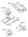
- FIG. 1 this schematically shows an attachment in the form of a visor 1 mounted on the rear screen 2 of a vehicle (not shown).
- the visor includes a single piece moulded structure formed conveniently from a plastics material and including an upper louvre 3, a bottom louvre 4 and intermediate louvres 5.
- the number of intermediate louvres can differ from the number shown in Figure 1.
- the end region of the louvres 3, 4 and 5 comprise transverse end walls 3A, 4A, and 5A which connect with a side edge strip 6.
- the top edge of the louvre 3 terminates as an upper edge strip 7 which lies in the same plane as the edge strips 6.
- the louvres are profiled for both structural strength and visual appearance. For convenience of description herein they can be regarded as forming a series of spaced parallel strips which do not overlap.
- the relationship of the upper edge 8 of any louvre with the rear edge 9 of the next adjacent louvre is to produce a narrow slot 10 which extends for substantially the full width of the panel or visor. In the Figure there are three such slots respectively provided between the louvre pairs 3-5, 5-5, 5-4.
- a fourth slot 11 is effectively produced between the rear part of the bottom louvre 4 and the adjacent surface of the screen 2.
- the adjacent louvre pairs are structurally reinforced at their mid points by interconnecting profiled ribs 12 which essentially provide risers between adjacent louvres.
- the bottom louvre 4 is provided with a profiled strengthening and air flow deflector or spoiler section 13 including a wall forming piece 14 lying generally transverse to the plane of the main body of the louvre 4.
- An attachment lug 15 shaped to provide a substantially rigid structure is provided at the midpoint of the wall piece 14.
- An aperture 16 is provided in the lug.
- top edge 7 is stopped as at 17, whilst the body of the louvre 3 is provided with an integral raised portion 18 having a wall 19 running transverse to the surface of the louvre. This wall is apertured as at 20.
- Each end region of the bottom louvre is shaped to provide a mounting lug 21 for a part of the attachment system of the invention.
- the lug is shaped so as to provide two support pads 22 which lie in the general plane of the two side edge strips 6 and intended to bear against the screen when the visor is fitted.
- the portion of the lug 21 lying between the pads 22 is stepped or otherwise raised above the plane of the pads 22.
- This lug formation is shown in greater detail in Figure 2.
- the central portion 23 of the lug 21 is apertured as at 24 to receive a locking element 25 having a cylindrical section 26 which is freely rotatable in the aperture 24.
- the element 25 is held in place by annular flanges 27 and 28 integral with the section 26, the flange 27 being dimensioned and shaped as to be able to enter the aperture 24 and to be pushed therethrough to the position shown but cannot subsequently be removed.
- the element 25 is provided with a finger grip 29 with a slot 30 for receiving a coin, screwdriver or the like aid to rotation.
- a short cylindrical neck 31 extends in prolongation of the section 26.
- a cross piece 32 is provided at the end of the neck 31. The neck and cross piece combine to provide a locking element with respect to a suitably shaped 'keyhole' 33 provided in a boss 34 upstanding from a generally rectangular element 35. As can be more readily seen from Figure 3 the cross piece 32 will enter the 'keyhole' when aligned as indicated in Figure 3 but is not able to engage or dis-engage from the 'keyhole' when in other positions.
- the rectangular element 35 is formed from a plastics material and is of such thickness that the part 36 can be inserted between the moulding 2A holding the screen in place and the surface of the screen.
- the edge 37 of the part 36 is provided with short lugs 38 which are intended to hook over the edge of the screen when the part 36 is inserted as described.
- the top edge 7 and the side edges 6 of the visor 1 are retained in place by retaining elements 39 such as is illustrated in Figure 4.
- the element 39 includes a first flat elongate part 40 which is intended to be inserted between the screen and the rubber moulding 2A which is for this reason provided with short lugs 41 which are able to hook over the edge of the screen, a small part of which is shown at 42 in Figure 4.
- the element 39 includes a second flat elongate part 43 which is spaced from the surface of the screen by means of a step so that when the part 40 is inserted between the screen 42 and the moulding 2A a slot 45 is produced into which the relevant edge 6, 7 of the visor can be inserted. It will be understood that the resiliency of the moulding in conjunction with the relative dimensions of the element 39 ensures a firm grip.
- the element of Figure 4 can be of rectangular shape or curved according to whether or not the element is required to co-operate with a corner area or a straight section of the edge of the panel.
- additional retaining elements are provided for positionally locating a bar or rod 51 which is attachable to the visor.
- Each support 46 includes a rectangular base 47 of which a part 48 is intended to be inserted between the screen 2 and the rubber surround 2A. This part of the base 47 is provided with the shallow lugs (not shown) for hooking over the edge of the screen.
- An upstanding block or pillar 49 is provided on the base 47. The pillar has a bore 50 into which the end of the rod 51 is to be inserted as a firm push fit.
- An outwardly directed spigot 52 extends from the pillar.
- Two of the supports 46 are provided in such positions that the spigots 52 can engage in the apertures 16 and 20.
- the rod 51 in extending along the central region of the louvres 3, 4, 5 and thus the visor provides a stiffening and support for the central part of the visor. For this reason the profiling and shaping of the risers or ribs 12, and if necessary the louvres are grooved or otherwise channelled to accommodate the bar 51.
- the above described attachment elements are used to secure the visor to the screen surround and the attachment of the visor can be as follows, the rod 51 is engaged in the two supports, 46, so that the spigots 52 face away from each other with the parts 48 engaged in the nip of the resilient screen border 2A and the screen.
- the stepped elements 39 can then be fitted or alternatively they can be left to a later stage.
- the parts 36 of the elements 35 are fitted and the locking elements 25 are engaged with the keyhole slots 33 in the parts 35.
- the stepped parts 39 can now be fitted if they have not already been fitted.
- this shows a modification of the element 25 in which the finger grip is dispensed with and the slot 30 is formed directly in the surface of the annular flange 28.
- the surface of the annular flange is adapted for receiving an Allen type key. If desired the element surface could be provided with a boss with flats for receiving a spanner.
Landscapes
- Engineering & Computer Science (AREA)
- Mechanical Engineering (AREA)
- General Engineering & Computer Science (AREA)
- Insertion Pins And Rivets (AREA)
- Connection Of Plates (AREA)
- Snaps, Bayonet Connections, Set Pins, And Snap Rings (AREA)
- Vehicle Step Arrangements And Article Storage (AREA)
- Supports Or Holders For Household Use (AREA)
Claims (3)
Priority Applications (1)
| Application Number | Priority Date | Filing Date | Title |
|---|---|---|---|
| AT79301088T ATE594T1 (de) | 1978-06-10 | 1979-06-08 | Befestigung grossflaechiger artikel durch ein mit den scharfen kanten der artikel kooperierendes befestigungssystem. |
Applications Claiming Priority (2)
| Application Number | Priority Date | Filing Date | Title |
|---|---|---|---|
| GB7826661 | 1978-06-10 | ||
| GB2666178 | 1978-06-10 |
Publications (3)
| Publication Number | Publication Date |
|---|---|
| EP0006332A1 EP0006332A1 (de) | 1980-01-09 |
| EP0006332B1 EP0006332B1 (de) | 1982-01-20 |
| EP0006332B2 true EP0006332B2 (de) | 1984-12-12 |
Family
ID=10497922
Family Applications (1)
| Application Number | Title | Priority Date | Filing Date |
|---|---|---|---|
| EP79301088A Expired EP0006332B2 (de) | 1978-06-10 | 1979-06-08 | Befestigung grossflächiger Artikel durch ein mit den scharfen Kanten der Artikel kooperierendes Befestigungssystem |
Country Status (3)
| Country | Link |
|---|---|
| EP (1) | EP0006332B2 (de) |
| AT (1) | ATE594T1 (de) |
| ES (1) | ES243829Y (de) |
Families Citing this family (1)
| Publication number | Priority date | Publication date | Assignee | Title |
|---|---|---|---|---|
| AU574329B2 (en) * | 1982-08-10 | 1988-07-07 | Aunger, Kim Garfield | Affixing rear louvre to car |
Family Cites Families (4)
| Publication number | Priority date | Publication date | Assignee | Title |
|---|---|---|---|---|
| US1785709A (en) * | 1930-04-14 | 1930-12-16 | Harry Bonifacio | Bolt and bushing therefor |
| US2884677A (en) * | 1953-07-02 | 1959-05-05 | Victor F Zahodiakin | Fastening device |
| DE7535625U (de) * | 1975-11-08 | 1976-11-11 | Dietzsch, Werner, Ing.(Grad.), 2900 Oldenburg | Jalousieartige aussenabdeckung fuer kraftfahrzeugfenster |
| DE7717965U1 (de) * | 1977-06-06 | 1977-10-06 | Ulbrich, Hubertus, 3180 Wolfsburg | Autojalousie |
-
1979
- 1979-06-08 EP EP79301088A patent/EP0006332B2/de not_active Expired
- 1979-06-08 AT AT79301088T patent/ATE594T1/de not_active IP Right Cessation
- 1979-06-08 ES ES1979243829U patent/ES243829Y/es not_active Expired
Also Published As
| Publication number | Publication date |
|---|---|
| ES243829Y (es) | 1980-10-01 |
| ATE594T1 (de) | 1982-02-15 |
| EP0006332A1 (de) | 1980-01-09 |
| EP0006332B1 (de) | 1982-01-20 |
| ES243829U (es) | 1980-01-16 |
Similar Documents
| Publication | Publication Date | Title |
|---|---|---|
| US4731960A (en) | Molding strip assembly with reveal and shelving system for use in constructing flexible wall coverings | |
| US5516183A (en) | Automotive window assembly system | |
| US3778958A (en) | Panel spacing and holding clip | |
| US4205875A (en) | Roof vent window | |
| US5137072A (en) | Sun curtain assembly for industrial vehicle and building windows | |
| CA2317220A1 (en) | Reinforcement system for an automotive vehicle fender and bracket therefor | |
| US5188408A (en) | Mechanical lock for vehicle trim panels and the like | |
| JPH11230135A (ja) | 物品取付具 | |
| US4888929A (en) | Self-locking door trim for flush glass | |
| EP0006332B2 (de) | Befestigung grossflächiger Artikel durch ein mit den scharfen Kanten der Artikel kooperierendes Befestigungssystem | |
| US6938929B2 (en) | Vehicle mud flap | |
| US5033246A (en) | Self-locking door trim for flush glass | |
| US20040094937A1 (en) | Deflectable airbag housing mounting tabs | |
| JP7765819B2 (ja) | 引手 | |
| JP3465290B2 (ja) | フェンダパネルの取付構造 | |
| US20050225071A1 (en) | Vehicle mud flap | |
| CN217685804U (zh) | 一种面板装饰条装配结构 | |
| JP2593911Y2 (ja) | モール取付構造 | |
| CN216734133U (zh) | 一种车门门框饰板结构 | |
| JPH06171366A (ja) | 自動車のドア | |
| JP2519754Y2 (ja) | 自動車のフロントグリル取付構造 | |
| JPS6214405Y2 (de) | ||
| JPH0641884Y2 (ja) | トランクルームトリムの取付構造 | |
| JPH0223718Y2 (de) | ||
| JP2000240361A (ja) | 窓枠の構造 |
Legal Events
| Date | Code | Title | Description |
|---|---|---|---|
| PUAI | Public reference made under article 153(3) epc to a published international application that has entered the european phase |
Free format text: ORIGINAL CODE: 0009012 |
|
| AK | Designated contracting states |
Designated state(s): AT BE CH FR GB IT LU NL SE |
|
| 17P | Request for examination filed | ||
| ITF | It: translation for a ep patent filed | ||
| GRAA | (expected) grant |
Free format text: ORIGINAL CODE: 0009210 |
|
| AK | Designated contracting states |
Designated state(s): AT BE CH FR GB IT LU NL SE |
|
| REF | Corresponds to: |
Ref document number: 594 Country of ref document: AT Date of ref document: 19820215 Kind code of ref document: T |
|
| PG25 | Lapsed in a contracting state [announced via postgrant information from national office to epo] |
Ref country code: LU Free format text: LAPSE BECAUSE OF NON-PAYMENT OF DUE FEES Effective date: 19820630 |
|
| PLBI | Opposition filed |
Free format text: ORIGINAL CODE: 0009260 |
|
| 26 | Opposition filed |
Opponent name: THERMOFORM A/S Effective date: 19821019 |
|
| PGFP | Annual fee paid to national office [announced via postgrant information from national office to epo] |
Ref country code: LU Payment date: 19830527 Year of fee payment: 5 |
|
| PGFP | Annual fee paid to national office [announced via postgrant information from national office to epo] |
Ref country code: FR Payment date: 19840522 Year of fee payment: 6 |
|
| PGFP | Annual fee paid to national office [announced via postgrant information from national office to epo] |
Ref country code: CH Payment date: 19840625 Year of fee payment: 6 |
|
| PGFP | Annual fee paid to national office [announced via postgrant information from national office to epo] |
Ref country code: AT Payment date: 19840627 Year of fee payment: 6 |
|
| PGFP | Annual fee paid to national office [announced via postgrant information from national office to epo] |
Ref country code: SE Payment date: 19840630 Year of fee payment: 6 Ref country code: BE Payment date: 19840630 Year of fee payment: 6 |
|
| ITF | It: translation for a ep patent filed | ||
| PUAH | Patent maintained in amended form |
Free format text: ORIGINAL CODE: 0009272 |
|
| STAA | Information on the status of an ep patent application or granted ep patent |
Free format text: STATUS: PATENT MAINTAINED AS AMENDED |
|
| 27A | Patent maintained in amended form | ||
| AK | Designated contracting states |
Kind code of ref document: B2 Designated state(s): AT BE CH FR GB IT LU NL SE |
|
| NLR3 | Nl: receipt of modified translations in the netherlands language after an opposition procedure | ||
| PG25 | Lapsed in a contracting state [announced via postgrant information from national office to epo] |
Ref country code: AT Effective date: 19850608 |
|
| PGFP | Annual fee paid to national office [announced via postgrant information from national office to epo] |
Ref country code: NL Payment date: 19850630 Year of fee payment: 7 |
|
| PG25 | Lapsed in a contracting state [announced via postgrant information from national office to epo] |
Ref country code: CH Effective date: 19860630 Ref country code: BE Effective date: 19860630 |
|
| BERE | Be: lapsed |
Owner name: HARRIS KENNETH ALBERT Effective date: 19860630 |
|
| PG25 | Lapsed in a contracting state [announced via postgrant information from national office to epo] |
Ref country code: NL Effective date: 19870101 |
|
| NLV4 | Nl: lapsed or anulled due to non-payment of the annual fee | ||
| PG25 | Lapsed in a contracting state [announced via postgrant information from national office to epo] |
Ref country code: FR Free format text: LAPSE BECAUSE OF NON-PAYMENT OF DUE FEES Effective date: 19870227 |
|
| REG | Reference to a national code |
Ref country code: CH Ref legal event code: PL |
|
| GBPC | Gb: european patent ceased through non-payment of renewal fee | ||
| REG | Reference to a national code |
Ref country code: FR Ref legal event code: ST |
|
| PG25 | Lapsed in a contracting state [announced via postgrant information from national office to epo] |
Ref country code: SE Effective date: 19870609 |
|
| PG25 | Lapsed in a contracting state [announced via postgrant information from national office to epo] |
Ref country code: GB Effective date: 19881118 |
|
| EUG | Se: european patent has lapsed |
Ref document number: 79301088.5 Effective date: 19880711 |