EP0006367A1 - Auslösungseinrichtung, insbesondere für die Zündung einer Brennkraftmaschine - Google Patents
Auslösungseinrichtung, insbesondere für die Zündung einer Brennkraftmaschine Download PDFInfo
- Publication number
- EP0006367A1 EP0006367A1 EP79400292A EP79400292A EP0006367A1 EP 0006367 A1 EP0006367 A1 EP 0006367A1 EP 79400292 A EP79400292 A EP 79400292A EP 79400292 A EP79400292 A EP 79400292A EP 0006367 A1 EP0006367 A1 EP 0006367A1
- Authority
- EP
- European Patent Office
- Prior art keywords
- counter
- divider
- output
- sensors
- programmable
- Prior art date
- Legal status (The legal status is an assumption and is not a legal conclusion. Google has not performed a legal analysis and makes no representation as to the accuracy of the status listed.)
- Granted
Links
- 238000002485 combustion reaction Methods 0.000 title claims description 6
- 238000012937 correction Methods 0.000 claims description 9
- 230000006870 function Effects 0.000 claims description 9
- 239000000654 additive Substances 0.000 claims description 2
- 230000000996 additive effect Effects 0.000 claims description 2
- 238000010586 diagram Methods 0.000 description 5
- 235000021183 entrée Nutrition 0.000 description 3
- 238000005516 engineering process Methods 0.000 description 2
- 238000004519 manufacturing process Methods 0.000 description 2
- 238000005259 measurement Methods 0.000 description 2
- 238000007493 shaping process Methods 0.000 description 2
- 241001080024 Telles Species 0.000 description 1
- 230000001419 dependent effect Effects 0.000 description 1
- 230000004048 modification Effects 0.000 description 1
- 238000012986 modification Methods 0.000 description 1
- 239000004065 semiconductor Substances 0.000 description 1
- 230000001629 suppression Effects 0.000 description 1
- 230000001960 triggered effect Effects 0.000 description 1
Images


Classifications
-
- F—MECHANICAL ENGINEERING; LIGHTING; HEATING; WEAPONS; BLASTING
- F02—COMBUSTION ENGINES; HOT-GAS OR COMBUSTION-PRODUCT ENGINE PLANTS
- F02P—IGNITION, OTHER THAN COMPRESSION IGNITION, FOR INTERNAL-COMBUSTION ENGINES; TESTING OF IGNITION TIMING IN COMPRESSION-IGNITION ENGINES
- F02P7/00—Arrangements of distributors, circuit-makers or -breakers, e.g. of distributor and circuit-breaker combinations or pick-up devices
- F02P7/06—Arrangements of distributors, circuit-makers or -breakers, e.g. of distributor and circuit-breaker combinations or pick-up devices of circuit-makers or -breakers, or pick-up devices adapted to sense particular points of the timing cycle
- F02P7/077—Circuits therefor, e.g. pulse generators
- F02P7/0775—Electronical verniers
-
- F—MECHANICAL ENGINEERING; LIGHTING; HEATING; WEAPONS; BLASTING
- F02—COMBUSTION ENGINES; HOT-GAS OR COMBUSTION-PRODUCT ENGINE PLANTS
- F02P—IGNITION, OTHER THAN COMPRESSION IGNITION, FOR INTERNAL-COMBUSTION ENGINES; TESTING OF IGNITION TIMING IN COMPRESSION-IGNITION ENGINES
- F02P5/00—Advancing or retarding ignition; Control therefor
- F02P5/04—Advancing or retarding ignition; Control therefor automatically, as a function of the working conditions of the engine or vehicle or of the atmospheric conditions
- F02P5/145—Advancing or retarding ignition; Control therefor automatically, as a function of the working conditions of the engine or vehicle or of the atmospheric conditions using electrical means
- F02P5/15—Digital data processing
-
- Y—GENERAL TAGGING OF NEW TECHNOLOGICAL DEVELOPMENTS; GENERAL TAGGING OF CROSS-SECTIONAL TECHNOLOGIES SPANNING OVER SEVERAL SECTIONS OF THE IPC; TECHNICAL SUBJECTS COVERED BY FORMER USPC CROSS-REFERENCE ART COLLECTIONS [XRACs] AND DIGESTS
- Y02—TECHNOLOGIES OR APPLICATIONS FOR MITIGATION OR ADAPTATION AGAINST CLIMATE CHANGE
- Y02T—CLIMATE CHANGE MITIGATION TECHNOLOGIES RELATED TO TRANSPORTATION
- Y02T10/00—Road transport of goods or passengers
- Y02T10/10—Internal combustion engine [ICE] based vehicles
- Y02T10/40—Engine management systems
Definitions
- the present invention due to the collaboration of Mr. Jacques GOUX, relates to an electronic device for controlling the triggering of an operating operation on a rotating machine. It applies more particularly to the triggering of ignition on an internal combustion engine.
- this angle In order for the engine to always operate, under the best conditions, this angle must be constantly corrected according to various operating parameters of the engine, in particular its speed of rotation.
- All known electronic ignition devices therefore include, in particular, means for measuring the engine rotation speed and means for triggering the ignition as a function of the measured speed.
- These devices include one or two magnetic sensors placed in the vicinity of a disc provided, as the case may be, with one or more teeth or notches and rotating at the speed of the motor.
- the main object of the invention is to overcome this drawback.
- a device for triggering, in particular the ignition of an internal combustion engine comprising means for measuring the speed of rotation of the engine which comprise first and second sensors offset one with respect to the other of a predetermined angle and a movable mark in front of the sensors, mounted on a disc secured to the motor shaft, and means for triggering the ignition as a function of the measured rotation speed, characterized in that said means for measuring the speed of rotation further comprise a first programmable down-counter divider whose input is connected to a clock intended to supply it with signals at a frequency fo and whose output is connected to a counter intended to count the signals delivered by the programmable down-counter divider, the frequency fc of said signals being equal to the frequency fo of the clock signals divided by the value of the angle ⁇ equal to the difference between 360 ° and the angle ⁇ of offset between the first and the second sensor, said counter being in turn connected to an address input of a memory containing different values of ignition advance angles, the output of said memory being connected to a second programmable down-counter
- the device shown schematically in FIG. 1 comprises two sensors 1 and 2 intended to detect the passage of a mark 3 constituted for example by a notch formed at the periphery of the flywheel 4 of an internal combustion engine not shown.
- the sensor 2 and the mark 3 are positioned so that the passage of the mark in front of the sensor takes place for an angular position of the crankshaft corresponding to the minimum advance at ignition ai.
- the sensor 1 is positioned in advance of ⁇ degrees on the sensor 2, the value of the angle ⁇ being such that is greater than the maximum amplitude desired in advance relative to the initial advance.
- the sensors 1 and 2 are respectively connected to shaping amplifiers 5 and 6, the outputs of which are each connected to an input of a rocker circuit 7.
- a first output of the rocker 7 is connected to a switch 8 intended to connect a circuit 9 for memorizing the angle value ⁇ equal to the difference between 360 ° and the angle ⁇ separating the sensors 1 and 2, to a first programmable down-counter divider 10 whose input is connected to the output of a circuit the clock 11 and the output of which is connected to a switch 12, itself connected on the one hand to a counter 13 and on the other hand to a second programmable divider decoder 14
- the switch 12 is controlled by the second output of the rocker 7, as is a first contact 15 connecting the output of the counter 13 to the input of a locking circuit 16.
- a second contact 17 also controlled by the second output of the rocker 7, is connected between the second programmable down-counter divider 14 and the output of a memory 18 the input of which is connected to the output of the locking circuit 16, the latter also being connected to the first programmable down-counter divider 10 by via the switch 8. It goes without saying that the switches 8, 12 and the contacts 15, 17 can be controlled, either by one or the other of the outputs of the rocker 7.
- the output of the second programmable down-counter divider 14 is connected to the input of a power stage 19 supplying the ignition coil 20 of a spark plug 21.
- the circuit which has just been described is added a part shown in phantom and comprising a pressure sensor 22 and an analog-digital converter 23 connected to additional address inputs of the memory 18.
- the device represented in FIG. 2 behaves like that of FIG. 1, two sensors 24 and 25 placed in the vicinity of a disc 26 provided with a notch 27.
- the positioning of the sensors 24 and 25 is similar to that of the sensors 1 and 2 of the device shown in FIG. 1.
- the outputs of sensors 24 and 25 are connected via shaping circuits 26 and 27, to the inputs of a rocker circuit 28, a first output of which controls a switch 29.
- the latter is intended to connect a programmable divider decoder 30 receiving pulses from a clock 31, either to a circuit 32 for memorizing the angle B equal to the difference between 360 ° and the angle separating the two sensors 24 and 25, or to a locking circuit 33.
- the other output of the rocker 28 controls a second switch 34 intended to connect the programmable down-counter divider 30 to a first or a second input of a prepositionable up-down counter 35 whose output is connected to a power stage 36 of supply of the ignition coil 37 of the spark plugs such as 38 of an engine not shown.
- the up-down counter 35 has an output connected to the locking circuit 33 via a contact 39 coupled to the switch 34.
- the output of the locking circuit 33 is connected to a memory 40 and to the programmable down-counting divider 30 by the intermediate of the switch 29.
- the output of the memory 40 is in turn connected to a binary adder 41, another input of which is connected, by means of a circuit 42 of additive corrections, to sensors 43 such as pressure, temperature, etc.
- the output of the binary adder is connected to a prepositioning input of the up-down counter 35, via another contact 44 coupled to the switch 34.
- the switches 29, 34 and the contacts 39, 44 can be controlled indifferently, by one or the other of the outputs of the rocker 7.
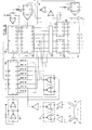
- the device of FIG. 5 comprises other circuits which are not shown in FIG. 1. These are, for example, adders 45 and 46 interposed between the memory 18 and the programmable down-counter divider 14. In the embodiment, these two adders are 4-bit adders of the CD 4008 type.
- the rocker circuit 7 is a CD 4001 type circuit, while the clock 11 is formed by half of a 4001 type circuit. When in memory 18 it is of current type and of indifferent technology, its capacity generally being 256 words of 8 bits.
- the output signals from sensors 1 and 2 are shaped by stages 5 and 6 and each control an input of the flip-flop 7, the state of which depends on the position of the mark 3 relative to sensors 1 and 2.
- the flip-flop 7 controls the counting in the counter 13, of pulses which are supplied to it at the frequency fc and which are obtained from the clock 11 which delivers pulses of frequency fo, these pulses passing through the programmable down-counter divider 10, programmed by the flip-flop 7 to divide the frequency of these pulses by the value of the angle f3 stored in the circuit 9, during the counting phase.
- fc fo / ⁇ .
- n fc xt, t being the time necessary for the frame 3 to traverse the angle ⁇ .
- each pulse delivered at the frequency fd corresponds to a rotation of 1 degree, so that the programmable down-counter divider 14 reaches zero when the mark 3 has traveled aw degrees after passing in front of sensor 1.
- the programmable down-counter divider 14 generates a signal when it reaches the value zero. This signal, via the power stage 19 and the coil 20 causes the appearance of a spark on the spark plug 21.
- This ignition spark occurs for a position of the mark 3 located between the sensors 1 and 2, inside the angle ⁇ .
- the rocker 7 returns to its initial position and triggers a new counting cycle.
- the device which has just been described has the following particularities.
- a programmable down-counter divider 10 For the measurement of the angular velocities, between the clock 11 delivering the frequency fo and the counter 13 which totals up to the number n, a programmable down-counter divider 10, the division factor of which is chosen equal to the value of the angle ⁇ expressed in degrees, during which this measurement is made.
- the same clock 11 and the same programmable downcounter circuit 10 are used, but the division factor of which is chosen to be equal at the velocity n measured during the previous counting phase, which makes it possible to have, at the output of the programmable down-counter divider 10, a down-count frequency f d such that each pulse corresponds to a degree of rotation of the engine flywheel, whatever the angular speed and the position of the sensors on it. This makes it possible to store directly in the memory 18 advance values expressed in degrees.
- the counting and down counting phases being successive and without overlap, it is easy to replace the counter 13 and the down counter 14 by a single up-down counter circuit in order to simplify the production. Such a replacement is ensured in the device shown diagrammatically in FIG. 2.
Landscapes
- Engineering & Computer Science (AREA)
- Chemical & Material Sciences (AREA)
- Combustion & Propulsion (AREA)
- Mechanical Engineering (AREA)
- General Engineering & Computer Science (AREA)
- Signal Processing (AREA)
- Electrical Control Of Ignition Timing (AREA)
- Ignition Installations For Internal Combustion Engines (AREA)
- Combined Controls Of Internal Combustion Engines (AREA)
Applications Claiming Priority (2)
| Application Number | Priority Date | Filing Date | Title |
|---|---|---|---|
| FR7817157 | 1978-06-08 | ||
| FR7817157A FR2428151A1 (fr) | 1978-06-08 | 1978-06-08 | Dispositif de declenchement, notamment de l'allumage d'un moteur a combustion interne |
Publications (2)
| Publication Number | Publication Date |
|---|---|
| EP0006367A1 true EP0006367A1 (de) | 1980-01-09 |
| EP0006367B1 EP0006367B1 (de) | 1981-05-20 |
Family
ID=9209242
Family Applications (1)
| Application Number | Title | Priority Date | Filing Date |
|---|---|---|---|
| EP79400292A Expired EP0006367B1 (de) | 1978-06-08 | 1979-05-08 | Auslösungseinrichtung, insbesondere für die Zündung einer Brennkraftmaschine |
Country Status (5)
| Country | Link |
|---|---|
| US (1) | US4296471A (de) |
| EP (1) | EP0006367B1 (de) |
| JP (1) | JPS551491A (de) |
| DE (1) | DE2960368D1 (de) |
| FR (1) | FR2428151A1 (de) |
Cited By (1)
| Publication number | Priority date | Publication date | Assignee | Title |
|---|---|---|---|---|
| EP0105417A3 (de) * | 1982-10-01 | 1985-07-03 | Rockwell International Corporation | Verfahren und Gerät zur Bestimmung der besonderen Lage eines Kolbens |
Families Citing this family (20)
| Publication number | Priority date | Publication date | Assignee | Title |
|---|---|---|---|---|
| DE3107937C2 (de) * | 1980-03-03 | 1987-03-19 | Mitsubishi Denki K.K., Tokio/Tokyo | Zündzeit-Steuereinrichtung für eine Brennkraftmaschine |
| US4385227A (en) * | 1980-03-06 | 1983-05-24 | Bridges Danny E | Automatic delay and high velocity sensing system |
| US4408296A (en) * | 1980-08-27 | 1983-10-04 | Rca Corporation | Digital timing system for spark advance |
| US4638498A (en) * | 1980-06-20 | 1987-01-20 | Rca Corporation | Digital timing system |
| FR2485641A1 (fr) * | 1980-06-26 | 1981-12-31 | Renault | Procede et dispositif de commande electronique d'allumage pour moteur a combustion interne |
| GB2097540B (en) * | 1981-04-13 | 1984-11-28 | Tokyo Shibaura Electric Co | Integrating meter with rotor and magnetoresistive sensor |
| JPS59139754U (ja) * | 1983-03-04 | 1984-09-18 | 株式会社トヨトミ | バ−ナの安全装置 |
| DE3407790A1 (de) * | 1983-06-23 | 1985-01-03 | VEB Kombinat Polygraph "Werner Lamberz" Leipzig, DDR 7050 Leipzig | Takterzeugungseinrichtung fuer druckmaschinen |
| DE3406969A1 (de) * | 1983-06-23 | 1985-01-10 | VEB Kombinat Polygraph "Werner Lamberz" Leipzig, DDR 7050 Leipzig | Takterzeugungseinrichtung fuer druckmaschinen |
| DD228700A3 (de) * | 1983-06-23 | 1985-10-16 | Falk Buschmann | Takterzeugungseinrichtung fuer druckmaschinen |
| JPH0692781B2 (ja) * | 1984-03-07 | 1994-11-16 | 国産電機株式会社 | 内燃機関点火装置 |
| JPH0658223B2 (ja) * | 1985-06-13 | 1994-08-03 | 株式会社ゼクセル | 回転装置用タイミング信号発生装置 |
| DE3602292A1 (de) * | 1986-01-25 | 1987-08-06 | Audi Ag | Geberanordnung |
| JPS63238329A (ja) * | 1987-03-24 | 1988-10-04 | Rinnai Corp | 燃焼検知装置 |
| US5043659A (en) * | 1989-12-18 | 1991-08-27 | Clean Air Technologies Inc. | Non-intrusive tachometer for spark ignition autos |
| CA2104144C (en) * | 1992-08-21 | 2004-01-06 | Jay C. Mccombie | Dual sensor misfire detection apparatus and method for an internal combustion engine |
| US5297048A (en) * | 1992-09-21 | 1994-03-22 | Automotive Integrated Electronics Co., Inc. | Angular position extrapolation of a rotating crankshaft corrected for crankshaft acceleration and deceleration |
| US5610327A (en) * | 1995-06-07 | 1997-03-11 | Snap-On Technologies, Inc. | Knock sensor-triggered timing light with visible laser retro-reflecting control |
| US5883510A (en) * | 1997-05-13 | 1999-03-16 | Spx Corporation | Tachometer system picking up ignition signals from vehicle ground |
| US6192861B1 (en) * | 1997-12-11 | 2001-02-27 | Aisan Kogyo Kabushiki Kaisha | Engine ignition device |
Citations (4)
| Publication number | Priority date | Publication date | Assignee | Title |
|---|---|---|---|---|
| FR2248511A1 (de) * | 1973-10-17 | 1975-05-16 | Sopromi Soc Proc Modern Inject | |
| US4009378A (en) * | 1973-12-07 | 1977-02-22 | Hitachi, Ltd. | Ignition timing control system for an internal combustion engine |
| FR2331204A1 (fr) * | 1975-11-07 | 1977-06-03 | Texas Instruments France | Dispositif de multiplication de frequence et ses applications au codage angulaire d'un organe rotatif et a l'allumage electronique d'un moteur |
| DE2703575A1 (de) * | 1976-01-28 | 1977-08-11 | Hitachi Ltd | Einrichtung zum steuern des zuendzeitpunkts einer brennkraftmaschine |
Family Cites Families (11)
| Publication number | Priority date | Publication date | Assignee | Title |
|---|---|---|---|---|
| US3738339A (en) * | 1971-12-06 | 1973-06-12 | Gen Motors Corp | Electronic ignition spark advance system |
| US3767902A (en) * | 1972-12-12 | 1973-10-23 | Essex International Inc | Engine member position predictor |
| US3870869A (en) * | 1973-04-26 | 1975-03-11 | Columbia Gas Syst | Digital apparatus for the timing and analysis of internal combustion engines |
| CH565946A5 (de) * | 1973-07-23 | 1975-08-29 | Hartig Gunter | |
| US3996911A (en) * | 1974-12-19 | 1976-12-14 | Texaco Inc. | Means and method for controlling the occurrence and the duration of time intervals during which sparks are provided in a multicylinder internal combustion engine |
| DE2623613C2 (de) * | 1976-05-26 | 1982-12-23 | Robert Bosch Gmbh, 7000 Stuttgart | Zündanlage mit einer Zündwinkelverstellvorrichtung |
| US4086894A (en) * | 1976-07-06 | 1978-05-02 | Motorola, Inc. | Rotary direction sensor for engine ignition control |
| US4125097A (en) * | 1976-12-03 | 1978-11-14 | Motorola, Inc. | Electronic ignition timing advance circuit |
| DE2702208A1 (de) * | 1977-01-20 | 1978-07-27 | Bosch Gmbh Robert | Verfahren und einrichtung zur ausloesung eines impulses innerhalb eines verstellbereiches |
| US4168682A (en) * | 1977-03-22 | 1979-09-25 | Motorola, Inc. | Electronic ignition timing system using digital rate multiplication |
| US4181962A (en) * | 1978-02-27 | 1980-01-01 | The United States Of America As Represented By The Secretary Of The Navy | Digital programmable timing device |
-
1978
- 1978-06-08 FR FR7817157A patent/FR2428151A1/fr active Granted
-
1979
- 1979-05-08 DE DE7979400292T patent/DE2960368D1/de not_active Expired
- 1979-05-08 EP EP79400292A patent/EP0006367B1/de not_active Expired
- 1979-06-05 US US06/045,770 patent/US4296471A/en not_active Expired - Lifetime
- 1979-06-08 JP JP7213079A patent/JPS551491A/ja active Pending
Patent Citations (4)
| Publication number | Priority date | Publication date | Assignee | Title |
|---|---|---|---|---|
| FR2248511A1 (de) * | 1973-10-17 | 1975-05-16 | Sopromi Soc Proc Modern Inject | |
| US4009378A (en) * | 1973-12-07 | 1977-02-22 | Hitachi, Ltd. | Ignition timing control system for an internal combustion engine |
| FR2331204A1 (fr) * | 1975-11-07 | 1977-06-03 | Texas Instruments France | Dispositif de multiplication de frequence et ses applications au codage angulaire d'un organe rotatif et a l'allumage electronique d'un moteur |
| DE2703575A1 (de) * | 1976-01-28 | 1977-08-11 | Hitachi Ltd | Einrichtung zum steuern des zuendzeitpunkts einer brennkraftmaschine |
Cited By (1)
| Publication number | Priority date | Publication date | Assignee | Title |
|---|---|---|---|---|
| EP0105417A3 (de) * | 1982-10-01 | 1985-07-03 | Rockwell International Corporation | Verfahren und Gerät zur Bestimmung der besonderen Lage eines Kolbens |
Also Published As
| Publication number | Publication date |
|---|---|
| JPS551491A (en) | 1980-01-08 |
| FR2428151B1 (de) | 1982-07-02 |
| US4296471A (en) | 1981-10-20 |
| EP0006367B1 (de) | 1981-05-20 |
| DE2960368D1 (en) | 1981-08-27 |
| FR2428151A1 (fr) | 1980-01-04 |
Similar Documents
| Publication | Publication Date | Title |
|---|---|---|
| EP0006367B1 (de) | Auslösungseinrichtung, insbesondere für die Zündung einer Brennkraftmaschine | |
| EP0333572B1 (de) | Vorrichtung zum Formatieren und Auswerten der von einem Gleichstrommotor generierten Induktionsströme, insbesondere zur Positionsregelung | |
| FR2484887A1 (fr) | Appareil de positionnement repere permettant de faire tourner a ses reperes une table rotative | |
| FR2524557A1 (fr) | Dispositif de controle de cognement pour un moteur a combustion interne | |
| EP0013846B1 (de) | Verfahren und Vorrichtung zur Bestimmung der Winkellage eines rotierenden Teiles | |
| CH625596A5 (de) | ||
| FR2463935A1 (fr) | Dispositif pour la detection de la vitesse de rotation et la detection d'un angle de rotation d'un arbre, en particulier du vilebrequin d'un moteur a combustion interne | |
| CH630442A5 (fr) | Procede et dispositif de reglage automatique de l'allumage d'un moteur a allumage commande. | |
| FR2459377A1 (fr) | Dispositif de reglage de l'allumage pour un moteur a combustion interne et dispositif pour y detecter un cliquetis s'y produisant | |
| FR3033051A1 (fr) | Procede et dispositif de traitement d'un signal produit par un capteur de rotation d'une cible tournante | |
| EP0010033A1 (de) | Winkelgeber für Brennkraftmaschine mit einer elektronischen Zündanlage | |
| EP0032333B1 (de) | Vorrichtung zur Erkennung von Verbrennungsstörungen in einem Explosionsmotor | |
| WO1979000808A1 (fr) | Dispositif de mesure de la frequence d'un generateur d'impulsions et systeme de commande numerique comportant un tel dispositif | |
| FR2527802A1 (fr) | Convertisseur incrementiel-numerique | |
| CH645161A5 (fr) | Procede et dispositif de commande automatique d'un circuit d'allumage d'un moteur a combustion interne. | |
| FR2583166A1 (fr) | Dispositif de mesure de la vitesse de deplacement d'un vehicule | |
| FR2591751A1 (fr) | Dispositif d'elaboration d'un signal de tachymetrie de resolution infinie et sans ondulation a partir d'un capteur de position inductif | |
| EP0009443B1 (de) | Digitales Vergleichsgerät der Winkelgeschwindigkeit und mit einer solchen Vorrichtung versehene Motorsteuerung | |
| EP0029374A1 (de) | Signal-generator zur Korrektur der Einstellung der Frühzündung in Abhängigkeit vom Klopfverhalten | |
| FR2566839A1 (fr) | Capteur destine a detecter le passage d'un piston ou groupe de pistons d'un moteur a combustion interne par la position du point mort haut | |
| FR2901928A1 (fr) | Procede et dispositif de generation de signaux de commande d'une machine electrique tournante polyphasee en fonction de la vitesse | |
| EP0150642A2 (de) | Messeinrichtung für die Winkellage eines rotierenden Zahnrades | |
| FR2498255A1 (fr) | Dispositif d'ajustement rapide, en periode d'acceleration, de l'avance a l'allumage d'un moteur a allumage commande | |
| EP0272965A1 (de) | Frequenz-Spannungswandler | |
| EP0187071B1 (de) | Elektronische Schaltungsanordnung zur Verarbeitung eines Synchronsignals aus dem Zündzeitpunktsignal einer Brennkraftmaschine |
Legal Events
| Date | Code | Title | Description |
|---|---|---|---|
| PUAI | Public reference made under article 153(3) epc to a published international application that has entered the european phase |
Free format text: ORIGINAL CODE: 0009012 |
|
| AK | Designated contracting states |
Designated state(s): DE GB IT |
|
| 17P | Request for examination filed | ||
| ITF | It: translation for a ep patent filed | ||
| GRAA | (expected) grant |
Free format text: ORIGINAL CODE: 0009210 |
|
| AK | Designated contracting states |
Designated state(s): DE GB IT |
|
| REF | Corresponds to: |
Ref document number: 2960368 Country of ref document: DE Date of ref document: 19810827 |
|
| REG | Reference to a national code |
Ref country code: GB Ref legal event code: 746 |
|
| PGFP | Annual fee paid to national office [announced via postgrant information from national office to epo] |
Ref country code: DE Payment date: 19840411 Year of fee payment: 6 |
|
| ITPR | It: changes in ownership of a european patent |
Owner name: OFFERTA DI LICENZA AL PUBBLICO |
|
| PG25 | Lapsed in a contracting state [announced via postgrant information from national office to epo] |
Ref country code: GB Effective date: 19880508 |
|
| GBPC | Gb: european patent ceased through non-payment of renewal fee | ||
| PG25 | Lapsed in a contracting state [announced via postgrant information from national office to epo] |
Ref country code: DE Effective date: 19890201 |
|
| PLBE | No opposition filed within time limit |
Free format text: ORIGINAL CODE: 0009261 |
|
| STAA | Information on the status of an ep patent application or granted ep patent |
Free format text: STATUS: NO OPPOSITION FILED WITHIN TIME LIMIT |