EP0006476B1 - Appareil de reconnaissance de caractères utilisant un traitement de vecteurs de courbure - Google Patents
Appareil de reconnaissance de caractères utilisant un traitement de vecteurs de courbure Download PDFInfo
- Publication number
- EP0006476B1 EP0006476B1 EP79101709A EP79101709A EP0006476B1 EP 0006476 B1 EP0006476 B1 EP 0006476B1 EP 79101709 A EP79101709 A EP 79101709A EP 79101709 A EP79101709 A EP 79101709A EP 0006476 B1 EP0006476 B1 EP 0006476B1
- Authority
- EP
- European Patent Office
- Prior art keywords
- character
- canonic
- segment
- control
- characters
- Prior art date
- Legal status (The legal status is an assumption and is not a legal conclusion. Google has not performed a legal analysis and makes no representation as to the accuracy of the status listed.)
- Expired
Links
Images

Classifications
-
- G—PHYSICS
- G06—COMPUTING OR CALCULATING; COUNTING
- G06V—IMAGE OR VIDEO RECOGNITION OR UNDERSTANDING
- G06V10/00—Arrangements for image or video recognition or understanding
- G06V10/40—Extraction of image or video features
-
- G—PHYSICS
- G06—COMPUTING OR CALCULATING; COUNTING
- G06V—IMAGE OR VIDEO RECOGNITION OR UNDERSTANDING
- G06V10/00—Arrangements for image or video recognition or understanding
- G06V10/20—Image preprocessing
-
- G—PHYSICS
- G06—COMPUTING OR CALCULATING; COUNTING
- G06V—IMAGE OR VIDEO RECOGNITION OR UNDERSTANDING
- G06V30/00—Character recognition; Recognising digital ink; Document-oriented image-based pattern recognition
- G06V30/10—Character recognition
- G06V30/19—Recognition using electronic means
- G06V30/192—Recognition using electronic means using simultaneous comparisons or correlations of the image signals with a plurality of references
-
- G—PHYSICS
- G06—COMPUTING OR CALCULATING; COUNTING
- G06V—IMAGE OR VIDEO RECOGNITION OR UNDERSTANDING
- G06V30/00—Character recognition; Recognising digital ink; Document-oriented image-based pattern recognition
- G06V30/10—Character recognition
- G06V30/19—Recognition using electronic means
- G06V30/192—Recognition using electronic means using simultaneous comparisons or correlations of the image signals with a plurality of references
- G06V30/194—References adjustable by an adaptive method, e.g. learning
Definitions
- the present invention relates to the field of character recognition systems.
- the view system employs character recognition apparatus comprising means for establishing in binary storage an image of a character and means for analysing the stored character to produce feature signals dependant on features of the stored character.
- character recognition apparatus comprising means for establishing in binary storage an image of a character and means for analysing the stored character to produce feature signals dependant on features of the stored character.
- many hundreds of known characters are stored and analysed and the probability of any particular character having any particular feature is assessed.
- These probabilities are assembled into a notional matrix table having a row for each feature and a column for each character.
- the rows of the table are accessed in accordance with the analysed features of the unknown character and the character value corresponding to the table column yielding the highest total probability, is assigned to the unknown character.
- the stored character is analysed for 4 groups of features, discontinuities, slopes, end points and the boundaries of "islands". These features are combined to yield 244 different combinations of pattern features.
- the stored character is "viewed” in 8 ways, 4 as a whole upwardly, downwardly from the left, from the right and 4 in part by notionally cutting the stored image in halves both vertically and horizontally.
- the Applicants propose a simpler and more effective system for producing feature signals representative of the character to be recognised.
- the Applicants have found that a very high percentage of characters written in free format can be recognised if those characters are analysed into segments and the segments compared to a set of standard or canonic shapes.
- the character segments are obtained by curve following techniques which produce a character segment vector representative of the segment.
- the character segment vector is matched with vectors representing the canonic shapes during the learning phase to establish a probability table and is used in developing an address to access the probability table during the recognition phase.
- the invention provides apparatus for recognising individual characters of a set of characters which are divided into classes, each class consisting of characters having the same character identity, comprising means for establishing in binary storage a quantized pattern of a character; means for detecting predetermined features of the stored character; means, operative during a learning phase of the apparatus in which a large number of known characters are stored and analysed, to calculate a probability factor representing the probability of occurrence of each of the features for each character of each class; means for storing the probability factors in an addressable store so that each probability factor is stored at a unique location having an address determined by the character identity and the feature identity; means also operative during a recognition phase of the apparatus in which a character to be recognised is stored and analysed, for accessing the probability values in the store at a multiplicity of addresses determined by the feature identities of the character to be recognised; means for combining the accessed probability values in groups, each group respectively corresponding to addresses including the same character identity; and means for identifying the probability value group yielding the highest result, and for assigning
- the embodiment of the character recognition system described herein has been designed to operate with a set of handwritten characters, for example, a set of ten numerals from 0 to 9.
- the methods and apparatus set forth in the recognition process are not restricted to numbers and may alternatively be used on a larger and different character set such as alphabetic or other type characters.
- the present invention is not restricted to any particular format and may be used with any set of different shaped characters. A general explanation of the principles of the invention follows hereinbelow, and will be followed by a description of an embodiment illustrated in the Figures. .
- the character recognition system is initially set up using known specimen characters from a large character training set which must be selected based on the use to which the character recognition system will be put.
- a character training set may be several thousand handwriting specimens existing and compiled from a source such as motor vehicle documents, army or navy records, social security records, or any other existing character set with which the character recognition system will be used.
- the large character set is needed for the formation of statistical tables which will be later described.
- the features and shapes of the characters in the set are obtained and processed as a plurality of representative and normalized pieces of curves and are then stored in the form of binary coded representations.
- every character of the character-set is converted into a binary matrix of "1 "s and "0"s in storage where the "1 "s represent the black portions and the "0"s represent the white portions of each character.
- the binary matrix within which the characters are represented is referred to as the character bit-matrix.
- feature scan parameters are also selected and stored.
- a general scan parameter is used which includes four elements entitled Start Position (S), Transition Number (TN), Length (L) and Rotation (R).
- S Start Position
- TN Transition Number
- L Length
- R Rotation
- S, TN, L and R are assigned, one scan is specified.
- S, TN, L and R are changed, a different scan is specified.
- twelve different scans are used, each being distinct from the others by the value assigned to at least one of the S, TN, L or R elements.
- the Start Position S is defined and specified as a particular position around the four sides of the border of the aforesaid binary matrix containing a character.
- one selected Start Position S may be one-third the distance down from the top of the left side of the matrix.
- the initial scan direction is horizontally into the matrix from left to right from the Start Position S. If, as another example, the Start Position S is at the middle of the bottom side of the matrix border, then the initial scan direction is vertically upwards from the Start Position S. As the scan takes place from the Start Position, white or "0" bits will be encountered until the first piece of the stored character is detected as a black or "1" bit.
- Transition Number TN is employed when the first black bit of the character is encountered as just described.
- the TN is used to initiate the curve following process.
- An assigned TN of "one” directs the system to begin curve following after a scan transition from a white area to a black area and an assigned TN of "two” directs the system to begin curve following after a scan transition from a white area to a black area and then to a white area.
- a TN of "one” the curve following will begin when the first edge or side of a character curve segment is encountered and for "âTN of "two” the curve following will begin when the scan passes over the width of the character curve segment and leaves the other edge or side of the segment.
- the actual scan of the character begins and the Rotation element R is used.
- the curve segment of a character the curve following can be performed either by keeping a black area (the character indicia) on the right side and a white area on the left side of the follower, or by keeping a white area on the right side and a black area on the left side.
- R there are two values of R which may be assigned which are indicated by a "1" bit specifying "black on right” or a "0" bit specifying "black on left”.
- the selection of one or the other value of R naturally determines (along with the transition number TN) the direction of rotation of the scan as the curve is followed.
- the fourth element of a feature scan parameter is L and represents the length of a scan segment, that is, the distance that a particular character curve segment will be followed or scanned before a new feature scan having different values of one or more of the S, TN, R and L elements is used.
- the values of L for each feature scan parameter may and usually differ from each other. However, every L value is divided into eight equal parts thereby providing eight points along the character segment which together with the starting point of L provide x,y coordinates of nine points spaced equally along the path followed when scanning the character curve element. These coordinates can be represented by a nine element vector Z(k).
- twelve different feature scan parameters are used.
- the twelve different scans corresponding to the sets of the four elements S, TN, L and R will, in general, yield twelve distinct sets of scan path coordinates when an unknown character is scanned.
- the system set-up also includes the procedure of selecting canonic shapes and storing their parameters.
- the canonic shapes are separate pieces or segments of lines and curves which are selected on the basis that their shapes can be found as component parts within a significant number of the characters of the character set.
- Typical examples of canonic shapes which may be. used in the present embodiment are illustrated as follows:
- the illustrated nine shapes along with the conjugates of the second to the ninth shapes, provide a set of seventeen selected canonic shapes which are later matched against the character curve segments of the character being 4 scanned so that a "best match" can be determined and used in the recognition process.
- the parameters of each of the selected canonic shapes and their conjugates, for example those illustrated above, are stored as a seventeen element vector C(t).
- system training In the system training procedure the individual characters within the large character training set are processed with the prior knowledge of the é identity of each character being processed. This consists of individually curve following each of the plurality of characters in the character set and recording the scan path coordinates resulting from the curve following operation. The path coordinates are matched against the stored canonic shape parameters and the "best match" features are encoded.
- the best match features encoding includes encoding the amount of rotation that a character segment may have to undergo in order to match a canonic shape.
- the scan path coordinates are recorded and matched against .
- the seventeen canonic shape parameters to determine, for example, that the thirteenth canonic shape (indexed in storage as shape number 13) is the best match for the curve followed in the first scan (k ⁇ 1).
- the index number of the canonic shape (i.e., 13) and the rotation angle of the path coordinates to produce the best match condition are encoded into an eleven bit number.
- An eleven bit number has 2048 (2") different decimal values from 0 to 2047.
- This plane consists of a column for each different character in the character set. In the present embodiment there are ten columns designated 0 through 9 because the "recognition" character set is being restricted, for purposes of explanation, to the characters 0 through 9.
- the plane also consists of 2048 rows, designated row 0 through 2047 for each of the possible eleven bit numbers. Row 0 is for a number containing eleven "0" bits, row 1 for number 00000000001, row 2 for number ,00000000010, row 3 for number 00000000011, and so on to row 2047 for the number with all "1" bits.
- the row for this eleven bit number in the first plane in storage (for k ⁇ 1) and the column in the first plane for the character 8 specify a particular position (cell) in the plane at this row and column address.
- a "1" bit is entered into this storage cell (all the cell positions in all the planes initially being occupied by "0"s).
- the contents of the aforesaid twelve planes form statistical tables T(i,j,k) where i is the number of the row (the i-th row ranging from 0 to 2047 in the present embodiment), j is the number of the column (the jth column ranging from 0 to 9 in the present embodiment), and k is the number of the plane (the k-th plane ranging from 1 to 12 in the present embodiment).
- the character recognition system is now capable of hereinafter operating with and identifying unknown characters belonging to the recognition character set, i.e., 0, 1, 2,..., 9.
- the system set-up procedure and the system training procedure are necessary investments in time and processing so that the character recognition system may thereafter function and perform with a character set of a selected type.
- the system operation for identifying unknown characters, after system set-up and system training will now be described.
- the unknown character is stored in the character bit-matrix and examined to locate the character boundaries.
- This operation provides the path coordinates of the extracted features represented by the vectors Z(k).
- the shape index t with the "best match" canonic shape C(t) is determined by the product with the largest magnitude, p(t). The rotation required for the best match feature is also determined.
- P-A-R-T is an eleven bit vector divided into four parts.
- the first part P consists of three bits which specify the starting position of the curve following along the character relative to its horizontal or vertical location.
- the second part A consists of three bits which specify the angle 0 1 between the curve segment being followed and the matched canonic shape
- the third part R consists of one bit which indicates whether a canonic shape or its conjugate is the best match
- the fourth part T consists of four bits which designate. the canonic shape which is the best match.
- the product of first component (i.e., value of the first cell) of each of the twelve row vectors is the first component P1 of the product vector.
- the largest component of the product vector, MAX(P), is selected and the column index j of the maximum component is noted.
- the unknown character is then identified as being a member of the jth character membership class. For example, if the maximum component of the product vector is in the column of numeral "8", then the unknown character is identified as an "8".
- FIGS. 1-6 One particular embodiment is illustrated in FIGS. 1-6 and will be described in detail herein below.
- FIG. 1 is a functional block diagram illustrating the operations performed in the character recognition system.
- the most basic operations or functions for the character recognition system 1 are the System Set-up 10, the System Training 20, the System Operation 30 and the Feature Extracting and Encoding Functions (FEEF) 40.
- the Feature Extracting and Encoding Functions 40 are procedures which are used in both the System Training 20 and the System Operation 30.
- the System Set-up 10 includes three functional components designated as Select Character Training Set 10-1, Select and Store Feature Scan Parameters, and Select and Store Canonic Shape Parameters 10-3.
- the System Training 20 operation includes the function Process Training Character Set 20-1. which uses the Feature Extracting and Encoding Functions 40.
- the Feature Extracting and Encoding Functions (FEEF) 40 include the functions of Curve follow and Record Path Coordinates 40-1, Match Path Coordinates with Canonic Shapes 40-2, and Encode "Best" Match Features 40-3.
- the functions 40-1, 40-2 and 40-3 of FEEF 40 are performed on a known selected training character set.
- the System Training 20 procedure also includes the Build Statistical Tables function 20-2 which forms a set of statistical tables, T(i,j,k).
- the System Operation 30 includes the function entitled Process Unknown Character 30-1 which is actually the three functions 40-1, 40-2, and 40-3 of FEEF 40 performed on an unknown character.
- the next function, Identify Unknown Character 30-2 includes the function entitled Access Statistical Tables 30-2A which employs the tables T(i,j,k) formed in 20-2.
- the Compute Vector Products function 30-2B is performed followed by the Decide Character Membership Class function 30-2C.
- FIG. 1 therefore, is a functional block diagram illustrating the procedures which are carried out by the character recognition system of the present invention.
- the Character Recognition System 1 must be initially instituted by the System Set-up function 10 wherein a set of known characters is selected from the environment in which the character recognition system is to be used (e.g., Social Security Administration records, etc.). This character set is introduced into the system by the Select Character Training Set function 10-1. Feature scan parameters are selected and stored by function 10-2 and canonic shape parameters are selected and stored by function 10-3 as has been previously described.
- System Set-up function 10 a set of known characters is selected from the environment in which the character recognition system is to be used (e.g., Social Security Administration records, etc.).
- This character set is introduced into the system by the Select Character Training Set function 10-1.
- Feature scan parameters are selected and stored by function 10-2 and canonic shape parameters are selected and stored by function 10-3 as has been previously described.
- the Character Recognition System 1 is prepared to process and identify unknown characters of the selected character set in System Operation function 30.
- An unknown character is processed in function 30-1 by performing the functions 40-1, 40-2,. and 40-3 of the FEEF 40 which in turn employ the feature scan and canonic shape data selected in System Set-up 10 thereby producing encoded feature information.
- the unknown character is processed in function 30-1 the unknown character is identified in function 30-2 by means of the functions 30-2A, 30-28 and 30-2C wherein the statistical tables T(i,j,k) created by function 20-2 are accessed by function 30-2A using the encoded feature information, vector products are computed by function 30-28, and then the membership class of the unknown character is decided by function 30-2C.
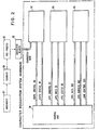
- FIG. 2 is a schematic block diagram of a hardware embodiment of a character recognition system according to the present invention.
- the system includes a control unit 50, a bit-scan processor unit (BSPU) 52, an arithmetic processor unit (APU) 54 and a system memory unit (SMU) 56.
- Documents, represented by block 57 are scanned by a suitable scanner 58, for example an optical scanner, of a type available in the art.
- the scanned information is preprocessed into matrix form (column and row) by block 60 and is then entered into character memory means 62 in the form of digital signals representative of "black” and "white” character increments in the rows and columns of the matrix, which for purposes of explanation will be selected as sixty-four rows and sixty-four columns within character memory means 62 which itself is a large memory capable of storing many characters.
- United States patents number 3,229,100, number 3,248,699, and number 3,500,325 also relate to curve following and processing.
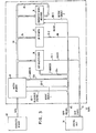
- the character information stored in character memory means 62 is entered into the bit-scan processor unit (BSPU) 52 which is shown in more detail in FIG. 3.
- the BSPU 52 stores the scanned character in a N-words (rows) by N-bits (columns) matrix memory 64 where N is selected as sixty-four in the present example and each of the 4096 bit positions is referred to as having either a "black” or "white” bit stored therein.
- Any row of matrix memory 64 and any bit within any row of matrix memory 64 can be selected by means of a six-bit y-address signal and a six-bit x-address signal on cable 66.
- the y-address is applied via cable section 66y to matrix memory 64 which selects a designated row.
- the selected sixty-four bit row is transferred via cable 68 to a bit-multiplexer 76.
- the x-address signal is applied via cable section 66x to bit multiplexer 76 to select a desired bit position of the previously selected row.
- the resultant output B(x,y) from bit-multiplexer 76 is the signal stored at the selected bit position whose coordinates are x and y of the address and is transmitted to control unit 50 via line 74-1 of gable 74 to provide a status signal, to be later described.
- the character to be processed is obtained from the character memory 62 and is stored as an array of bits (black and white) within the 4096 bit matrix memory 64 having sixty-four columns and sixty-four rows. In addition to the identity of the character, it is also not known whether the character fills the entire matrix, or whether it is smaller in size and occupies the lower right hand area of the matrix, for example.
- the first step in the process is to determine the character boundaries, that is, the extreme top and bottom and the left and right black bits so as to provide an indication of character size and its position within the matrix.
- the character recognition process in the system being described employs feature scan parameters which include four elements: START (S), LENGTH (L), TRANSITION NUMBER (TN) and ROTATION (R). These four elements of each feature scan parameter are employed in extracting the features of a particular character. Initially, the START (S) and the LENGTH (L) parameters must be adjusted or de- normalised to conform with the boundaries (size and location) of the particular character in the matrix memory 64. The TN and R parameters do not have to be adjusted.
- the character bit matrix memory 64 is first sequentially interrogated from either the top down or from the bottom up. In this example, the matrix memory 64 will be interrogated from the top down (i.e., row 63 to row 0).
- Control unit 50 provides the sequence of y address signals on section 66y of cable 66. The y address is initially set to row number sixty-three and is then decremented. As each sixty-four bit row is accessed it is transferred via cables 68 and 70 to "Or" network 72 which is a sixty-four input OR circuit whose output, BB, on line 742 ⁇ of cable 74 takes the value "1" when any inputs are "1" (black) bits.
- the output BB of network 72 is connected back to control unit 50 via cable 74.to provide a status signal.
- the output BB of the OR network will take on the value of "1", indicating that the top boundary of the character in matrix memory 64 has been located.
- the output of "Or” network 72 informs control unit 50 of this occurrence and the particular y-address of the row for the top boundary of the character in matrix memory 64 is specified. Control unit 50 enters this information (y-address) in the system memory unit (SMU) 56 (FIG. 2).
- character-width register'78 is a sixty-four bit storage register which stores the bits from each row of matrix memory 64 as the matrix memory 64 is decremented. Each succeeding row from matrix memory 64 is read on over the previously stored row in character-width register 78.
- a storage cell once set to the "1" state, can only be reset to the "0" state by means of the "CLEAR" line of cable 66.
- Output Enable 1 of cable 66 is set to zero thereby effectively disconnecting the output of said memory from cable 68.
- the single composite row of data stored in character-width register 78 is inserted into cable 80 via a "1" signal on Output Enable. 2 of cable 66 and thereby said data appears at the input to Bit-Multiplexer 76.
- control unit 50 When the first black bit is encountered during decrementation, this specifies the extreme right side of the character and the x- ⁇ address of this bit is sent to system memory 56 from control unit 50.
- Control unit 50 thus sends the left- and right-bit addresses (from which the character width is derived) to the system memory unit 56 (FIG. 2).
- the character size and its relative position within the sixty-four by sixty-four matrix 61 may now be determined from the upper-boundary y-address, lower- boundary y-address, left-boundary x-address and the right-boundary x-address stored in system memory unit 56.
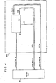
- FIG. 4 is a schematic block diagram of one embodiment of the structure for the arithmetic processor unit (APU) 54 previously illustrated and described relative to FIG. 2.
- the arithmetic processor unit 54 includes: arithmetic logic unit and working register file (RALU) 80 which is connected to control unit 50 by means of APU control bus 82; data control bus 84, data input bus 86, both of which are connected to APU data bus 90; and, APU status bus 88.
- arithmetic logic unit and working register file (RALU) 80 which is connected to control unit 50 by means of APU control bus 82; data control bus 84, data input bus 86, both of which are connected to APU data bus 90; and, APU status bus 88.
- Standard logic and arithmetic processing functions such as addition, subtraction, multiplication, division, comparison, et al, are carried out by the arithmetic processor unit 54. as required under direction of control unit 50.
- the particular processing function to be executed, the data sources for the processing function and destinations for the results are governed by the commands received from control unit 50 via APU control bus 82.
- These APU function and register select commands come from control word register 120 of control unit 50 which will be more fully described with reference to FIGS. 6A and 6B.
- arithmetic-processing commands are received from a control word register (CWR) field (CWRF4) of the control word register 120 of FIG. 6A and are coupled to the arithmetic processor unit 54 via the APU control bus 82 as shown in FIG. 4 and again in FIG. 6B.
- CWR control word register
- CWRF4 control word register
- the logic and arithmetic processing functions include addition, subtraction, multiplication, division, comparison, et al; and these are performed in various phases of system operation as they are needed such as in the determining of the character height and width and location within the character bit matrix, in the denormalization of the scan and length parameters accumulating scan arc-lengths during curve followings, computing complex inner products to determine which canonic shape best matches a given extracted feature, coding of the extracted and matched feature information, etc.
- Design details of the instructions set formats, form and formats of data words, operational sequences of micro instructions to perform required arithmetic functions, etc., are omitted since these are within the capabilities of one skilled in the design of the implementation of the arithmetic processor unit 80.
- the data upon which the various arithmetic processing functions such as addition, subtraction, multiplication, etc. are carried out by arithmetic processor unit 80 are provided on bus 90 and data input bus 86 and the results of the arithmetic processing are removed from arithmetic processor unit 80 via data output bus 84 and bus 90.
- the data is transferred to and from system memory unit (SMU) 56 under the direction of signal commands from control unit 50.
- SMU system memory unit
- the third connection between the arithmetic processor unit 54 and control unit 50 is the APU status bus 88 which is connected to the status condition multiplexor 140 (FIG. 6A) of the control unit 50.
- Status condition multiplexor 140 is controlled by signals from field (CWRF2) of control word register 120.
- the arithmetic processor unit 54 depicted in FIG. 4 is the unit which carries out the logical and mathematical functions required throughout the system operation.
- the arithmetic processor unit 54 operates under the command of control unit 50 and obtains and returns the required data from the system memory unit 56 under the control of signals from control unit 50.
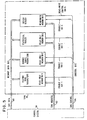
- FIG. 5 depicts a schematic block diagram of one embodiment of the structure for the system memory unit (SMU) 56.
- the system memory unit 56 is divided into four sub-units which include read-only memory 56-1 in which are stored the feature scan parameters provided by the "Select and Store Feature Scan Parameters" function 10-2 described relative to FIG. 1.
- Read-only memory 56-2 contains canonic shape parameter information provided by the "Select and Store Canonic Shape Parameters" function 10-3 described relative to FIG. 1.
- Read-only memory 56-3 contains statistical tables created by the "Build Statistical Table” function 20-2 of FIG. 1 and read-write memory 56-4 contains the general system memory space.
- SMU address bus 102 from control unit 50, is connected to the address input of each of the four memory sub-units within system memory unit 56.
- Control of the system memory unit 56 under direction of control unit 50 is accomplished by means of appropriate commands fed to the system memory unit via SMU control bus 104.
- SMU control bus 104 includes individual enable lines for each of the four memory sub-units (enable 104-1 through enable 104-4). Mode control of read-write memory 56-4. is determined by read-write control line 104-5.
- the system memory unit 56 depicted in FIG. 5 is a system storage means which may be embodied in conventional memory hardware.
- the SMU 56 is divided into four sub-units: three read-only memory portions 56-1, 56-2 and 56-3 which serve to provide storage for the feature scan parameters, the canonic shape parameters and. the statistical tables, and a read-write memory portion 56-4 which is the general memory space for other data employed during the system operation such as the outputs from the arithmetic processor unit 54.
- the system memory unit 56 is connected to and operates under the supervision of control unit 50 via the aforesaid busses 100, 102 and 104.
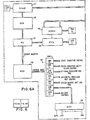
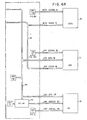
- FIGS. 6A and 6B when combined as shown in FIG. 6, illustrate a schematic block diagram of one embodiment of a structure for control unit 50.
- Control unit 50 is connected to and controls the operations of the functions of the bit-scan processor unit 52, the arithmetic processor unit 54 and the system memory unit 56.
- the control unit includes the System Control Memory Address Register (SCMAR) 110, System Control Memory (SCM) 112 a read-only memory in which is stored the system control program, Microprogram Sequencer (MS) 114, a read-only memory 116 containing the Microprogram Control Memory (MCM) 116, State Transition Control Network (STCN) 118, Control Word Register (CWR) 120, Bus Control and Clock Distribution network (BCCD) 138, Status Condition Multiplexer (SCMPX) 140, System Memory Unit Address Register (SMUAR) 142, Data Bus 144 and Status Bus 146.
- SCMAR System Control Memory Address Register
- SCM System Control Memory
- MS Microprogram Sequencer
- MCM Microprogram Control Memory
- STCN State Transition Control Network
- BCCD Bus Control and Clock Distribution network
- SCMPX Status Condition Multiplexer
- SMUAR System Memory Unit Address Register
- control work register 120 The individual control field designations in control work register 120 are as follows: F1, which is allocated for state transition control; F2, which is allocated for status condition multi- lexer control; F3, which is allocated for bit scan processor control; F4, which is allocated for arithmetic processor unit control; F5, which is allocated for system memory unit control; F6, which is allocated for bus control and clock distribution; and field F7 is allocated for register controls
- Control Unit 50 is a read-only memory (ROM)-based microprogrammed digital control system that generates an ensemble of time-sequenced control waveforms on the output lines of Control Word Register 120 which are used to direct and coordinate the interrelated operations of the various hardware sub-units, i.e., Bit-Scan Processor Unit (BSPU) 52, et al, in performing specified system operations. These system operations are performed by executing appropriate sequences of system-level commands stored in System Control Memory (SCM) 112 and addressed by the System Control Memory Address Register (SCMAR) 110.
- SCM System Control Memory
- SCMAR System Control Memory Address Register
- Execution of a system-level command begins by fetching said command from SCM 112 and loading it into MS 114 which utilizes said command as an address pointer into MCM 116 to fetch the first of a sequence of binary-coded control words that will be successiveively loaded into CWR 120, thereby generating time-sequenced control waveforms at the various bit- positions within CWR 120 to control interrelated operations within hardware sub-units as required to carry out said system-level command.
- System Control Memory 112 is a read-only memory in which is stored the system-level control information comprising sequences of binary-coded system-level commands, chosen from a suitably defined set of such commands. These sequences of system-level commands are appropriately related to the collection of algorithms or procedures previously described. The specification of a suitable system-level command set, their assigned binary encodings, and said appropriately related sequences thereof is within the capabilities of one skilled in the design of ROM-based microprogrammed digital control systems. Several references describing the design of ROM-based microprogrammed digital systems are given as follows:
- each system-level command in the specified command set is examined from an operational viewpoint to determine the time-sequenced actions required of the hardware sub-units in order to execute or carry out said system-level command.
- each system-level command is analyzed and described in terms of a corresponding sequence of interrelated elemental hardware operations that are to take place within various hardware sub-units.
- each sequence of interrelated elemental hardware operations corresponding to a given system-level command, that takes place within a given hardware sub-unit is analyzed to define the requisite time-sequenced control waveforms needed as control inputs to said hardware sub-unit to elicit said sequence of interrelated elemental hardware operations therefrom.
- This procedure is applied, in turn, for each of the hardware sub-units to create a complete description of the required ensemble of control waveforms.
- Each control waveform so defined establishes a sequence of time-dependent signal values required as part of the control input from CWR 120 to a hardware sub-unit. From the sequence of signal values, comprising binary digit (bit) values of "0" and "1”, in turn is derived the sequence of bit values and associated time durations required at a given particular output bit-position of CWR 120. The collection of all such information, for all the bit- positions within CWR 120, provides the basis on which to synthesize the binary coded control words that are to be loaded into permanent (ROM) storage, provided by MCM 116.
- ROM permanent
- the remainder of CU 50 is implemented using industry-standard microprogrammable bit-slice LSI digital circuits such as the 2900- series of devices from Advanced Micro Devices (AMD), Inc., the 9400-series from Fairchild Semiconductor, Inc., the 3000-series from Intel, Inc., the 74S400-series from Texas Instruments (T.I.), Inc., etc., and MSI circuits such as the 7400-series TTL circuits available from many sources.
- AMD Advanced Micro Devices
- FAD Fairchild Semiconductor
- MSI circuits such as the 7400-series TTL circuits available from many sources.
- MSI and LSI devices are listed below are some specific examples of MSI and LSI devices that may be used for implementation of various portions of CU 50.
- PROMs programmable ROMs
- Microprogram Sequencer 114 Am2909's available from AMD, Inc., or 74S482's available from T.I., Inc.
- Control Word Register 120 AM2918's from AMD, Inc.
- Bus Control and Clock Distribution 138 82S123 PROMs from Signetics, Inc., and 74112, 74124 and 74161 MSI circuits, et al, available from AMD, Ti., Signetics, etc.
- Microprogram Control Memory (MCM) 116 is a read-only memory that contains bit patterns, organized as control words, which are addressed by the Microprogram Sequencer (MS) 114. By addressing appropriate locations in MCM 116 in a suitable sequence, the required time-sequenced control waveforms will be emitted to the hardware sub-units from CWR 120.
- MS 114 will point to, i.e., issue the address of, the initial control word required at the output of CWR 120.
- This control word is loaded from MCM 116 into CWR 120 and initiates some elemental operation(s) to begin the sequence of interrelated hardware actions required of the hardware sub-unit(s) in order to begin carrying out said current system-level command. Selection of the address of the next control word to be accessed from MCM 116 is determined by control information stored in field 1 (F1) of CWR 120.
- This state transition control (STC) information defines how the address of the next control word to be accessed from MCM 116 will be determined and provides the basis for Control Unit 50 to perform useful functions by progressing through prescribed state sequences in a controlled manner.
- State Transition Control Network (STCN) 118 decodes the STC information residing in F1 of the current . control word in CWR 120 and provides control and data inputs to MS 114.
- STCN State Transition Control Network
- STC information in CWR F1 commands STCN 118 to utilize the information from Status Condition Multiplexer (SCMPX) 140 in generating the control input to MS 114.
- SCMPX 140 Status Condition Multiplexer
- CWRF2 control input to SCMPX 140 defines which of the status condition feedback lines shall be coupled to STCN 118 and specifies if logic inversion of that status signal is required.
- the selection of the next control word in MCM 116 can be made to depend on the status of signals within hardware sub-units so that, for example, if a selected status condition is true the MS 114 will increment the memory address pointer and if said condition is found to be false, STCN 118 will load a branch address into the memory address pointer (in MS 114) from F1 of the current control word residing in CWR 120.
- the selection of the next control word in MCM 116 is made to depend upon the status of a condition within a hardware sub-unit and thereby provides the ability for CU 50 to test status conditions and to branch appropriately within the microprogram memory space.
- control information contained in F1 of the final control word related to said sequence residing in CWR 120 is decoded by STCN 118 to generate appropriate control input to MS 114 to cause it to read the next system-level command present at the output port of System Control Memory 112, said next system-level command having been updated after the MS 114 read the previous system-level command, viz., the system-level command just executed.
- MS 114 interprets the bit pattern of the new system-level command to determine the location, in MCM 116, of the first control word corresponding thereto and required to begin execution of said new system-level command.
- Bit pattern interpretation is accomplished by means of a read-only memory or programmed logic array, internal to MS 114, which maps the binary pattern of a given system-level command into the appropriate starting address for the corresponding first control word which is then loaded into CWR 120.
- Sequential control of the various phases within the process of executing system-level commands is the task assigned to the Bus Control and Clock Distribution network (BCCD) 138' which emits appropriately timed control signals to various parts of the system.
- BCCD Bus Control and Clock Distribution network
- Addresses for SCM 112 are supplied from SCMAR 110 under control of F7 of CWR 120.
- Fields F3A, F4 and F5 of CWR 120 provide control waveforms to the BSPU 52, APU 54 and SMU 56, respectively.
- F6 of CWR 120 provides control inputs to BCCD 138 to effect appropriate synchronization of interrelated hardware operations.
- F7 of CWR 120 also provides control inputs to SMUAR 142 (in addition to SCMAR 110) which supplies addressing for the memory sub-units, viz., ROMs 56-1, 56-2, 56-3 and Read/Write Memory 56-4. located in SMU 56.
- CBMM Character Bit-Matrix Memory
- the "locate top boundary" system-level command is received by MS 114 from the data output port of SCM 112 and is intercepted by an internal ROM look-up table to produce the address of the first control word in MCM 116.
- CBMM 64 is commanded by F3A of CWR 120 to enable the output of CBMM 64 and to place it in the read mode.
- a data path from output line BB 74-2 of the 64-to-1 OR network 72 to STCN 118 is established by appropriate control information in F1 of CWR 120 fed to SCMPX 140.
Landscapes
- Engineering & Computer Science (AREA)
- Physics & Mathematics (AREA)
- General Physics & Mathematics (AREA)
- Multimedia (AREA)
- Theoretical Computer Science (AREA)
- Computer Vision & Pattern Recognition (AREA)
- Databases & Information Systems (AREA)
- Character Discrimination (AREA)
Claims (7)
Applications Claiming Priority (2)
| Application Number | Priority Date | Filing Date | Title |
|---|---|---|---|
| US05/919,535 US4177448A (en) | 1978-06-26 | 1978-06-26 | Character recognition system and method multi-bit curve vector processing |
| US919535 | 1978-06-26 |
Publications (3)
| Publication Number | Publication Date |
|---|---|
| EP0006476A2 EP0006476A2 (fr) | 1980-01-09 |
| EP0006476A3 EP0006476A3 (en) | 1980-01-23 |
| EP0006476B1 true EP0006476B1 (fr) | 1983-01-12 |
Family
ID=25442270
Family Applications (1)
| Application Number | Title | Priority Date | Filing Date |
|---|---|---|---|
| EP79101709A Expired EP0006476B1 (fr) | 1978-06-26 | 1979-06-01 | Appareil de reconnaissance de caractères utilisant un traitement de vecteurs de courbure |
Country Status (5)
| Country | Link |
|---|---|
| US (1) | US4177448A (fr) |
| EP (1) | EP0006476B1 (fr) |
| JP (1) | JPS5948434B2 (fr) |
| CA (1) | CA1109154A (fr) |
| DE (1) | DE2964469D1 (fr) |
Families Citing this family (32)
| Publication number | Priority date | Publication date | Assignee | Title |
|---|---|---|---|---|
| US4760604A (en) * | 1985-02-15 | 1988-07-26 | Nestor, Inc. | Parallel, multi-unit, adaptive, nonlinear pattern class separator and identifier |
| DE3686051T2 (de) * | 1985-11-27 | 1992-12-17 | Univ Boston | Mustererkennungssystem. |
| US5142593A (en) * | 1986-06-16 | 1992-08-25 | Kabushiki Kaisha Toshiba | Apparatus and method for classifying feature data at a high speed |
| US4972496A (en) * | 1986-07-25 | 1990-11-20 | Grid Systems Corporation | Handwritten keyboardless entry computer system |
| US6002799A (en) * | 1986-07-25 | 1999-12-14 | Ast Research, Inc. | Handwritten keyboardless entry computer system |
| US5157737A (en) * | 1986-07-25 | 1992-10-20 | Grid Systems Corporation | Handwritten keyboardless entry computer system |
| US4821333A (en) * | 1986-08-22 | 1989-04-11 | Environmental Research Inst. Of Michigan | Machine learning procedures for generating image domain feature detector structuring elements |
| FR2604004B1 (fr) * | 1986-09-11 | 1990-05-11 | Anatex | Procede de reconnaissance d'ecriture manuscrite |
| US4850026A (en) * | 1987-10-13 | 1989-07-18 | Telecommunications Laboratories Dir. Gen'l Of Telecom. Ministry Of Communications | Chinese multifont recognition system based on accumulable stroke features |
| EP0312905B1 (fr) * | 1987-10-16 | 1992-04-29 | Computer Gesellschaft Konstanz Mbh | Procédé de reconnaissance automatique de caractères |
| US5072452A (en) * | 1987-10-30 | 1991-12-10 | International Business Machines Corporation | Automatic determination of labels and Markov word models in a speech recognition system |
| US4975975A (en) * | 1988-05-26 | 1990-12-04 | Gtx Corporation | Hierarchical parametric apparatus and method for recognizing drawn characters |
| US5131053A (en) * | 1988-08-10 | 1992-07-14 | Caere Corporation | Optical character recognition method and apparatus |
| EP0363828B1 (fr) * | 1988-10-11 | 1999-01-07 | Kabushiki Kaisha Ouyo Keisoku Kenkyusho | Procédé et dispositif de mesure et reconnaissance d'images universelles avec apprentissage adaptatif |
| JP2810152B2 (ja) * | 1989-10-13 | 1998-10-15 | 株式会社日立製作所 | ポイントパターンマッチング方法 |
| US5303311A (en) * | 1990-03-12 | 1994-04-12 | International Business Machines Corporation | Method and apparatus for recognizing characters |
| US5105470A (en) * | 1990-03-12 | 1992-04-14 | International Business Machines Corporation | Method and system for recognizing characters |
| EP0500315B1 (fr) * | 1991-02-18 | 1999-07-21 | Sumitomo Cement Co. Ltd. | Procédé de reconnaissance et classification optique de formes |
| US5150425A (en) * | 1991-08-30 | 1992-09-22 | Eastman Kodak Company | Character recognition method using correlation search |
| US5159644A (en) * | 1991-08-30 | 1992-10-27 | Eastman Kodak Company | Character recognition method using statistically weighted correlation |
| US5479533A (en) * | 1992-02-28 | 1995-12-26 | Yamatake-Honeywell Co., Ltd. | Pattern recognition apparatus and method using fuzzy logic |
| US5319721A (en) * | 1992-04-14 | 1994-06-07 | International Business Machines Corporation | Methods and apparatus for evolving a starter set of handwriting prototypes into a user-specific set |
| WO1995010820A1 (fr) * | 1993-10-15 | 1995-04-20 | At & T Corp. | Procedes et appareils de classification d'images a l'aide de cartes de repartition |
| EP0694862A3 (fr) * | 1994-07-22 | 1996-07-24 | At & T Corp | Reconnaissance de documents à niveaux de gris dégradés avec des pseudo-modèles de Markov cachés et à deux dimensions et avec des hypothèses de N meilleurs |
| US5802207A (en) * | 1995-06-30 | 1998-09-01 | Industrial Technology Research Institute | System and process for constructing optimized prototypes for pattern recognition using competitive classification learning |
| US6081621A (en) * | 1996-10-01 | 2000-06-27 | Canon Kabushiki Kaisha | Positioning templates in optical character recognition systems |
| RU2133501C1 (ru) * | 1998-02-04 | 1999-07-20 | Военная академия связи | Способ и устройство распознавания классов сигналов |
| US7162694B2 (en) * | 2001-02-13 | 2007-01-09 | Microsoft Corporation | Method for entering text |
| CA2375355A1 (fr) | 2002-03-11 | 2003-09-11 | Neo Systems Inc. | Systeme et methode de reconnaissance de caracteres |
| GB0227329D0 (en) * | 2002-11-22 | 2002-12-31 | Electrosonic Ltd | Image scanning |
| US9870520B1 (en) * | 2013-08-02 | 2018-01-16 | Intuit Inc. | Iterative process for optimizing optical character recognition |
| CN113127637B (zh) * | 2019-12-31 | 2025-09-02 | 中兴通讯股份有限公司 | 一种字符的还原方法及装置、存储介质、电子装置 |
Family Cites Families (9)
| Publication number | Priority date | Publication date | Assignee | Title |
|---|---|---|---|---|
| GB1245093A (en) * | 1967-12-07 | 1971-09-02 | Post Office | Improvements in or relating to pattern recognition apparatus |
| GB1333916A (en) * | 1970-11-18 | 1973-10-17 | Emi Ltd | Pattern recognition devices |
| JPS604505B2 (ja) * | 1972-07-10 | 1985-02-04 | スキヤン − オプテイクス インコ−ポレ−テツド | マルチ・フオント光学式文字認識装置 |
| US3979722A (en) * | 1974-05-31 | 1976-09-07 | Nippon Electric Company, Ltd. | Automatic character recognition device employing dynamic programming |
| JPS5428248B2 (fr) * | 1974-10-21 | 1979-09-14 | ||
| JPS51112236A (en) * | 1975-03-28 | 1976-10-04 | Hitachi Ltd | Shape position recognizer unit |
| NL165863C (nl) * | 1975-06-02 | 1981-05-15 | Nederlanden Staat | Inrichting voor het herkennen van tekens. |
| GB1587613A (en) * | 1976-11-04 | 1981-04-08 | Norprint Ltd | Character identification |
| DE2822458C2 (de) * | 1977-05-23 | 1983-11-03 | Sharp K.K., Osaka | Einrichtung zum Erkennen von Schriftzeichen |
-
1978
- 1978-06-26 US US05/919,535 patent/US4177448A/en not_active Expired - Lifetime
-
1979
- 1979-03-20 CA CA323,851A patent/CA1109154A/fr not_active Expired
- 1979-05-30 JP JP54066251A patent/JPS5948434B2/ja not_active Expired
- 1979-06-01 EP EP79101709A patent/EP0006476B1/fr not_active Expired
- 1979-06-01 DE DE7979101709T patent/DE2964469D1/de not_active Expired
Also Published As
| Publication number | Publication date |
|---|---|
| EP0006476A3 (en) | 1980-01-23 |
| JPS556695A (en) | 1980-01-18 |
| CA1109154A (fr) | 1981-09-15 |
| US4177448A (en) | 1979-12-04 |
| JPS5948434B2 (ja) | 1984-11-26 |
| EP0006476A2 (fr) | 1980-01-09 |
| DE2964469D1 (en) | 1983-02-17 |
Similar Documents
| Publication | Publication Date | Title |
|---|---|---|
| EP0006476B1 (fr) | Appareil de reconnaissance de caractères utilisant un traitement de vecteurs de courbure | |
| US4603431A (en) | Method and apparatus for vectorizing documents and symbol recognition | |
| Preston et al. | Basics of cellular logic with some applications in medical image processing | |
| US4167728A (en) | Automatic image processor | |
| EP0183347B1 (fr) | Système de reconnaissance d'images vidéo | |
| US4183013A (en) | System for extracting shape features from an image | |
| US4493105A (en) | Method and apparatus for visual image processing | |
| EP0114250B1 (fr) | Groupement de traits dans des catégories de confusion dans une méthode et un système pour la reconnaissance de formes | |
| Klinger | Data structures and pattern recognition | |
| EP0542566B1 (fr) | Procédé et appareil de reconnaissance de caractères | |
| US5923778A (en) | Hierarchical representation of reference database for an on-line Chinese character recognition system | |
| Mitchell et al. | A model-based computer vision system for recognizing handwritten ZIP codes | |
| US5359697A (en) | Fuzzy associative memory | |
| Kruse et al. | From PICAP I to PICAP II | |
| US4797941A (en) | Pattern detection in two dimensional signals | |
| Ledley | Analysis of cells | |
| Lazzerini et al. | A linguistic fuzzy recogniser of off-line handwritten characters | |
| Zhong | Flower recognition system based on YOLOv8 algorithm | |
| JPS6321232B2 (fr) | ||
| Kateman | Computers in analytical chemistry | |
| Woodward et al. | Computer controlled television scan system for direct encoding of chemical structure models | |
| Kasif | Optimal parallel algorithms for quadtree problems | |
| CA1256214A (fr) | Methode et appareil de vectorisation de documents et de reconnaissance de symboles | |
| KR900007727B1 (ko) | 문자 인식 장치 | |
| Degadwala et al. | Offline Gujarati Word Categorization Using Machine Learning Approach |
Legal Events
| Date | Code | Title | Description |
|---|---|---|---|
| PUAI | Public reference made under article 153(3) epc to a published international application that has entered the european phase |
Free format text: ORIGINAL CODE: 0009012 |
|
| PUAL | Search report despatched |
Free format text: ORIGINAL CODE: 0009013 |
|
| AK | Designated contracting states |
Designated state(s): CH DE FR GB IT NL |
|
| AK | Designated contracting states |
Designated state(s): CH DE FR GB IT NL |
|
| 17P | Request for examination filed | ||
| GRAA | (expected) grant |
Free format text: ORIGINAL CODE: 0009210 |
|
| AK | Designated contracting states |
Designated state(s): CH DE FR GB IT NL |
|
| PG25 | Lapsed in a contracting state [announced via postgrant information from national office to epo] |
Ref country code: NL Effective date: 19830112 Ref country code: IT Free format text: LAPSE BECAUSE OF FAILURE TO SUBMIT A TRANSLATION OF THE DESCRIPTION OR TO PAY THE FEE WITHIN THE PRESCRIBED TIME-LIMIT;WARNING: LAPSES OF ITALIAN PATENTS WITH EFFECTIVE DATE BEFORE 2007 MAY HAVE OCCURRED AT ANY TIME BEFORE 2007. THE CORRECT EFFECTIVE DATE MAY BE DIFFERENT FROM THE ONE RECORDED. Effective date: 19830112 |
|
| REF | Corresponds to: |
Ref document number: 2964469 Country of ref document: DE Date of ref document: 19830217 |
|
| ET | Fr: translation filed | ||
| NLV1 | Nl: lapsed or annulled due to failure to fulfill the requirements of art. 29p and 29m of the patents act | ||
| PG25 | Lapsed in a contracting state [announced via postgrant information from national office to epo] |
Ref country code: CH Effective date: 19830630 |
|
| REG | Reference to a national code |
Ref country code: CH Ref legal event code: PL |
|
| PGFP | Annual fee paid to national office [announced via postgrant information from national office to epo] |
Ref country code: GB Payment date: 19900516 Year of fee payment: 12 |
|
| PGFP | Annual fee paid to national office [announced via postgrant information from national office to epo] |
Ref country code: FR Payment date: 19900529 Year of fee payment: 12 |
|
| PGFP | Annual fee paid to national office [announced via postgrant information from national office to epo] |
Ref country code: DE Payment date: 19900707 Year of fee payment: 12 |
|
| PG25 | Lapsed in a contracting state [announced via postgrant information from national office to epo] |
Ref country code: GB Effective date: 19910601 |
|
| GBPC | Gb: european patent ceased through non-payment of renewal fee | ||
| PG25 | Lapsed in a contracting state [announced via postgrant information from national office to epo] |
Ref country code: FR Effective date: 19920228 |
|
| PG25 | Lapsed in a contracting state [announced via postgrant information from national office to epo] |
Ref country code: DE Effective date: 19920401 |
|
| REG | Reference to a national code |
Ref country code: FR Ref legal event code: ST |
|
| PLBE | No opposition filed within time limit |
Free format text: ORIGINAL CODE: 0009261 |
|
| STAA | Information on the status of an ep patent application or granted ep patent |
Free format text: STATUS: NO OPPOSITION FILED WITHIN TIME LIMIT |