EP0006508A1 - Bande d'étanchéité et dispositif d'équilibrage pour fenêtres - Google Patents
Bande d'étanchéité et dispositif d'équilibrage pour fenêtres Download PDFInfo
- Publication number
- EP0006508A1 EP0006508A1 EP79101835A EP79101835A EP0006508A1 EP 0006508 A1 EP0006508 A1 EP 0006508A1 EP 79101835 A EP79101835 A EP 79101835A EP 79101835 A EP79101835 A EP 79101835A EP 0006508 A1 EP0006508 A1 EP 0006508A1
- Authority
- EP
- European Patent Office
- Prior art keywords
- sash
- weather strip
- mounting
- assembly according
- balance
- Prior art date
- Legal status (The legal status is an assumption and is not a legal conclusion. Google has not performed a legal analysis and makes no representation as to the accuracy of the status listed.)
- Withdrawn
Links
- 230000000712 assembly Effects 0.000 title claims abstract description 11
- 238000000429 assembly Methods 0.000 title claims abstract description 11
- 230000006835 compression Effects 0.000 claims 1
- 238000007906 compression Methods 0.000 claims 1
- 230000008878 coupling Effects 0.000 abstract description 3
- 238000010168 coupling process Methods 0.000 abstract description 3
- 238000005859 coupling reaction Methods 0.000 abstract description 3
- 238000007789 sealing Methods 0.000 abstract description 2
- 230000013011 mating Effects 0.000 abstract 1
- 238000009434 installation Methods 0.000 description 11
- 238000004519 manufacturing process Methods 0.000 description 4
- 238000004140 cleaning Methods 0.000 description 2
- 239000007769 metal material Substances 0.000 description 2
- 238000004873 anchoring Methods 0.000 description 1
- 238000005452 bending Methods 0.000 description 1
- 239000002131 composite material Substances 0.000 description 1
- 238000010276 construction Methods 0.000 description 1
- 230000003467 diminishing effect Effects 0.000 description 1
- 238000006073 displacement reaction Methods 0.000 description 1
- 230000000694 effects Effects 0.000 description 1
- 238000012423 maintenance Methods 0.000 description 1
- 229920003023 plastic Polymers 0.000 description 1
- 230000000717 retained effect Effects 0.000 description 1
- 238000000926 separation method Methods 0.000 description 1
- 229920002554 vinyl polymer Polymers 0.000 description 1
Images


Classifications
-
- E—FIXED CONSTRUCTIONS
- E06—DOORS, WINDOWS, SHUTTERS, OR ROLLER BLINDS IN GENERAL; LADDERS
- E06B—FIXED OR MOVABLE CLOSURES FOR OPENINGS IN BUILDINGS, VEHICLES, FENCES OR LIKE ENCLOSURES IN GENERAL, e.g. DOORS, WINDOWS, BLINDS, GATES
- E06B3/00—Window sashes, door leaves, or like elements for closing wall or like openings; Layout of fixed or moving closures, e.g. windows in wall or like openings; Features of rigidly-mounted outer frames relating to the mounting of wing frames
- E06B3/32—Arrangements of wings characterised by the manner of movement; Arrangements of movable wings in openings; Features of wings or frames relating solely to the manner of movement of the wing
- E06B3/50—Arrangements of wings characterised by the manner of movement; Arrangements of movable wings in openings; Features of wings or frames relating solely to the manner of movement of the wing with more than one kind of movement
-
- E—FIXED CONSTRUCTIONS
- E05—LOCKS; KEYS; WINDOW OR DOOR FITTINGS; SAFES
- E05D—HINGES OR SUSPENSION DEVICES FOR DOORS, WINDOWS OR WINGS
- E05D13/00—Accessories for sliding or lifting wings, e.g. pulleys, safety catches
- E05D13/10—Counterbalance devices
- E05D13/12—Counterbalance devices with springs
- E05D13/1207—Counterbalance devices with springs with tension springs
-
- E—FIXED CONSTRUCTIONS
- E05—LOCKS; KEYS; WINDOW OR DOOR FITTINGS; SAFES
- E05D—HINGES OR SUSPENSION DEVICES FOR DOORS, WINDOWS OR WINGS
- E05D15/00—Suspension arrangements for wings
- E05D15/16—Suspension arrangements for wings for wings sliding vertically more or less in their own plane
- E05D15/22—Suspension arrangements for wings for wings sliding vertically more or less in their own plane allowing an additional movement
-
- E—FIXED CONSTRUCTIONS
- E05—LOCKS; KEYS; WINDOW OR DOOR FITTINGS; SAFES
- E05Y—INDEXING SCHEME ASSOCIATED WITH SUBCLASSES E05D AND E05F, RELATING TO CONSTRUCTION ELEMENTS, ELECTRIC CONTROL, POWER SUPPLY, POWER SIGNAL OR TRANSMISSION, USER INTERFACES, MOUNTING OR COUPLING, DETAILS, ACCESSORIES, AUXILIARY OPERATIONS NOT OTHERWISE PROVIDED FOR, APPLICATION THEREOF
- E05Y2900/00—Application of doors, windows, wings or fittings thereof
- E05Y2900/10—Application of doors, windows, wings or fittings thereof for buildings or parts thereof
- E05Y2900/13—Type of wing
- E05Y2900/148—Windows
Definitions
- This invention relates to a weather strip and balance assembly for a window having a tilt-type sash, and more particularly to a unitary weather strip and balance assembly which permits tilting of a sash on a weather strip while maintaining a positive seal between a sash and a weather strip for the normal sliding position of the sash.
- the weather strip and balance assemblies incorporated in both tilt and non-tilt type windows have been separate components which are combined upon installation of the same into a window with the sash.
- balance assemblies have been combined with a weather strip as a jamb liner
- the components have been separately manufactured and combined at the point of usage through specialized fastening devices to secure the same to a window frame.
- the use of individual components or separate structures combined at the point of installation have increased the expense of manufacture, storage and handling and the cost of installation of the same. More importantly, such structures have less flexibility in the mounting of a sash, particularly for tilt type windows, diminishing the effectiveness of the seal between the weather strip and the sash.
- a weather strip and balance assembly for a tilt-out sash window having a window frame including jambs and at least one sash having side stiles sliding in the side jambs of the window frame,said assembly being characterized by the combination of a jamb liner adapted to be positioned between the side stiles of the sash and the window frame jambs, each jamb liner comprising a weather strip having a ribbed surface adapted to slidably mount and seal to the side stiles of the sash, and with a recessed surface adjacent the same, and a mounting plate positioned behind and locked to the weather strip to permit flexing of the weather strip relative to the jambs of the window frame, a balance device positioned within each jamb liner, said balance device including a balance spring with a sash cord coupled thereto and directed over pulleys to apply tension of the balance spring to the sash, anchor means positioned within each jamb
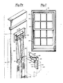
- FIG. 1 A firs preferred embodiment of the assembly is shown in Figure 1 as applied to a double hung window Indicated generally at 10.
- the window is comprised of a frame 15 having suitable trim, indicated generally at 20, mounted thereon, and the frame mounts a pair of sash 25, 30 which are slidably positioned in the frame on the side jambs thereof.
- the frame 15 has jambs 18 on which are positioned jamb liners 40 for purposes of mounting the sash thereon.
- the jamb liners have curved surfaces, as will be hereinafter noted, and the sash have corresponding grooves 45 in the stiles of the same to ride on the curved surfaces of the jamb liners 40.
- the sash are adapted to tilt out from the jamb liners for purposes of cleaning in a conventional manner.
- the jamb liners mount a balance system which does not include a locking structure to lock the balance system when the sash are tilted on the jamb liners. Frictional forces are relied on in this embodiment to hold the sash in position upon tilt.
- the jamb liners 40 combine a weather strip member 50 and balance assemblies as will be hereinafter noted.
- the weather strip 50 is preferably made of a polyvinyl or flexible metal material and may be extruded or otherwise formed as an elongated member which extends substantially the length and width of the window jamb.
- the weather strip has a pair of curved ridge members 52, 53 separated by a recessed center portion 54.
- the curved ridges 52, 53 mount the sash in the window frame and slidably support the same thereon.
- To either side of the rridges are recessed surfaces 54 which contribute to the flexibility of the weather strip and provide compressive as well as translational movement of the ridges in support of the sash to effect a seal therebetween.
- the ends of the weather strip are turned in as at 55.
- the undersurface of the weather strip adjacent the recessed portions 54 have translationally extending retaining tabs 56 formed integral thereon.
- the jamb liner includes a mounting plate 70 having a length dimension equal to the length of the weather strip member and a width dimension such as to fit between the ends 55 of the weather strip member.
- the mounting plate 70 is preferably made of a plastic or flexible metal material and it includes upstanding flanges 71 bent transverse the extent of the main body of the mounting plate with inclined flanges 72 at the ends of the same. As will be best seen in Figures 2, and 3, the flanges 72 fit around the tabs 56 on the undersurface of the weather strip to retain the weather strip on the mounting flange.
- the mounting flange is adapted to be positioned against the jamb of the window frame and secured thereto with the weather strip being snapped over the same and retained thereon.
- the weather strip member is flexible and generally bowed along its width such as to mount the sash in the window frame with the sash riding on the raised rib portions 52, 53 which fit in the grooves 45 in the stiles of the sash.
- the weather strip member may be compressed inwardly in the mounting of the sash in the window frame and the recesses 54 allow for translational movement to insure a proper fit of the sash on the curved ribbed portions 52, 53, and a positive seal therebetween.
- the recessed center portion 54 is generally rectangular in cross section, and as will be hereinafter noted, will mount or slidably position pins secured to the sash for retaining the sash on the weather strip.
- the mounting plate 70 mounts the balanc.e system for each sash and thece balance systems are located between the mounting plate and the undersurface of the weather strip as will be best seen in Figures a and 3.
- Each balance system is comprised of an elongated helical spring 75, 76, which are secured at one and respectively to brackets 78 riveted on the lower end of the mounting plate.
- the opposite end of each spring mounts a pulley member 80, 8l which couple sash cords to the springs.
- Each of the balance assemblies in the jamb liner include a separate sash cord indicated at 84, 85 respectively, which are secured at one end to a pulley mounting block 90 carried by the upper end of the mounting plate 70.
- the sash cord is directed over the pulleys 81, 82 on the ends of the springs 75, 76 and backed over pulleys indicated at 91, 92 respectively in the pulley mounting block with the free end of the respective sash cords being directed down the extent of the recessed center portion 54 on the outer surface of the weather strip.
- Suitable pin members 95, 96 respectively, are secured to the ends of the respective sash cords 84, 85 and are coupled to the sash, as will be hereinafter noted.
- the springs 75, 76, as well as the sash cords and pulley attached thereto, are located within the jamb liner behind the curved ridge portions 52, 53 such that the jamb liner may be compressed or removed for installation of the sash or upon tilt of the sash, will present no interference with the balance system components.
- One end of the mounting plate 70 in the area of the bracket members 78 securing one end of the springs to the mounting plate includes an aperture through which a screw 74 may be inserted to secure the mounting plate to a side jamb of a window frame.
- the pulley mounting block 90 is a plural part structure with the pulley members 91, 92 jour- naled therein and with apertures extending through the axles of the pulleys so that screw means 94 may be positioned therethrough to mount the upper end or opposite end of the mounting plate to the jamb of the window frame.
- the ends of the sash cords 84, 85 are tied or otherwise secured to the mounting block and a portion of the weather strip adjacent the mounting block has the recessed center portion cut away to permit exit of the sash cords to the face side of the weather strip such that the sash cords may be directed down the weather strip to the pin members 95, 96 which are slidably positioned in the recessed center portion 54.
- Pulley block is secured to the upper end of the mounting plate through a suitable rivet indicated at 98 which extends through the pulley block and secures the same to the upper end of the mounting plate in manufacture.
- the balance assemblies are mounted on and secured to the mounting plate as a composite unit with the weather strip snapped on to the mounting plate to complete the jamb liner.
- the jamb liner is secured through the mounting plate by the screws 74 and 94 to the jamb to install the same on a window frame.
- the mounting plate becomes load bearing upon installation and during manufacture, storage and shipment there is no load applied to the same through the balance system, such as to cause warpage or bending.
- the balance systems are connected to the respective sash through mounting blocks members which secure the ends of the pins 95, 96 to the sash.
- the lower sash 25 has a mounting member 100 positioned on the lower inside edge of the sash adjacent each of the jamb liners which mounting member has a generally rectangular or keyed recess 101 extending therethrough.
- the pin 95 has a head portion 97 which is generally cylindrical and through which an aperture 99 extends with the remainder of the pin having a cross-sectional dimension symmetrical with the aperture 101 in the mounting block such that this end of the pin will fit therethrough.
- Suitable mounting holes 104 are positioned in the block such that the same may be secured to the inner surface of the sash of the edges of the same.
- An additional aperture 105 is positioned therein and this aperture is adapted to receive a screw which extends through an aperture 102 in the pin 95 to secure the pin rigidly to the sash.
- Block 100 has inclined edges and a thickness dimension that is generally equal to the spacing between the sash as they are mounted on the respective curved surfaces 52, 53 of title jamb liner. Thus, the surface'of the upper sash will slide and bear against the block 100 as the upper sash is drawn down on the jamb liners.
- the upper sash 30 adjacent its lower outer surface or that facing the inner sash has a generally square block member 110 mounted at the lower edge of the same, the block member having a translationally extending flange portion 112 at the base of the same which fits the block member around the lower edge of the upper sash.
- Block member 110 is part of a sweep lock mechanism and a suitable aperture 114 in the face of the same is adapted to receive a sweep lock as will be hereinafter noted.
- Member 110 also includes a mounting portion 115 formed integral therewith and projecting along the surface of the same which portion has a recessed aperture 116 therein.
- the aperture 116 has a cross-section similar to a keyed portion of pin 96 which is similar to the surface of pin 95.
- Pin 96 also includes a head portion 97 adapted to ride in the recessed center portion 54 of the weather strip with an aperture 103 therein through which a sash cord extends.
- the pin 96 also has an aperture 106 - therein which is adapted to receive a mounting screw to secure the pin in the mounting portion 115 of block 110.
- the mounting block 110 also serves as a portion of a sash guide structure and has a projecting flange or tongue 118 on the edge of the same which cooperates with a similar grooved part in a sash guide and sweep lock member, indicated generally at 120, and mounted on the upper edge of the inner sash 25 on the inner surface thereof.
- the guide and lock member 120 has a downwardly extending guide flange portion 122 with a groove 123 therein designed to receive the tongue or flange portion 118 of the member 110.
- a transversely extending flange portion 125 fits across the top of the inner sash and the upper end of the guide and lock member has a recessed area 126 in which is positioned a pivoted sweep lock 128 having a camming head 129 on the end of the same designed to fit into the groove l14 in the member 110.
- the sash and guide member 120 is also grooved as at 130 at the surface adjacent the curved portion of the sash such that the groove corresponds with the grooved recess in the sash and mates with the ribbed surface 52 of the weather strip member.
- the flange 112 has a similar grooved surface (not shown) on the edge adjacent the edge of the sash and corresponding with the groove 45 in the sash such that it will ride on the ridge 53 of the weather strip.
- Both the members 110 and the guide and lock member 120 have suitable mounting holes, indicated at 132, therein through which screws are adapted to extend to mount the respective members on the sash.
- the thickness of the member 110 at the mounting portion is basically the same thickness as the mounting member 100 on the lower face of the lower sash and serves as a guide to hold the sash separated or spaced on the respective ribbed mounting portions 52, 53 of the weather strip.
- the weather strip member 50 may be removed from the mounting member 70 by translationally squeezing the ribbed portions 52, 53 together to release the flanges 56 from the flange portion 72 of the mounting member.
- the mounting member may then be positioned on the jamb surface of the window frame and the screws 94 and 74 installed to secure the mounting member to the jamb surface of the window frame.
- the weather strip may be snapped into position over the mounting member with the sash cords 84,. 85 brought out through the recess at the upper end of the same such that the sash cords with the pins 95, 96 on the ends of the same are located in the recessed center portion 94 of the weather strip.
- the mounting members 100, 110 and sash and guide member 120 are then installed on the surface of the respective sash adjacent the sides of the same.
- the pins 95 ray be inserted into the keyed aperture 101 of the mounting members and suitable screw means directed into the sash to secure the same therein.
- the weather strip will be displaced inwardly to bring the grooved sides of the stiles into position over the ribbed surface of the weather strip.
- the upper sash is similarly installed in the same manner with the pins 96 being directed through the apertures 116 in the mounting portions 115 of the members 110 on the outer surface of the upper sash and on the lower edges of the same.
- the weather strip may be similarly compressed to permit the positioning of the pins 96 in the recessed center portion as the sash is mounted on the ribbed surface 53 of the weatlier strip. Adjustment of spring tension for the respective sash will be effected prior to installation of the pins by applying tension to the springs through the sash cords and securing the pins on the ends of the sash cord at the respective points which will apply sufficient pressure at the raised and lowered position of the respective sashes.
- the sash When the sash are installed on the jamb liners, they may be pivoted away from the weather strip with the head portions 97 of the respective pins holding the pins in position on the jamb liner.
- the compressive and translational movement of the respective weather strip members permit displacement of the sash such that it may be tilted out for cleaning or maintenance purposes and returned to an aligned position for the weather strip and riding on the curved surface for the weather strip for sealing and guiding purposes.
- the improved weather strip and balance assembly does not include any provision for locking the balance assembly for tilt of the window in this embodiment.
- the window may move in a tilted position.
- normal frictional forces between the sash and the weather strip generally restrict such movement when the window is in a tilted position.
- the improved weather strip and balance assembly provides an arrangement in which the balance assembly is factory mounted and installed in the jamb liner so that it :nerely need be secured to the jamb and connected to the sash upon installation.
- the flexible ribbed surfaces 52, 53 of the weather strip bear against the grooved surfaces of the sash in all sliding positions to insure positive and dynamic seal under all conditions.
- the weather strip member permits translational movement of the ' ribbed surfaces in the installation and for alignment purposes.
- the mounting and sash guide members 110, 120 cooperate to lock the sash in a closed position on the weather strip to prevent tilt of the same and to permit operation of the sweep lock which will prevent separation of the sash.
- the improved system is relatively economical and easy to install.
- Figure 5 shows an alternate embodiment of the structure of Figures 1 through 4 in that it includes a locking provision for the balance assembly upon tilt of the sash. Since the backing plate and weather strip member together with the mounting of the balance assembly therein, is unchanged from the preferred embodiment, its details will be omitted for simplicity. Similarly, the mounting and guide members 100, 110 and 120 are identical with this embodiment in serving to guide the sash, mount the pins to secure the balance assemblies for the same and to include the provisions for the sweep lock to lock the sash in a closed position.
- the springs 75, 76 are secured to the mounting plate on the respective flanges and the sash cords 84, 85 are directed over double grooved pulleys indicated at 140, 141 with the ends of the sash cords normally tied to. the pulley mounting block 90 being connected together as at 150.
- the sash cords are directed above the pulleys 80, 81 mounted on the ends of the springs 75, 76 with the free ends being directed back over the pulleys to the common juncture point 150..At this point a lacking cord 152 is connected to the coupling 150 and it extends down the recessed divider portion 54 through additional apertures 156, 157 in the pins 95, 96.
- the securing ends of the sash cords 84, 85 are connected through the apertures 98 (not shown) in the respective pins.
- the locking cord 152 as directed through the apertures 156, 157 in the pins and is secured at its opposite end to the mounting flange or plate 70 as at 160.
- the pins as they are tilted will twist the locking cord 152 around the edges of the same causing the locking cord to bear against the sides of the recess center portion 54 in the weather strip 50 to frictionally grip the pin and hold the sash in position.
- the locking cord 152 will freely slide through the apertures 156, 157 such as to present no interference with movement of the sash.
- the anchoring ends of the sash cord By connecting the anchoring ends of the sash cord over a separate pulley groove, sufficient play is provided with the locking cord 152 so that it may be wound on a head portion of a mounting pin for tilt purposes.
- the lower end of the locking cord is secured to the mounting plate at one end and the bias force as applied to the sash through the pins from the springs will be nullified and the sash effectively locked in a tilted position.
- the weather strip and balance assembly of this embodiment is installed in the same manner in a window frame, and the individual bias or tension applied from each balance assembly is adjusted by altering the point of connection of the respective sash cords with the pins through the apertures 98 therein. There is sufficient clearance between the pins and the bottom of the recessed divider portion 54 in the weather strip so that one sash cord will not present any interference with the other in sliding the sash in the window frame.
Landscapes
- Engineering & Computer Science (AREA)
- Mechanical Engineering (AREA)
- Civil Engineering (AREA)
- Structural Engineering (AREA)
- Seal Device For Vehicle (AREA)
- Specific Sealing Or Ventilating Devices For Doors And Windows (AREA)
- Window Of Vehicle (AREA)
Applications Claiming Priority (2)
| Application Number | Priority Date | Filing Date | Title |
|---|---|---|---|
| US05/917,926 US4170090A (en) | 1978-06-22 | 1978-06-22 | Weather strip and balance assemblies for windows |
| US917926 | 1978-06-22 |
Publications (1)
| Publication Number | Publication Date |
|---|---|
| EP0006508A1 true EP0006508A1 (fr) | 1980-01-09 |
Family
ID=25439519
Family Applications (1)
| Application Number | Title | Priority Date | Filing Date |
|---|---|---|---|
| EP79101835A Withdrawn EP0006508A1 (fr) | 1978-06-22 | 1979-06-08 | Bande d'étanchéité et dispositif d'équilibrage pour fenêtres |
Country Status (5)
| Country | Link |
|---|---|
| US (1) | US4170090A (fr) |
| EP (1) | EP0006508A1 (fr) |
| DK (1) | DK260279A (fr) |
| FI (1) | FI791990A7 (fr) |
| NO (1) | NO792080L (fr) |
Families Citing this family (14)
| Publication number | Priority date | Publication date | Assignee | Title |
|---|---|---|---|---|
| US4413445A (en) * | 1980-08-21 | 1983-11-08 | Trout Donald M | Spring-stretch-reducing window sash balance |
| US4726148A (en) * | 1986-10-02 | 1988-02-23 | Tix Ronald E | Window with removable jamb liner and bracket for releasing same |
| US4785581A (en) * | 1987-06-02 | 1988-11-22 | Pace Window & Door Corporation | Tilt-in/tilt-out window assembly with improved weatherseal gasket |
| WO1992008867A1 (fr) * | 1990-11-09 | 1992-05-29 | Chelsea Industries, Inc. | Structures de fenetres a guillotine amovibles ayant des elements de guidage liberables |
| US6041550A (en) * | 1996-11-05 | 2000-03-28 | Clim--A--Tech Industries, Inc. | Resilient cover for covering a spring of a jamb liner and for attenuating noise generated by spring movement |
| AUPQ933200A0 (en) * | 2000-08-10 | 2000-08-31 | Abroling Pty Limited | Pulley for double hung windows |
| US20100006191A1 (en) * | 2008-07-09 | 2010-01-14 | Brush Wellman, Inc. | HIGH STRENGTH Be/Cu ALLOYS WITH IMPROVED ELECTRICAL CONDUCTIVITY |
| US20120248273A1 (en) * | 2011-03-29 | 2012-10-04 | David Singer | Mounting system with adjustable height and load carrying surface |
| US20120311934A1 (en) * | 2011-06-07 | 2012-12-13 | Steven Robert Abramson | Draft Guard |
| US10107022B2 (en) * | 2011-06-07 | 2018-10-23 | Henniges Automotive Schlegel Canada, Inc. | Draft guard for window assembly having seals and integral fins |
| US9109386B2 (en) | 2012-12-03 | 2015-08-18 | Marvin Lumber And Cedar Company | Window sash counterbalance with independently operable sashes |
| CN108425600A (zh) * | 2018-02-26 | 2018-08-21 | 北京京隆伟业物流有限公司 | 自动化仓储门 |
| US20200018105A1 (en) * | 2018-07-13 | 2020-01-16 | Fenestration Solutions Australia Pty Ltd | Sash window systems |
| US12359481B2 (en) * | 2022-08-11 | 2025-07-15 | Overhead Door Corporation | Anchor system for a bracket of a movable barrier |
Citations (11)
| Publication number | Priority date | Publication date | Assignee | Title |
|---|---|---|---|---|
| FR426540A (fr) * | 1911-02-24 | 1911-07-08 | Justus Jesse Smith | Perfectionnements aux fenetres |
| FR712745A (fr) * | 1931-03-06 | 1931-10-09 | Fenêtre à guillotine à plusieurs châssis | |
| US2595419A (en) * | 1949-12-02 | 1952-05-06 | Howard A Smith | Weatherproofing |
| US2913781A (en) * | 1956-02-17 | 1959-11-24 | Caldwell Mfg Co | Combination weather strip and sash balance |
| US2921348A (en) * | 1957-09-16 | 1960-01-19 | Michael J Nardulli | Window structures |
| US2939170A (en) * | 1954-02-09 | 1960-06-07 | Herbert K Lundgren | Removable mounting for sliding sash |
| US3021578A (en) * | 1956-04-25 | 1962-02-20 | Caidwell Mfg Company | Combination weatherstrip and sash balance and various adjustment means |
| US3046618A (en) * | 1960-09-12 | 1962-07-31 | Grand Rapids Hardware Company | Counterbalances and weather strips or jambs |
| US3058176A (en) * | 1959-04-15 | 1962-10-16 | Edward A Zegers | Means for and method of detachably mounting sash guiding weatherstrips in window frames |
| US3122798A (en) * | 1962-04-11 | 1964-03-03 | Zegers Inc | Clip for combination weatherstrip and sash balance unit |
| US3643377A (en) * | 1968-04-02 | 1972-02-22 | Anderson Mfg Co V E | Window structure |
Family Cites Families (3)
| Publication number | Priority date | Publication date | Assignee | Title |
|---|---|---|---|---|
| US2907079A (en) * | 1955-09-06 | 1959-10-06 | Herbert K Lundgren | Window construction |
| US3197819A (en) * | 1963-03-25 | 1965-08-03 | Donald M Trout | Self-locking automatically-releasing sash balance for removable sash windows |
| US3676956A (en) * | 1971-06-22 | 1972-07-18 | Densmore D J Co | Readily removable window with weather-stripping |
-
1978
- 1978-06-22 US US05/917,926 patent/US4170090A/en not_active Expired - Lifetime
-
1979
- 1979-06-08 EP EP79101835A patent/EP0006508A1/fr not_active Withdrawn
- 1979-06-21 DK DK260279A patent/DK260279A/da unknown
- 1979-06-21 NO NO792080A patent/NO792080L/no unknown
- 1979-06-21 FI FI791990A patent/FI791990A7/fi not_active Application Discontinuation
Patent Citations (11)
| Publication number | Priority date | Publication date | Assignee | Title |
|---|---|---|---|---|
| FR426540A (fr) * | 1911-02-24 | 1911-07-08 | Justus Jesse Smith | Perfectionnements aux fenetres |
| FR712745A (fr) * | 1931-03-06 | 1931-10-09 | Fenêtre à guillotine à plusieurs châssis | |
| US2595419A (en) * | 1949-12-02 | 1952-05-06 | Howard A Smith | Weatherproofing |
| US2939170A (en) * | 1954-02-09 | 1960-06-07 | Herbert K Lundgren | Removable mounting for sliding sash |
| US2913781A (en) * | 1956-02-17 | 1959-11-24 | Caldwell Mfg Co | Combination weather strip and sash balance |
| US3021578A (en) * | 1956-04-25 | 1962-02-20 | Caidwell Mfg Company | Combination weatherstrip and sash balance and various adjustment means |
| US2921348A (en) * | 1957-09-16 | 1960-01-19 | Michael J Nardulli | Window structures |
| US3058176A (en) * | 1959-04-15 | 1962-10-16 | Edward A Zegers | Means for and method of detachably mounting sash guiding weatherstrips in window frames |
| US3046618A (en) * | 1960-09-12 | 1962-07-31 | Grand Rapids Hardware Company | Counterbalances and weather strips or jambs |
| US3122798A (en) * | 1962-04-11 | 1964-03-03 | Zegers Inc | Clip for combination weatherstrip and sash balance unit |
| US3643377A (en) * | 1968-04-02 | 1972-02-22 | Anderson Mfg Co V E | Window structure |
Also Published As
| Publication number | Publication date |
|---|---|
| DK260279A (da) | 1979-12-23 |
| FI791990A7 (fi) | 1981-01-01 |
| NO792080L (no) | 1979-12-28 |
| US4170090A (en) | 1979-10-09 |
Similar Documents
| Publication | Publication Date | Title |
|---|---|---|
| EP0006508A1 (fr) | Bande d'étanchéité et dispositif d'équilibrage pour fenêtres | |
| US5566507A (en) | Double-hung tilting sash type window system | |
| EP0573425B1 (fr) | Porte en sections articulées | |
| US4578903A (en) | Corner locking and associated pivot means for extruded plastic sash windows | |
| US4914861A (en) | Window tilt clutch system | |
| US4190930A (en) | Window and sash balance | |
| US4825610A (en) | Adjustable door jamb and ceiling channel | |
| US3299596A (en) | Door | |
| US5649389A (en) | Supplemental window arrangement | |
| US2732594A (en) | Double hung window sash | |
| US6484447B1 (en) | Seal for sectional door | |
| US4588012A (en) | Magnetic actuating mechanism for pivotal venetian blind assembly | |
| US4949425A (en) | Spring loaded block and tackle window sash balance assembly | |
| US5018306A (en) | Bearing device for sliding leaf of doors, windows or the like | |
| US12091894B2 (en) | Window balance systems | |
| CA2232700C (fr) | Frein pour chassis inclinable de fenetre a guillotine | |
| US5119592A (en) | Balance system for laterally biased sash guides | |
| JPH09209658A (ja) | 枠部材の押縁取付構造 | |
| US5283978A (en) | Glass door and hinging mechanism with method of installation | |
| AU701784B2 (en) | Method and apparatus for securing a sash within a frame | |
| US5572828A (en) | Pin lock for tilt sash lock shoe | |
| US5139073A (en) | Tape drum for a venetian blind tilt assembly | |
| US4852302A (en) | Seal for the lower edge of doors and the like | |
| US4586306A (en) | Window assembly and grille retaining strip hardware therefor | |
| US6050321A (en) | Cord lock |
Legal Events
| Date | Code | Title | Description |
|---|---|---|---|
| PUAI | Public reference made under article 153(3) epc to a published international application that has entered the european phase |
Free format text: ORIGINAL CODE: 0009012 |
|
| AK | Designated contracting states |
Designated state(s): BE DE FR GB LU NL SE |
|
| STAA | Information on the status of an ep patent application or granted ep patent |
Free format text: STATUS: THE APPLICATION IS DEEMED TO BE WITHDRAWN |
|
| 18D | Application deemed to be withdrawn |
Effective date: 19801017 |
|
| PGFP | Annual fee paid to national office [announced via postgrant information from national office to epo] |
Ref country code: FR Payment date: 19890222 Year of fee payment: 8 |
|
| RIN1 | Information on inventor provided before grant (corrected) |
Inventor name: WOOD, EDWARD H. |