EP0007009A1 - Procédé d'affichage de grandeurs de réglage pour la commande d'une machine à imprimer à cylindres rotatifs - Google Patents
Procédé d'affichage de grandeurs de réglage pour la commande d'une machine à imprimer à cylindres rotatifs Download PDFInfo
- Publication number
- EP0007009A1 EP0007009A1 EP79101890A EP79101890A EP0007009A1 EP 0007009 A1 EP0007009 A1 EP 0007009A1 EP 79101890 A EP79101890 A EP 79101890A EP 79101890 A EP79101890 A EP 79101890A EP 0007009 A1 EP0007009 A1 EP 0007009A1
- Authority
- EP
- European Patent Office
- Prior art keywords
- display
- rough
- light
- actuators
- fine
- Prior art date
- Legal status (The legal status is an assumption and is not a legal conclusion. Google has not performed a legal analysis and makes no representation as to the accuracy of the status listed.)
- Granted
Links
Images


Classifications
-
- G—PHYSICS
- G01—MEASURING; TESTING
- G01R—MEASURING ELECTRIC VARIABLES; MEASURING MAGNETIC VARIABLES
- G01R13/00—Arrangements for displaying electric variables or waveforms
- G01R13/40—Arrangements for displaying electric variables or waveforms using modulation of a light beam otherwise than by mechanical displacement, e.g. by Kerr effect
- G01R13/404—Arrangements for displaying electric variables or waveforms using modulation of a light beam otherwise than by mechanical displacement, e.g. by Kerr effect for discontinuous display, i.e. display of discrete values
- G01R13/405—Arrangements for displaying electric variables or waveforms using modulation of a light beam otherwise than by mechanical displacement, e.g. by Kerr effect for discontinuous display, i.e. display of discrete values using a plurality of active, i.e. light emitting, e.g. electro-luminescent elements, i.e. bar graphs
- G01R13/406—Arrangements for displaying electric variables or waveforms using modulation of a light beam otherwise than by mechanical displacement, e.g. by Kerr effect for discontinuous display, i.e. display of discrete values using a plurality of active, i.e. light emitting, e.g. electro-luminescent elements, i.e. bar graphs representing measured value by a dot or a single line
-
- B—PERFORMING OPERATIONS; TRANSPORTING
- B41—PRINTING; LINING MACHINES; TYPEWRITERS; STAMPS
- B41F—PRINTING MACHINES OR PRESSES
- B41F31/00—Inking arrangements or devices
-
- B—PERFORMING OPERATIONS; TRANSPORTING
- B41—PRINTING; LINING MACHINES; TYPEWRITERS; STAMPS
- B41F—PRINTING MACHINES OR PRESSES
- B41F33/00—Indicating, counting, warning, control or safety devices
- B41F33/02—Arrangements of indicating devices, e.g. counters
Definitions
- the invention relates to a method for displaying manipulated variables of remote-controlled, zonal actuators for dosing the ink and / or moisture control at a central remote control station of a rotary printing press, the manipulated variables being converted into display signals and the display signals for representing the color and / or moisture profile by means of the individual Color and / or wet zones associated LEDs are made visible.
- the analog display of the color profile can in no way be dispensed with, since this continues to be valuable information for the operating personnel, even if it is also insufficient for setting the coloring of individual specific color zones, especially when the quality of the print product is subject to high quality requirements also makes a not negligible contribution.
- An increase in the number of individual zonal light-emitting diodes is obvious, but it cannot remedy the situation either, since e.g. B. even a doubling of the number of light-emitting diodes is not sufficient for the required display accuracy, especially since the space required for this is usually not available at the central remote control station.
- a multiplication of the accuracy of the existing analog display for reading decimals of the previous display values is therefore subject to spatial limits.
- the object of the invention is to provide, in addition to the already existing analog display of the color profile, a method for fine display, which is a further ge with little effort provides accurate residual information about the state of fine adjustment of the coloring of the individual color zones and displays this to the operating personnel precisely and easily understandable, so that the information about the coloring is complete.
- the object is achieved in that the same display signals are used for two separate displays, one of which is provided as an analog rough display of the color and / or moisture profile, which provides the basic value for the manipulated variables for the rough adjustment of the actuators and the other than digital fine display, which shows the intermediate value for the manipulated variables for fine adjustment of the actuators.
- the analog coarse display is carried out by means of vertical, zonal rows of light-emitting diodes and the digital fine display is by means of a digital signal transmitter which is additionally assigned to each row of light-emitting diodes.
- both displays both the rough analogue display and the digital fine display
- the fine display of the Coarse display is superimposed in the zonal rows of LEDs.
- This display method makes use of the existing LED display to display the color profile. Due to the simultaneous use of the rows of LEDs for both rough and fine display, an additional separate display along with the associated switching electronics is completely unnecessary. The result is considerable cost savings.
- the rough analogue display takes place by constantly lighting up and the digital fine display simultaneously by pulsing individual LEDs of the zonal rows of LEDs.
- the intermediate value of the display signal between the display threshold and the response threshold of the next higher light-emitting diode, which cannot yet be processed is fed to the digital fine display.
- An example of an apparatus for carrying out the method according to the invention is that for the rough analog display of the color and / or moisture profile as a basic value for the manipulated variables for the rough adjustment of the actuators, vertical rows of light-emitting diodes and as a digital fine display for signaling the intermediate values of the display signals that cannot yet be displayed analogously Fine adjustment of the actuators digital signal transmitters are provided.
- Such an arrangement not only enables the operating personnel to obtain a quick and comprehensive overview of the color profile actually present as analog information, but at the same time also provides digital information about the fine-tuning state of the individual zonal color and / or moisture control elements, as a result of which targeted interventions in the form of Fine corrections in the color and / or moisture control in order to achieve good print quality can be carried out within a very short time.
- the digital signal transmitters are designed as numerical displays assigned to each zonal row of light-emitting diodes and arranged above them.
- these numerical displays the intermediate values of the manipulated variable that have not yet been detected by the next higher light-emitting diode within two successive light-emitting diodes for the operating personnel in the form of, for. B. decimals can be made easily recognizable, which is advantageous for increased quality requirements for printing accuracy.
- the printer can get down to speed zest time provide a clear overview of the color and / or moisture profile and the necessary corrections to the color and / or moisture control elements clearly broken down into rough and detailed information.
- zonal light-emitting diode displays in the form of vertical light-emitting diode rows 2 are arranged in accordance with the number of individual color zones of an inking unit, which is not shown and described in more detail, each color zone having a large number of light-emitting diodes 3 corresponding to the desired display accuracy, with increasing order numbers 4 can be assigned.
- a vertical row of light-emitting diodes 2 consists of twenty individual light-emitting diodes 3 arranged one above the other.
- Operating elements in the form of keys 5 are arranged below the rows of light-emitting diodes, with which the control command for reducing or increasing the zonal color quantities can be triggered.
- these higher-level digital signal transmitters are provided in the form of numerical displays 6.
- numerical displays 6 other visual displays, such as. B. flash lamps or acoustic signal generators in the form of signal horns or tickers are provided.
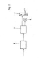
- FIG. 1 shows a section of the control table 1 of the central remote control station for the color zone adjustment in part over a range of four color zones.
- the connection of the light points of all activated light-emitting diodes 3 marks the color profile 7 across the width of the control table 1 as a qualitative rough statement about the actual existing color scheme.
- the color profile 7 is marked from left to right by the eighth, eleventh, tenth and sixth LEDs 3. The color profile in the section shown is thus sufficiently determined.
- the manipulated variable to be measured is by means of an encoder 8, z. B. a commonly used potentiometer, directly detected and supplied by this a downstream signal converter 9, in this case an analog-digital converter, as an analog input signal.
- the Sig nalwandler 9 converts the analog value of the input signal into a corresponding digital value that can be used for display.
- a rough display and a fine display go off parallel to one another.
- the converted display signal is fed to the rough display alone or additionally to the fine display, both of which have a different degree of resolution.
- this display signal becomes visible in the rough display by activating a light-emitting diode 3.
- the simultaneous lighting up of one light emitting diode of 3 different zones results in an analog representation for the color profile.
- this signal provides rough information.
- the activated light-emitting diode 3 does not provide any information about the intermediate values of the signal within the response thresholds of a light-emitting diode 3.
- the additional fine display is used to display these intermediate values in addition to the rough information.
- the value of the display signal which exceeds the lower response threshold of a light-emitting diode 3 is fed to the numerical display 6 and brought to fine display in digital digits.
- the degree of resolution of this digital fine display is considerably greater than that of the rough analog display for the color profile.
- the LED 3 remains activated in accordance with the retracted position of the actuator; the associated numerical display lights up. So z. B. the numerical display in the third numerical display 6 from the left that the actuator for the assigned color zone at deci painterly division by the value 0.2 beyond the numerical value assigned to the tenth light-emitting diode 3 is also open for coloring.
- the number zero in the first numerical display 6 means that the signal value for the lower response threshold of the sixth LED 3 is present here.
- the numerical display As a rule, a single decimal place on the numerical display is sufficient. The accuracy achieved with this corresponds at most to color quality requirements for the printed product.
- another digital, optically operating signal transmitter 6 can also be provided, the number of the transmitted pulses, e.g. B. flashes of light, a measure of the intermediate value of the display signal not yet detected by the light emitting diode 3.
- a simplification for carrying out the display method results in a particularly advantageous manner in that the light-emitting diodes 3 which are already available for the rough display of the color profile 7 are simultaneously used for the fine display, so that an additional display is completely unnecessary.
- sixteen individual light-emitting diodes 3 arranged one above the other are combined to form a vertical row of light-emitting diodes 2.
- the display is carried out in such a way that the light-emitting diode 3 activated for the analog rough display of the color profile 7 glows continuously with the same intensity, while a further light-emitting diode 3 of the same light-emitting diode row 2 with a different order number 4 by flashing in a pulsed manner or by weaker glowing, d.
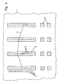
- a second exemplary embodiment of the display device shown in FIG. 4 shows the same structure as that described in FIG. 3, the rough analog display of the color profile 7 likewise taking place in the same way.
- the main difference of this second exemplary embodiment from the first is that the degree of resolution of the digital fine display has been doubled by the possibility of activating either one or two successive light-emitting diodes 3 of a row of light-emitting diodes 2.
- the simultaneous flashing of two successive light-emitting diodes 3 additionally signals an intermediate value lying in the middle between the two flashing light-emitting diodes 3.
- a constant lighting up of the eleventh LED 3 and a simultaneous pulse-like flashing of the seventh and eighth LED 3 in the second row of LEDs 2 from the left of FIG. 4 means that the actuator assigned to this color zone by the value 15/32 of the range from LED 3 to LED 3 is open beyond the lower response value of the eighth LED 3.
- a display with such a high degree of resolution also meets the highest quality requirements for the color quality of the printed product.
Landscapes
- General Physics & Mathematics (AREA)
- Physics & Mathematics (AREA)
- Inking, Control Or Cleaning Of Printing Machines (AREA)
- Indicating Measured Values (AREA)
- Electrophonic Musical Instruments (AREA)
- Water Treatment By Sorption (AREA)
- Incineration Of Waste (AREA)
- Processing Of Solid Wastes (AREA)
- External Artificial Organs (AREA)
- Electrical Discharge Machining, Electrochemical Machining, And Combined Machining (AREA)
- Financial Or Insurance-Related Operations Such As Payment And Settlement (AREA)
- Measuring And Recording Apparatus For Diagnosis (AREA)
- User Interface Of Digital Computer (AREA)
- Control Of Indicators Other Than Cathode Ray Tubes (AREA)
- Pens And Brushes (AREA)
- Selective Calling Equipment (AREA)
- Oscillators With Electromechanical Resonators (AREA)
- Apparatus For Radiation Diagnosis (AREA)
- Management, Administration, Business Operations System, And Electronic Commerce (AREA)
Priority Applications (1)
| Application Number | Priority Date | Filing Date | Title |
|---|---|---|---|
| AT79101890T ATE2494T1 (de) | 1978-07-08 | 1979-06-11 | Verfahren zum anzeigen von stellgroessen zum steuern einer rotationsdruckmaschine. |
Applications Claiming Priority (2)
| Application Number | Priority Date | Filing Date | Title |
|---|---|---|---|
| DE2830085A DE2830085C3 (de) | 1978-07-08 | 1978-07-08 | Verfahren und Vorrichtung zum Anzeigen von Stellgrößen |
| DE2830085 | 1978-07-08 |
Publications (2)
| Publication Number | Publication Date |
|---|---|
| EP0007009A1 true EP0007009A1 (fr) | 1980-01-23 |
| EP0007009B1 EP0007009B1 (fr) | 1983-02-16 |
Family
ID=6043888
Family Applications (1)
| Application Number | Title | Priority Date | Filing Date |
|---|---|---|---|
| EP79101890A Expired EP0007009B1 (fr) | 1978-07-08 | 1979-06-11 | Procédé d'affichage de grandeurs de réglage pour la commande d'une machine à imprimer à cylindres rotatifs |
Country Status (13)
| Country | Link |
|---|---|
| US (1) | US4903596A (fr) |
| EP (1) | EP0007009B1 (fr) |
| JP (2) | JPS5512495A (fr) |
| AT (1) | ATE2494T1 (fr) |
| AU (1) | AU527495B2 (fr) |
| BR (1) | BR7904306A (fr) |
| CA (1) | CA1148284A (fr) |
| DE (1) | DE2830085C3 (fr) |
| DK (1) | DK146380C (fr) |
| ES (2) | ES482202A1 (fr) |
| MX (1) | MX153236A (fr) |
| NO (1) | NO151852C (fr) |
| ZA (1) | ZA793044B (fr) |
Cited By (2)
| Publication number | Priority date | Publication date | Assignee | Title |
|---|---|---|---|---|
| EP0095649B1 (fr) * | 1982-05-29 | 1987-08-12 | Heidelberger Druckmaschinen Aktiengesellschaft | Dispositif pour commander l'alimentation en encre d'une machine à imprimer |
| EP0243697A3 (fr) * | 1986-04-30 | 1989-05-10 | Heidelberger Druckmaschinen Aktiengesellschaft | Procédé d'ajustement de dispositifs de reglage des machines d'impression |
Families Citing this family (11)
| Publication number | Priority date | Publication date | Assignee | Title |
|---|---|---|---|---|
| JPS57158953A (en) * | 1981-03-25 | 1982-09-30 | Yuasa Battery Co Ltd | Paste type plate for storage battery |
| DE3112189A1 (de) * | 1981-03-27 | 1982-10-14 | Heidelberger Druckmaschinen Ag, 6900 Heidelberg | Druckmaschine mit stellmotoren |
| DE3147312A1 (de) * | 1981-11-28 | 1983-06-09 | Heidelberger Druckmaschinen Ag, 6900 Heidelberg | Einstellvorrichtung fuer eine druckmaschine |
| US4607571A (en) * | 1982-12-21 | 1986-08-26 | Dai Nippon Insatsu Kabushiki Kaisha | Method for adjusting an ink fountain in a printing press and ink fountains |
| JPS63120653A (ja) * | 1986-11-10 | 1988-05-25 | Kinnosuke Ota | 版面自動ゴミ除去装置付き印刷機 |
| JPS6390120U (fr) * | 1986-12-03 | 1988-06-11 | ||
| JPS63230343A (ja) * | 1987-03-19 | 1988-09-26 | Toshiba Seiki Kk | 印刷機のインク供給量調整装置 |
| US5832830A (en) * | 1995-01-10 | 1998-11-10 | Heidelberger Druckmaschinen Ag | Method and apparatus for normalizing the display of ink key zero points in an ink fountain |
| JP3062167B2 (ja) * | 1998-11-20 | 2000-07-10 | 株式会社東京機械製作所 | 刷版装着位置指示装置 |
| JP4847113B2 (ja) * | 2005-11-30 | 2011-12-28 | 柳井紙工株式会社 | 組立て紙箱 |
| JP2008037046A (ja) * | 2006-08-09 | 2008-02-21 | Mitsubishi Heavy Ind Ltd | 印刷機の操作デスク |
Citations (9)
| Publication number | Priority date | Publication date | Assignee | Title |
|---|---|---|---|---|
| DE1623873A1 (de) * | 1967-06-02 | 1970-10-29 | Vdo Schindling | Vorrichtung zur Anzeige von Messwerten |
| FR2067650A5 (fr) * | 1969-11-12 | 1971-08-20 | Marinoni | |
| DE2141355A1 (de) * | 1970-08-19 | 1972-02-24 | Strachan & Henshaw Ltd | Einstellmechanismus für Druckfarben-Versorgungseinrichtung sowie Druckfarben-Versorgungseinrichtung mit solchem Einstellmechanismus |
| FR2214130A1 (fr) * | 1973-01-17 | 1974-08-09 | Sintra | |
| US3930447A (en) * | 1974-07-22 | 1976-01-06 | Harris Corporation | Dual purpose display for printing presses |
| US3990799A (en) * | 1974-01-14 | 1976-11-09 | Minolta Camera Kabushiki Kaisha | Digital exposure meter |
| US4008664A (en) * | 1973-07-23 | 1977-02-22 | Harris-Intertype Corporation | Ink key control system |
| US4014011A (en) * | 1975-04-25 | 1977-03-22 | Hewlett-Packard Company | Variable resolution display |
| BE868221A (fr) * | 1977-06-18 | 1978-10-16 | Heidelberger Druckmasch Ag | Dispositif pour commander la conduite de l'encrage dans les presses d'imprimerie rotatives |
Family Cites Families (17)
| Publication number | Priority date | Publication date | Assignee | Title |
|---|---|---|---|---|
| DD85081A (fr) * | ||||
| DE7228918U (de) * | 1973-10-04 | Maschinenfabrik Augsburg Nuernberg Ag | Einrichtung an Farbwerken von Druckmaschinen | |
| FR85705E (fr) * | 1964-01-22 | 1965-10-01 | Electronique Et D Automatique | Procédé de contrôle de la position relative d'une pièce fixe et d'un organe rotatif |
| US3644784A (en) * | 1970-04-16 | 1972-02-22 | Honeywell Inc | Solid-state indicator displays |
| US3689835A (en) * | 1970-09-10 | 1972-09-05 | Veeder Industries Inc | Analog/digital meter having front indicator means overlying a rear indicator means |
| US3726250A (en) * | 1971-03-18 | 1973-04-10 | Marconi Co Canada | Indicator |
| JPS542116B1 (fr) * | 1971-06-26 | 1979-02-02 | ||
| US3772874A (en) * | 1971-12-09 | 1973-11-20 | Princeton Materials Science | Display apparatus and chronometer utilizing optically variable liquid |
| US3771015A (en) * | 1972-02-09 | 1973-11-06 | Beckman Instruments Inc | Light-emitting diode display |
| US3825827A (en) * | 1972-04-13 | 1974-07-23 | Bendix Corp | Columnar display for electrical signals with digital signal limit set |
| JPS5121370B2 (fr) * | 1972-05-26 | 1976-07-02 | ||
| DE2331660B2 (de) * | 1973-06-22 | 1977-02-03 | Robert Bosch Gmbh, 7000 Stuttgart | Schaltungsanordnung zur anzeige einer gleichspannung mittels elektro- optischer anzeigeelemente |
| US3925770A (en) * | 1974-07-29 | 1975-12-09 | Business Electronics Inc | Audible signaling device for a computer |
| JPS5121370U (fr) * | 1974-08-03 | 1976-02-17 | ||
| DE2514167B2 (de) * | 1975-03-29 | 1977-04-28 | Schenk, Christoph, Dipl.-Phys., 8551 Adelsdorf | Ansteuerschaltung fuer quasi-analoge leuchtbandanzeige |
| US4155084A (en) * | 1977-09-08 | 1979-05-15 | The United States Of America As Represented By The Secretary Of The Navy | Solid state LED display device |
| DE2744946A1 (de) * | 1977-10-06 | 1979-04-19 | Hartmann & Braun Ag | Anordnung zur anzeige von messwerten |
-
1978
- 1978-07-08 DE DE2830085A patent/DE2830085C3/de not_active Expired
-
1979
- 1979-06-11 EP EP79101890A patent/EP0007009B1/fr not_active Expired
- 1979-06-11 AT AT79101890T patent/ATE2494T1/de not_active IP Right Cessation
- 1979-06-19 ZA ZA793044A patent/ZA793044B/xx unknown
- 1979-06-29 NO NO792192A patent/NO151852C/no unknown
- 1979-07-04 ES ES482202A patent/ES482202A1/es not_active Expired
- 1979-07-05 DK DK285179A patent/DK146380C/da active
- 1979-07-06 BR BR7904306A patent/BR7904306A/pt not_active IP Right Cessation
- 1979-07-06 CA CA000331347A patent/CA1148284A/fr not_active Expired
- 1979-07-09 AU AU48790/79A patent/AU527495B2/en not_active Ceased
- 1979-07-09 JP JP8600979A patent/JPS5512495A/ja active Pending
- 1979-07-09 MX MX178396A patent/MX153236A/es unknown
-
1980
- 1980-04-15 ES ES490579A patent/ES8100970A1/es not_active Expired
-
1983
- 1983-04-22 JP JP1983059528U patent/JPS594424U/ja active Granted
-
1987
- 1987-09-14 US US07/096,595 patent/US4903596A/en not_active Expired - Lifetime
Patent Citations (11)
| Publication number | Priority date | Publication date | Assignee | Title |
|---|---|---|---|---|
| DE1623873A1 (de) * | 1967-06-02 | 1970-10-29 | Vdo Schindling | Vorrichtung zur Anzeige von Messwerten |
| FR2067650A5 (fr) * | 1969-11-12 | 1971-08-20 | Marinoni | |
| DE2141355A1 (de) * | 1970-08-19 | 1972-02-24 | Strachan & Henshaw Ltd | Einstellmechanismus für Druckfarben-Versorgungseinrichtung sowie Druckfarben-Versorgungseinrichtung mit solchem Einstellmechanismus |
| FR2214130A1 (fr) * | 1973-01-17 | 1974-08-09 | Sintra | |
| US4008664A (en) * | 1973-07-23 | 1977-02-22 | Harris-Intertype Corporation | Ink key control system |
| US3990799A (en) * | 1974-01-14 | 1976-11-09 | Minolta Camera Kabushiki Kaisha | Digital exposure meter |
| US3930447A (en) * | 1974-07-22 | 1976-01-06 | Harris Corporation | Dual purpose display for printing presses |
| US4014011A (en) * | 1975-04-25 | 1977-03-22 | Hewlett-Packard Company | Variable resolution display |
| BE868221A (fr) * | 1977-06-18 | 1978-10-16 | Heidelberger Druckmasch Ag | Dispositif pour commander la conduite de l'encrage dans les presses d'imprimerie rotatives |
| NL7806524A (nl) * | 1977-06-18 | 1978-12-20 | Heidelberger Druckmasch Ag | Inrichting voor het besturen van de inktgeleiding aan rotatiedrukmachines. |
| FR2394398A1 (fr) * | 1977-06-18 | 1979-01-12 | Heidelberger Druckmasch Ag | Installation de commande de l'amenee d'encre dans des machines a imprimer rotatives |
Cited By (2)
| Publication number | Priority date | Publication date | Assignee | Title |
|---|---|---|---|---|
| EP0095649B1 (fr) * | 1982-05-29 | 1987-08-12 | Heidelberger Druckmaschinen Aktiengesellschaft | Dispositif pour commander l'alimentation en encre d'une machine à imprimer |
| EP0243697A3 (fr) * | 1986-04-30 | 1989-05-10 | Heidelberger Druckmaschinen Aktiengesellschaft | Procédé d'ajustement de dispositifs de reglage des machines d'impression |
Also Published As
| Publication number | Publication date |
|---|---|
| DK285179A (da) | 1980-01-09 |
| ATE2494T1 (de) | 1983-03-15 |
| EP0007009B1 (fr) | 1983-02-16 |
| JPH0114885Y2 (fr) | 1989-05-02 |
| ES490579A0 (es) | 1980-12-01 |
| NO151852C (no) | 1985-06-19 |
| AU527495B2 (en) | 1983-03-10 |
| DK146380C (da) | 1984-03-05 |
| AU4879079A (en) | 1980-01-17 |
| ZA793044B (en) | 1980-07-30 |
| DE2830085A1 (de) | 1980-01-17 |
| ES8100970A1 (es) | 1980-12-01 |
| DK146380B (da) | 1983-09-26 |
| ES482202A1 (es) | 1980-07-01 |
| JPS594424U (ja) | 1984-01-12 |
| CA1148284A (fr) | 1983-06-14 |
| NO151852B (no) | 1985-03-11 |
| DE2830085C3 (de) | 1986-07-10 |
| US4903596A (en) | 1990-02-27 |
| JPS5512495A (en) | 1980-01-29 |
| MX153236A (es) | 1986-09-02 |
| DE2830085B2 (de) | 1980-07-17 |
| NO792192L (no) | 1980-03-24 |
| BR7904306A (pt) | 1980-04-01 |
Similar Documents
| Publication | Publication Date | Title |
|---|---|---|
| EP0095649B1 (fr) | Dispositif pour commander l'alimentation en encre d'une machine à imprimer | |
| DE3633855C2 (fr) | ||
| EP0007009A1 (fr) | Procédé d'affichage de grandeurs de réglage pour la commande d'une machine à imprimer à cylindres rotatifs | |
| EP0356705B1 (fr) | Lecture de données pour un dispositif de réglage de l'encre | |
| DE2727426A1 (de) | Vorrichtung zum steuern der farbfuehrung an rotationsdruckmaschinen | |
| DE2947791A1 (de) | Einrichtung zur farbueberwachung von bogen- oder bahnfoermigen, in bewegung befindlichen materialien, insbesondere der druckmaterialien von druckmaterialien von druckmaschinen | |
| CH667617A5 (de) | Steuervorrichtung fuer einen stellantrieb an einer druckmaschine. | |
| EP0860276B1 (fr) | Procédé et dispositif de contrôle de qualité | |
| EP0123257A2 (fr) | Procédé et dispositif de réglage de l'alimentation en encre des encriers d'une machine à imprimer en plusieurs couleurs | |
| DE3942254C2 (fr) | ||
| DE2449287A1 (de) | Metrologisches geraet | |
| DE3024452A1 (de) | Einrichtung zur anzeige der elektrisch erfassbaren stellungen bzw. einstellungen einzelner fuer den druckprozess benoetigten einrichtungen | |
| DE3334019A1 (de) | Verfahren und vorrichtung zur einstellung der den farbzonen eines farbwerks zugeordneten dosierorgane | |
| DE2164351C2 (de) | Anzeigeeinrichtung für die Stellung der Zonenschrauben des Farbmessers eines Farbkastens einer Druckmaschine | |
| DE1671439A1 (de) | Anordnung zur Messung der Stromstaerke an den einzelnen Elektroden von Elektrolysezellen | |
| DE2238007A1 (de) | Geraet zur kontrolle der konstanz der farbgebung von druckbogen | |
| EP0136520B1 (fr) | Dispositif pour l'enregistrement de valeurs densitométriques d'une bande de contrôle | |
| DE2301393A1 (de) | Verfahren und vorrichtung zum analysieren einer vorlage zur festlegung von rastertonwerten fuer die reproduktion anhand der druckkennlinien einer druckfarbenskala od.dgl | |
| DE729673C (de) | Einrichtung zum Feststellen der relativen Lage der Bilder oder Druckmarken von Papier- oder Stoffbahnen | |
| DE3328810C2 (fr) | ||
| DE3030266A1 (de) | Analog registrierender ein- oder mehrkanalschreiber mit (alpha)numerischer druckeinrichtung | |
| DE3102377A1 (de) | Farbwerkfernverstellsystem | |
| EP0642012A1 (fr) | Dispositif et procédé pour des mesures densitométriques et/ou colorimétriques | |
| DE2357317C3 (de) | Einrichtung zum Anbringen von Kontrollziffern laufender oder springender Folge auf Gegenständen mit bedruckbarer Oberflache oder auf perforierbaren Gegenständen | |
| CH632852A5 (de) | Kontrolleinrichtung zur densitometrischen auswertung von druckbogen mit aufgedrucktem druck-kontrollstreifen. |
Legal Events
| Date | Code | Title | Description |
|---|---|---|---|
| PUAI | Public reference made under article 153(3) epc to a published international application that has entered the european phase |
Free format text: ORIGINAL CODE: 0009012 |
|
| AK | Designated contracting states |
Designated state(s): AT BE CH FR GB IT NL SE |
|
| 17P | Request for examination filed | ||
| ITF | It: translation for a ep patent filed | ||
| GRAA | (expected) grant |
Free format text: ORIGINAL CODE: 0009210 |
|
| AK | Designated contracting states |
Designated state(s): AT BE CH FR GB IT NL SE |
|
| REF | Corresponds to: |
Ref document number: 2494 Country of ref document: AT Date of ref document: 19830315 Kind code of ref document: T |
|
| ET | Fr: translation filed | ||
| PLBI | Opposition filed |
Free format text: ORIGINAL CODE: 0009260 |
|
| 26 | Opposition filed |
Opponent name: M.A.N.- ROLAND DRUCKMASCHINEN AKTIENGESELLSCHAFT Effective date: 19831105 |
|
| PLBI | Opposition filed |
Free format text: ORIGINAL CODE: 0009260 |
|
| 26 | Opposition filed |
Opponent name: KOENIG & BAUER AKTIENGESELLSCHAFT Effective date: 19831117 |
|
| PLBN | Opposition rejected |
Free format text: ORIGINAL CODE: 0009273 |
|
| STAA | Information on the status of an ep patent application or granted ep patent |
Free format text: STATUS: OPPOSITION REJECTED |
|
| 27O | Opposition rejected |
Effective date: 19860422 |
|
| NLR2 | Nl: decision of opposition | ||
| ITTA | It: last paid annual fee | ||
| PGFP | Annual fee paid to national office [announced via postgrant information from national office to epo] |
Ref country code: AT Payment date: 19920604 Year of fee payment: 14 |
|
| PGFP | Annual fee paid to national office [announced via postgrant information from national office to epo] |
Ref country code: SE Payment date: 19920615 Year of fee payment: 14 |
|
| PGFP | Annual fee paid to national office [announced via postgrant information from national office to epo] |
Ref country code: NL Payment date: 19920630 Year of fee payment: 14 |
|
| PG25 | Lapsed in a contracting state [announced via postgrant information from national office to epo] |
Ref country code: AT Effective date: 19930611 |
|
| PG25 | Lapsed in a contracting state [announced via postgrant information from national office to epo] |
Ref country code: SE Effective date: 19930612 |
|
| PG25 | Lapsed in a contracting state [announced via postgrant information from national office to epo] |
Ref country code: NL Effective date: 19940101 |
|
| NLV4 | Nl: lapsed or anulled due to non-payment of the annual fee | ||
| EUG | Se: european patent has lapsed |
Ref document number: 79101890.6 Effective date: 19940110 |
|
| PGFP | Annual fee paid to national office [announced via postgrant information from national office to epo] |
Ref country code: FR Payment date: 19950602 Year of fee payment: 17 |
|
| PGFP | Annual fee paid to national office [announced via postgrant information from national office to epo] |
Ref country code: BE Payment date: 19950608 Year of fee payment: 17 |
|
| PGFP | Annual fee paid to national office [announced via postgrant information from national office to epo] |
Ref country code: CH Payment date: 19950808 Year of fee payment: 17 |
|
| PGFP | Annual fee paid to national office [announced via postgrant information from national office to epo] |
Ref country code: GB Payment date: 19960520 Year of fee payment: 18 |
|
| PG25 | Lapsed in a contracting state [announced via postgrant information from national office to epo] |
Ref country code: CH Effective date: 19960630 Ref country code: BE Effective date: 19960630 |
|
| BERE | Be: lapsed |
Owner name: HEIDELBERGER DRUCKMASCHINEN A.G. Effective date: 19960630 |
|
| REG | Reference to a national code |
Ref country code: CH Ref legal event code: PL |
|
| PG25 | Lapsed in a contracting state [announced via postgrant information from national office to epo] |
Ref country code: FR Effective date: 19970228 |
|
| REG | Reference to a national code |
Ref country code: FR Ref legal event code: ST |
|
| PG25 | Lapsed in a contracting state [announced via postgrant information from national office to epo] |
Ref country code: GB Free format text: LAPSE BECAUSE OF NON-PAYMENT OF DUE FEES Effective date: 19970611 |
|
| GBPC | Gb: european patent ceased through non-payment of renewal fee |
Effective date: 19970611 |