EP0007139A2 - Condensateur multiple équipé de dispositifs de refroidissement et son procédé de fabrication - Google Patents
Condensateur multiple équipé de dispositifs de refroidissement et son procédé de fabrication Download PDFInfo
- Publication number
- EP0007139A2 EP0007139A2 EP79200372A EP79200372A EP0007139A2 EP 0007139 A2 EP0007139 A2 EP 0007139A2 EP 79200372 A EP79200372 A EP 79200372A EP 79200372 A EP79200372 A EP 79200372A EP 0007139 A2 EP0007139 A2 EP 0007139A2
- Authority
- EP
- European Patent Office
- Prior art keywords
- rollers
- capacitor
- bent
- ribbon
- hand
- Prior art date
- Legal status (The legal status is an assumption and is not a legal conclusion. Google has not performed a legal analysis and makes no representation as to the accuracy of the status listed.)
- Granted
Links
Images

Classifications
-
- H—ELECTRICITY
- H01—ELECTRIC ELEMENTS
- H01G—CAPACITORS; CAPACITORS, RECTIFIERS, DETECTORS, SWITCHING DEVICES, LIGHT-SENSITIVE OR TEMPERATURE-SENSITIVE DEVICES OF THE ELECTROLYTIC TYPE
- H01G2/00—Details of capacitors not covered by a single one of groups H01G4/00-H01G11/00
- H01G2/08—Cooling arrangements; Heating arrangements; Ventilating arrangements
-
- H—ELECTRICITY
- H01—ELECTRIC ELEMENTS
- H01G—CAPACITORS; CAPACITORS, RECTIFIERS, DETECTORS, SWITCHING DEVICES, LIGHT-SENSITIVE OR TEMPERATURE-SENSITIVE DEVICES OF THE ELECTROLYTIC TYPE
- H01G4/00—Fixed capacitors; Processes of their manufacture
- H01G4/38—Multiple capacitors, i.e. structural combinations of fixed capacitors
-
- Y—GENERAL TAGGING OF NEW TECHNOLOGICAL DEVELOPMENTS; GENERAL TAGGING OF CROSS-SECTIONAL TECHNOLOGIES SPANNING OVER SEVERAL SECTIONS OF THE IPC; TECHNICAL SUBJECTS COVERED BY FORMER USPC CROSS-REFERENCE ART COLLECTIONS [XRACs] AND DIGESTS
- Y10—TECHNICAL SUBJECTS COVERED BY FORMER USPC
- Y10T—TECHNICAL SUBJECTS COVERED BY FORMER US CLASSIFICATION
- Y10T29/00—Metal working
- Y10T29/43—Electric condenser making
- Y10T29/435—Solid dielectric type
Definitions
- the subject of the present invention is power capacitors, in particular, but not exclusively, capacitors for low voltage, composed of rolls of capacitors with armatures connected to external terminals, housed in a metal case and comprising heat conducting sheets placed in contact on the one hand with the rollers and on the other hand with the metal case.
- capacitors are known per se, but require complicated or expensive arrangements such as the coating of the rollers in metal sheaths or housings or springs which ensure a certain contact pressure between the heat conducting sheets and the walls of the metal case. on the one hand and capacitor rollers on the other.
- the object of the invention is to ensure an efficient evacuation of the heat produced in the condenser rolls by means of heat conducting sheets of very simple shape, the introduction of which into metal housings, far from complicating the manufacturing process. , rather facilitates nanipulations and allows a faster assembly speed than that for capacitors not provided with heat conducting sheets.
- the capacitor according to the invention is characterized in that the heat conducting sheets are tapes made of an elastic metal, a good heat conductor, of width approximately equal to the height of a roll of condenser, in that these tapes are bent so as to each fit at least half the periphery of each of several capacitor rollers, and in that the two non-curved ends of each strip are arranged in intimate contact with two opposite walls of the metal case.
- the subject of the invention is also a method of manufacturing such capacitors, characterized in that tapes of heat conducting sheet are conformed so that they have one or more parts of curved cylindrical surfaces, which are clamped in the concave parts of the ribbon of the condenser rollers, which are compressed by the ribbon and condenser roller assembly and inserted between two opposite walls of the metal casing so that the bent ribbon remains compressed and is elastically pushed into close contact from 68.09 1771 part on about half of the surface of each roll and on the other hand on two opposite walls of the metal case.
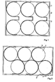
- Figures 1,2,3 of the drawing are sections through capacitors composed of one or more capacitor rollers.
- Figure 4 is a similar section of a set of rollers perpendicular to the axes of the rollers, before mounting in a housing.
- Figure 1 is shown in section a capacitor composed of six rollers 1 of capacitor, housed in a housing 2.
- the armatures, not shown, of the rollers 1 are connected to external terminals, not shown.
- Each roll of capacitor 1 is in intimate contact with a sheet of heat conducting sheet 3 of width equal approximately to the height of the roll 1.
- the tapes 3 are bent so as to each fit approximately half the circumference of each of two rollers 1
- the non-curved ends of each strip 3 are placed in intimate contact with two opposite walls of the metal case 2. This intimate contact does not exclude a thin layer of electrical insulation between the ends of the strips 3 and the walls of the case 2.
- the sheet metal strips 3 are shaped so that they have two parts of curved cylindrical surfaces.
- the heat is dissipated by the tapes 3 towards the walls of the housing 2, even if the interstices between the rollers are filled with a heat-insulating substance such as for example vermiculite powder and even if a thin layer of electrical insulation is interposed between the tapes and the walls of the housing 2.
- a heat-insulating substance such as for example vermiculite powder
- the ribbons 3 can be of any metal having sufficient elasticity and a coefficient of heat conductivity, for example copper, aluminum, steel etc. Due to its very low specific weight and excellent heat conductivity, aluminum is particularly well suited. Aluminum tapes have sufficient elasticity and are not subject to corrosion. The gaps between the rollers can be filled in particular with vermiculite powder.
- ribbons 4 are bent, not in double C as in Figure 1, but in S and hugging only a little more than half the perimeter of each roll.
- ribbons 6 in double S are each assembled, not with 2, but with 3 rollers 1 and inserted in packs of three rollers 1 in the housing 2.
- the method of manufacturing capacitors as described above is particularly advantageous when the opposite walls of a metal case 2 are spaced from each other by less than a span or by 20 cm, so that the assemblies of bent tapes and rollers can be gripped and compressed with one hand and inserted into the housing.
Landscapes
- Engineering & Computer Science (AREA)
- Power Engineering (AREA)
- Microelectronics & Electronic Packaging (AREA)
- Manufacturing & Machinery (AREA)
- Fixed Capacitors And Capacitor Manufacturing Machines (AREA)
- Devices That Are Associated With Refrigeration Equipment (AREA)
- Transformers For Measuring Instruments (AREA)
- Mounting Components In General For Electric Apparatus (AREA)
- Electric Double-Layer Capacitors Or The Like (AREA)
Abstract
Description
- La présente invention a pour objet des condensateurs de puissance, notamment, mais non exclusivement, des condensateurs pour basse tension, composés de rouleaux de condensateurs à armatures reliées à des bornes extérieures, logés dans un boîtier métallique et comprenant des tôles conductrices de chaleur mis en contact d'une part avec les rouleaux et d'autre part avec le boîtier métallique. De tels condensateurs sont en soi connus, mais nécessitent des aménagements compliqués ou coûteux tel que l'enrobage des rouleaux dans des gaines ou boîtiers métalliques ou des ressorts qui assurent une certaine pression de contact entre les tôles conductrices de chaleur et les parois du boîtier métallique d'une part et des rouleaux de condensateur d'autre part.
- Le but de l'invention est d'assurer une évacuation efficace de la chaleur produite dans les rouleaux de condensateur au moyen de tôles conductrices de la chaleur de forme très simple dont l'introduction dans les boîtiers métalliques, loin de compliquer le procédé de fabrication, facilite plutôt les nanipulations et permet d'atteindre une rapidité de montage plus grande que celle pour des condensateurs non munis de tôles conductrices de chaleur.
- Le condensateur suivant l'invention est caractèrisé en ce que les tôles conductrices de chaleur sont des rubans en un métal élastique, bon conducteur de chaleur, de largeur égale environ à la hauteur d'un rouleau de condensateur,en ce que ces rubans sont cintrés de manière à épouser chacun au moins la moitié du pourtour de chacun de plusieurs rouleaux de condensateur, et en ce que les deux extrémités non cintrées de chaque ruban sont disposées en contact intime avec deux parois opposées du boîtier métallique.
- L'invention a pour objet aussi un procédé de fabrication de tels condensateurs, caractérisé en ce qu'on conforme des rubans de tôle conductrice de chaleur de manière qu'ils présentent une ou plusieurs parties de surfaces cylindriques cintrées, qu'on pince dans les parties concaves du ruban des rouleaux de condensateur, qu'on comprime l'assemblage ruban et rouleaux de condensateur et qu'on l'insère entre deux parois opposées du boîtier métallique de manière que le ruban cintré reste comprimé et est poussé élastiquement en contact étroit d'une 68.09 1771 part sur environ la moitié de la surface de chaque rouleau et d'autre part sur deux parois opposées du boîtier métallique.
- L'invention est expliquée ci-dessous par rapport à quelques exemples de forme d'exécution représentés au dessin annexé. Les figures 1,2, 3, du dessin sont des coupes à travers des condensateurs composés de un ou de plusieurs rouleaux de condensateur. La figure 4 est une coupe analogue d'un ensemble de rouleaux perpendiculaire aux axes des rouleaux, avant le montage dans un boîtier.
- A la figure 1 est montré en coupe un condensateur composé de six rouleaux 1 de condensateur, logé dans un boîtier 2. Les armatures, non représentées, des rouleaux 1 sont reliées à des bornes extérieures, non représentées. Chaque rouleau de condensateur 1 est en contact intime avec un ruban de tôle 3 conductrice de chaleur de largeur égale environ à la hauteur du rouleau 1. Les rubans 3 sont cintrés de manière à épouser chacun environ la moitié du pourtour de chacun de deux rouleaux 1. Les extrémités non cintrées de chaque ruban 3 sont disposés en contact intime avec deux parois opposées du boîtier métallique 2. Ce contact intime n'exclut pas une fine couche d'isolant électrique entre les extrémités des rubans 3 et les parois du boîtier 2. Lors de la fabrication du condensateur suivant la figure 1, les rubans de tôle 3 sont conformés de manière à ce qu'ils présentent deux parties de surfaces cylindriques cintrées. Dans les parties concaves du ruban cintré, on retient par pinçage des rouleaux de condensateur 1. Lors du montage, on assemble avec chaque ruban cintré 3 deux rouleaux 1, on comprime l'assemblage rouleaux 1 et ruban 3 dans la direction qui rapproche l'un de l'autre les extrémités non cintrées du ruban 3 et on insère l'assemblage comprimé entre deux parois opposées du boîtier 2. De cette manière le ruban 3 reste comprimé entre les deux parois et est poussé êlasti- quement en contact étroit d'une part sur environ la moitié de la surface de chaque rouleau et d'autre part sur deux parois opposées du boîtier métallique. Grâce à la pression de contact exercée par l'élasticité des rubans 3 comprimés, la chaleur s'évacue par les rubans 3 vers les parois du boîtier 2, même si les interstices entre les rouleaux sont remplis d'une substance calorifuge telle par exemple de la poudre de vermiculite et même si une mince couche d'isolant électrique est interposée entre les rubans et les parois du boîtier 2. 68.09/1771
- Les rubans 3 peuvent être en n'importe quel métal possédant une élasticité et un coefficient de conductibilité calorifique suffisants, par exemple en cuivre, aluminium, acier etc. En raison de son poids spécifique très faible et de sa conductibilité calorifique excellente, l'aluminium est particulièrement bien adapté. Des rubans en aluminium présentent une élasticité suffisante et ne sont pas soumis à la corrosion. Les interstices entre les rouleaux peuvent être remplies notamment par de la poudre de vermiculite.
- Dans une autre solution montrée à la figure 2 des rubans 4 sont cintrés, non en double C comme à la figure 1, mais en S et épousant seulement un peu plus que la moitié du pourtour de chaque rouleau.
- Dans une solution montrée à la figure 3, des rubans 6 en double S sont assemblés chacun, non avec 2, mais avec 3 rouleaux 1 et insérés par paquets de trois rouleaux 1 dans le boîtier 2.
- Il est à remarquer que le procédé de fabrication de condensateurs comme décrit ci-dessus est particulièrement avantageux lorsque les parois opposées d'un boîtier métallique 2 sont distants l'un de l'autre de moins d'un empan ou de 20 cm, de manière que les assemblagesde rubans cintrés et rouleaux peuvent être saisis et comprimés à une seule main et insérés dans le boîtier.
- Il est également avantageux, notamment dans le cas de rubans pliés en double C d'assembler au préalable tous les rouleaux qui doivent être introduits dans un boitier au moyen d'un pinçage dans les parties concaves des rubans pliés e.t double C et par un assemblage au moyen d'un tirant 8 tel que montré à la figure 4.
- Dans le cas d'un assemblage selon les figures 1 à.3 il est possible de préassembler le tout en l'entourant d'un tour de bande adhésive, isolante électrique.
Claims (7)
Priority Applications (1)
| Application Number | Priority Date | Filing Date | Title |
|---|---|---|---|
| AT79200372T ATE662T1 (de) | 1978-07-18 | 1979-07-06 | Mit kuehlvorrichtungen versehener vielfachkondensator und verfahren zu seiner herstellung. |
Applications Claiming Priority (2)
| Application Number | Priority Date | Filing Date | Title |
|---|---|---|---|
| EP78200110 | 1978-07-18 | ||
| EP78200110 | 1978-07-18 |
Publications (3)
| Publication Number | Publication Date |
|---|---|
| EP0007139A2 true EP0007139A2 (fr) | 1980-01-23 |
| EP0007139A3 EP0007139A3 (en) | 1980-02-06 |
| EP0007139B1 EP0007139B1 (fr) | 1982-02-03 |
Family
ID=8185960
Family Applications (1)
| Application Number | Title | Priority Date | Filing Date |
|---|---|---|---|
| EP79200372A Expired EP0007139B1 (fr) | 1978-07-18 | 1979-07-06 | Condensateur multiple équipé de dispositifs de refroidissement et son procédé de fabrication |
Country Status (8)
| Country | Link |
|---|---|
| US (1) | US4309739A (fr) |
| EP (1) | EP0007139B1 (fr) |
| AT (1) | ATE662T1 (fr) |
| DE (1) | DE2962046D1 (fr) |
| DK (1) | DK147897C (fr) |
| ES (1) | ES8406782A3 (fr) |
| IN (1) | IN151450B (fr) |
| ZA (1) | ZA793572B (fr) |
Cited By (1)
| Publication number | Priority date | Publication date | Assignee | Title |
|---|---|---|---|---|
| EP0088833A1 (fr) * | 1982-03-15 | 1983-09-21 | ASEA-JUMET, Société Anonyme | Condensateur multiple équipé de dispositifs de refroidissement |
Families Citing this family (4)
| Publication number | Priority date | Publication date | Assignee | Title |
|---|---|---|---|---|
| FI118781B (fi) * | 2003-06-04 | 2008-03-14 | Vacon Oyj | Kondensaattorin kiinnitys- ja suojajärjestely |
| JP4186838B2 (ja) * | 2004-02-20 | 2008-11-26 | 株式会社デンソー | 車両用発電機 |
| BR112018074842B8 (pt) * | 2016-07-20 | 2022-12-27 | Hitachi Energy Switzerland Ag | Unidade de capacitor de potência |
| DE102021110585B4 (de) * | 2021-04-26 | 2025-11-20 | Schaeffler Technologies AG & Co. KG | Zwischenkreiskondensator mit Wärmeableitung |
Family Cites Families (10)
| Publication number | Priority date | Publication date | Assignee | Title |
|---|---|---|---|---|
| US1751939A (en) * | 1928-07-12 | 1930-03-25 | Telefunken Gmbh | Insulation of electrical apparatus |
| FR989052A (fr) * | 1949-04-20 | 1951-09-04 | Alsthom Cgee | Nouvelles dispositions améliorant le refroidissement des condensateurs électriquesstatiques |
| US2768230A (en) * | 1954-05-26 | 1956-10-23 | Union Carbide & Carbon Corp | Battery assembly and attachment therefor |
| US3238489A (en) * | 1962-06-11 | 1966-03-01 | Dale Electronics | Electrical resistor |
| US3219892A (en) | 1962-09-18 | 1965-11-23 | Gen Electric | Electric capacitor cooling means |
| US3222448A (en) * | 1964-06-23 | 1965-12-07 | John W Rogers | Electrical component holder |
| US3254281A (en) * | 1964-10-29 | 1966-05-31 | Westinghouse Electric Corp | Power capacitor device having improved temperature operating characteristics |
| DE1269247B (de) * | 1964-12-18 | 1968-05-30 | Ero Starkstrom Kondensatoren | In ein Gehaeuse eingebauter luftgekuehlter Leistungskondensator und Verfahren zu seiner Herstellung |
| US4041524A (en) * | 1974-12-30 | 1977-08-09 | The Staver Company, Inc. | Heat dissipating device for transistor with outwardly extending heat conductive tab |
| FR2405546A1 (en) * | 1978-09-20 | 1979-05-04 | Rectiphase Mae | Non-flammable dry capacitor construction - comprises a case contg. wound synthetic foils and filled with a powdery high melting desiccant |
-
1979
- 1979-07-06 DE DE7979200372T patent/DE2962046D1/de not_active Expired
- 1979-07-06 AT AT79200372T patent/ATE662T1/de not_active IP Right Cessation
- 1979-07-06 EP EP79200372A patent/EP0007139B1/fr not_active Expired
- 1979-07-16 US US06/057,897 patent/US4309739A/en not_active Expired - Lifetime
- 1979-07-16 ZA ZA00793572A patent/ZA793572B/xx unknown
- 1979-07-17 DK DK299879A patent/DK147897C/da active
- 1979-07-18 IN IN738/CAL/79A patent/IN151450B/en unknown
-
1983
- 1983-10-20 ES ES526589A patent/ES8406782A3/es not_active Expired
Cited By (1)
| Publication number | Priority date | Publication date | Assignee | Title |
|---|---|---|---|---|
| EP0088833A1 (fr) * | 1982-03-15 | 1983-09-21 | ASEA-JUMET, Société Anonyme | Condensateur multiple équipé de dispositifs de refroidissement |
Also Published As
| Publication number | Publication date |
|---|---|
| DK147897C (da) | 1985-06-24 |
| ATE662T1 (de) | 1982-02-15 |
| ZA793572B (en) | 1980-08-27 |
| ES526589A0 (es) | 1984-08-01 |
| ES8406782A3 (es) | 1984-08-01 |
| EP0007139B1 (fr) | 1982-02-03 |
| EP0007139A3 (en) | 1980-02-06 |
| IN151450B (fr) | 1983-04-23 |
| DE2962046D1 (en) | 1982-03-11 |
| DK147897B (da) | 1985-01-02 |
| DK299879A (da) | 1980-01-19 |
| US4309739A (en) | 1982-01-05 |
Similar Documents
| Publication | Publication Date | Title |
|---|---|---|
| US4100398A (en) | Laminated electrically heatable window with electrical connectors | |
| JPH03208840A (ja) | 加熱可能な合わせガラス板及びその製造方法 | |
| JP4069513B2 (ja) | リード線および該リード線の接続された太陽電池パネル | |
| EP0007139B1 (fr) | Condensateur multiple équipé de dispositifs de refroidissement et son procédé de fabrication | |
| CN108429019A (zh) | 一种双孔径五层压接装置 | |
| US3517112A (en) | Electrical terminal connector for sodium cable | |
| US3639680A (en) | Insulated bus bar assembly | |
| US2129947A (en) | Contacting terminal structure for electrical devices | |
| CN108598719A (zh) | 一种三层压接装置 | |
| JP2898336B2 (ja) | Ptcサーミスタの製造方法 | |
| JP4028143B2 (ja) | 絶縁処理された端末部を有するフラットケーブルの製造方法 | |
| US4456945A (en) | Capacitor | |
| CN223928053U (zh) | 一种防水母线槽 | |
| CN222190954U (zh) | 电池顶盖结构、电池以及用电设备 | |
| FR2601826A1 (fr) | Bande souple de raccordement electrique | |
| CN118335390B (zh) | 一种智能电网用平滑铝高压电力电缆 | |
| JP3107128B2 (ja) | シート電線の絶縁構造および絶縁方法 | |
| JP2002151308A (ja) | 避雷装置 | |
| CN224124112U (zh) | 分支连接器 | |
| JPH0339859Y2 (fr) | ||
| BE563090A (fr) | ||
| CN2651971Y (zh) | 电源插头 | |
| BE439169A (fr) | ||
| JPH0314027Y2 (fr) | ||
| JPS6328827Y2 (fr) |
Legal Events
| Date | Code | Title | Description |
|---|---|---|---|
| PUAI | Public reference made under article 153(3) epc to a published international application that has entered the european phase |
Free format text: ORIGINAL CODE: 0009012 |
|
| PUAL | Search report despatched |
Free format text: ORIGINAL CODE: 0009013 |
|
| AK | Designated contracting states |
Designated state(s): AT BE CH DE FR GB IT LU NL SE |
|
| AK | Designated contracting states |
Designated state(s): AT BE CH DE FR GB IT LU NL SE |
|
| 17P | Request for examination filed | ||
| ITF | It: translation for a ep patent filed | ||
| GRAA | (expected) grant |
Free format text: ORIGINAL CODE: 0009210 |
|
| AK | Designated contracting states |
Designated state(s): AT BE CH DE FR GB IT LU NL SE |
|
| REF | Corresponds to: |
Ref document number: 662 Country of ref document: AT Date of ref document: 19820215 Kind code of ref document: T |
|
| REF | Corresponds to: |
Ref document number: 2962046 Country of ref document: DE Date of ref document: 19820311 |
|
| PG25 | Lapsed in a contracting state [announced via postgrant information from national office to epo] |
Ref country code: LU Free format text: LAPSE BECAUSE OF NON-PAYMENT OF DUE FEES Effective date: 19820731 |
|
| PG25 | Lapsed in a contracting state [announced via postgrant information from national office to epo] |
Ref country code: BE Effective date: 19830106 |
|
| PGFP | Annual fee paid to national office [announced via postgrant information from national office to epo] |
Ref country code: LU Payment date: 19830628 Year of fee payment: 5 |
|
| PGFP | Annual fee paid to national office [announced via postgrant information from national office to epo] |
Ref country code: NL Payment date: 19870731 Year of fee payment: 9 |
|
| PG25 | Lapsed in a contracting state [announced via postgrant information from national office to epo] |
Ref country code: NL Effective date: 19900201 |
|
| NLV4 | Nl: lapsed or anulled due to non-payment of the annual fee | ||
| PGFP | Annual fee paid to national office [announced via postgrant information from national office to epo] |
Ref country code: SE Payment date: 19910610 Year of fee payment: 13 |
|
| ITTA | It: last paid annual fee | ||
| PGFP | Annual fee paid to national office [announced via postgrant information from national office to epo] |
Ref country code: DE Payment date: 19910920 Year of fee payment: 13 |
|
| PGFP | Annual fee paid to national office [announced via postgrant information from national office to epo] |
Ref country code: FR Payment date: 19920609 Year of fee payment: 14 |
|
| PG25 | Lapsed in a contracting state [announced via postgrant information from national office to epo] |
Ref country code: SE Effective date: 19920707 |
|
| PGFP | Annual fee paid to national office [announced via postgrant information from national office to epo] |
Ref country code: CH Payment date: 19920716 Year of fee payment: 14 |
|
| PGFP | Annual fee paid to national office [announced via postgrant information from national office to epo] |
Ref country code: AT Payment date: 19920731 Year of fee payment: 14 |
|
| PG25 | Lapsed in a contracting state [announced via postgrant information from national office to epo] |
Ref country code: DE Effective date: 19930401 |
|
| PG25 | Lapsed in a contracting state [announced via postgrant information from national office to epo] |
Ref country code: AT Effective date: 19930706 |
|
| PG25 | Lapsed in a contracting state [announced via postgrant information from national office to epo] |
Ref country code: CH Effective date: 19930731 |
|
| PG25 | Lapsed in a contracting state [announced via postgrant information from national office to epo] |
Ref country code: FR Effective date: 19940331 |
|
| REG | Reference to a national code |
Ref country code: CH Ref legal event code: PL |
|
| REG | Reference to a national code |
Ref country code: FR Ref legal event code: ST |
|
| EUG | Se: european patent has lapsed |
Ref document number: 79200372.5 Effective date: 19930204 |
|
| PGFP | Annual fee paid to national office [announced via postgrant information from national office to epo] |
Ref country code: GB Payment date: 19970625 Year of fee payment: 19 |
|
| PG25 | Lapsed in a contracting state [announced via postgrant information from national office to epo] |
Ref country code: GB Free format text: LAPSE BECAUSE OF NON-PAYMENT OF DUE FEES Effective date: 19980706 |
|
| GBPC | Gb: european patent ceased through non-payment of renewal fee |
Effective date: 19980706 |
|
| PLBE | No opposition filed within time limit |
Free format text: ORIGINAL CODE: 0009261 |
|
| STAA | Information on the status of an ep patent application or granted ep patent |
Free format text: STATUS: NO OPPOSITION FILED WITHIN TIME LIMIT |