EP0007264B1 - In nur eine Richtung biegsame Kette und Anwendung als Handgriff - Google Patents
In nur eine Richtung biegsame Kette und Anwendung als Handgriff Download PDFInfo
- Publication number
- EP0007264B1 EP0007264B1 EP79400414A EP79400414A EP0007264B1 EP 0007264 B1 EP0007264 B1 EP 0007264B1 EP 79400414 A EP79400414 A EP 79400414A EP 79400414 A EP79400414 A EP 79400414A EP 0007264 B1 EP0007264 B1 EP 0007264B1
- Authority
- EP
- European Patent Office
- Prior art keywords
- chain
- faces
- fact
- bending
- block
- Prior art date
- Legal status (The legal status is an assumption and is not a legal conclusion. Google has not performed a legal analysis and makes no representation as to the accuracy of the status listed.)
- Expired
Links
- 238000005452 bending Methods 0.000 claims description 9
- 230000036961 partial effect Effects 0.000 description 3
- 230000002829 reductive effect Effects 0.000 description 3
- 238000004804 winding Methods 0.000 description 2
- 230000000712 assembly Effects 0.000 description 1
- 238000000429 assembly Methods 0.000 description 1
- 230000006835 compression Effects 0.000 description 1
- 238000007906 compression Methods 0.000 description 1
- 230000000694 effects Effects 0.000 description 1
- 230000000670 limiting effect Effects 0.000 description 1
- 238000003754 machining Methods 0.000 description 1
- 230000000135 prohibitive effect Effects 0.000 description 1
- 230000000284 resting effect Effects 0.000 description 1
Images


Classifications
-
- F—MECHANICAL ENGINEERING; LIGHTING; HEATING; WEAPONS; BLASTING
- F16—ENGINEERING ELEMENTS AND UNITS; GENERAL MEASURES FOR PRODUCING AND MAINTAINING EFFECTIVE FUNCTIONING OF MACHINES OR INSTALLATIONS; THERMAL INSULATION IN GENERAL
- F16G—BELTS, CABLES, OR ROPES, PREDOMINANTLY USED FOR DRIVING PURPOSES; CHAINS; FITTINGS PREDOMINANTLY USED THEREFOR
- F16G13/00—Chains
- F16G13/18—Chains having special overall characteristics
- F16G13/20—Chains having special overall characteristics stiff; Push-pull chains
-
- B—PERFORMING OPERATIONS; TRANSPORTING
- B65—CONVEYING; PACKING; STORING; HANDLING THIN OR FILAMENTARY MATERIAL
- B65G—TRANSPORT OR STORAGE DEVICES, e.g. CONVEYORS FOR LOADING OR TIPPING, SHOP CONVEYOR SYSTEMS OR PNEUMATIC TUBE CONVEYORS
- B65G17/00—Conveyors having an endless traction element, e.g. a chain, transmitting movement to a continuous or substantially-continuous load-carrying surface or to a series of individual load-carriers; Endless-chain conveyors in which the chains form the load-carrying surface
- B65G17/06—Conveyors having an endless traction element, e.g. a chain, transmitting movement to a continuous or substantially-continuous load-carrying surface or to a series of individual load-carriers; Endless-chain conveyors in which the chains form the load-carrying surface having a load-carrying surface formed by a series of interconnected, e.g. longitudinal, links, plates, or platforms
- B65G17/08—Conveyors having an endless traction element, e.g. a chain, transmitting movement to a continuous or substantially-continuous load-carrying surface or to a series of individual load-carriers; Endless-chain conveyors in which the chains form the load-carrying surface having a load-carrying surface formed by a series of interconnected, e.g. longitudinal, links, plates, or platforms the surface being formed by the traction element
-
- B—PERFORMING OPERATIONS; TRANSPORTING
- B65—CONVEYING; PACKING; STORING; HANDLING THIN OR FILAMENTARY MATERIAL
- B65G—TRANSPORT OR STORAGE DEVICES, e.g. CONVEYORS FOR LOADING OR TIPPING, SHOP CONVEYOR SYSTEMS OR PNEUMATIC TUBE CONVEYORS
- B65G2201/00—Indexing codes relating to handling devices, e.g. conveyors, characterised by the type of product or load being conveyed or handled
- B65G2201/02—Articles
Definitions
- the present invention relates to a chain with a single direction of curvature, that is to say of which each link can freely go only on one side with respect to the line of the axes of the adjacent links; thus, it can be wound around two pinions while being practically without arrow between them under the action of a force tending to apply it against them.
- Chains with one direction of curvature are known; they are used in particular in the field of goods conveyors.
- a known embodiment of such chains is described in French patent No. 1,297,285.
- a similar embodiment is described in French patent No. 2,207,069.
- This type of chain is perfectly suited to certain applications, in particular for units Handling.
- it has the drawback of not adapting to low pitch values, therefore to small diameter deflection pinions, because each link would become small and the imperatives of dimensional precision and robustness would lead to a prohibitive cost. given the large number of links required.
- the object of the present invention is to define a chain with a single direction of curvature which can both be carried out simply, be robust, support loads without taking a significant deflection, and wind on pinions of small diameter.
- the chain with only one direction of curvature consists of a conventional chain comprising at regular intervals a link to which is fixed a block having at least two straight faces coplanar and tangent to the axes of said link and each extending over a length equal to said interval, respectively on either side of said link in the longitudinal direction of the chain, said rectilinear faces being staggered.
- said faces are three in number, a central and two lateral, the central face of a block being inserted between the two lateral faces of the adjoining block.
- each of said blocks further comprises an adjustment system bearing against the adjoining block.
- this system consists of a screw whose head comes to bear against a vertical face of the adjoining block.
- the chain of known type and shown in Figure 1 consists of links whose flanges 1 have a particular shape.
- the flanges 1 are connected to each other by an axis 2, as in any chain, but in addition each has a face 3 which, in the embodiment shown, is parallel to the line of the axes 2, and which comes in support against another face 4 of the contiguous link.
- These bearing faces could also be the two vertical faces shown, or any other.
- each link can freely rotate around an axis, but only in a half-plane as shown in the figure.
- This faculty allows in particular the chain to be wound on a pinion 5 while any curvature is impossible in the other direction, the faces 3 and 4 of the successive links coming to bear against one another.
- the number of teeth of the pinion 5 cannot be freely reduced due to interference problems, polygonal effect, etc., this results in a minimum winding radius below which it is not possible to descend for a given step of the links.
- the minimum size of the links therefore their minimum pitch, is limited, in practice, by robustness conditions, because the chain must be able to withstand a force perpendicular to it between two supports, and by price conditions of returns because the unit cost of the flanges of complex shaped links is relatively high and their number is large.
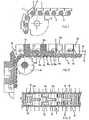
- FIG. 2 is a partial section of a portion of chain along the line II-II of FIG. 3 in its left part, and a view outside in its right part.
- the chain according to the invention comprises a conventional chain (11) with joints, the pitch of which may be small enough for the pinion 12 on which it is wound to be of fairly small diameter.
- the number of links is high, but these being of simple shape and manufactured in very large series, their cost is acceptable.
- this conventional chain 11 can only curve in one direction, the flanges 14 of a link thereof, taken at regular intervals, for example one in four, are integral with a block 13 always placed in the same side of the chain 11.
- This block 13 mainly comprises parts 15 and 16 having rectilinear and coplanar faces 17 and 18 which come to tangent the axes 19 of the chain 11.
- the face 17 of part 15 of a block 13a is in contact with an axis 19b corresponding to the flange 14b of the contiguous block 13b, then with two axes 19 corresponding to “free” links And finally, but optionally, with an axis 19a corresponding to the flange 14 of the block 13a considered. It is the same for the face 18 of the part 16, but then on the other side, that is to say towards the other contiguous block 13.
- each block 13 has two parts 16 "backwards” arranged laterally and a part 15 "forward” placed in the center.
- each neighboring link is free to pivot in the direction where its axis 19 moves away from the corresponding face 517 or 18, on the other hand, in the other direction, its movement is stopped when the axis 19 comes into contact against this face 17 or 18.
- the chain therefore has only one possible direction of curvature. As shown in Figure 2, it can freely wind around a pinion 12 of small diameter, while its rigidity against a force perpendicular to the plane of the axes 19 is provided by the blocks 13.
- FIGS. 2 and 3 So that the chain described with reference to FIGS. 2 and 3 has a zero deflection, the position of the faces 17 and 18 relative to the external surface of the axes 19 must be rigorous. However, machining inaccuracies on the one hand, deformations and wear on the other hand can lead to more or less significant "counter-direction" bending of the chain.
- an additional adjustment device is shown in Figures 4 and 5 which are equivalent to Figures 2 and 3 previously described.
- This device consists of a screw 20, or other adjustable stop, mounted in each block 13 and whose head is applied against a bearing face of a contiguous block 13. This screw 20, by taking up the existing compression forces in the external part of the chain, replaces or completes the action of the corresponding part (in the case shown) in the chain portion located between two pinions 12 of support.
- the screw 20 which is not in contact with the corresponding bearing face in the winding zones around the pinions 12, is still not in the zones preceding (or following) these on a length equal to the interval between two flanges 14; thus, only the part 15 ensures the action “antiflexion in these latter zones, which explains the need to maintain it despite the presence of the screw 20 which could be sufficient in the rectilinear zones.
- the chain with only one direction of curvature according to the invention is applicable in numerous and varied assemblies.
- it can serve as a conveyor for goods or luggage, or as a transporter of people; for this the blocks 13 support the elements constituting the working surface of the conveyor or the conveyor, these are for example contiguous plates which form a continuous rectilinear surface.
- FIG. 6 Another example of application shown in Figure 6, consists of a variable speed handrail as described in French patent application No. 2 274 523, consisting of individual handles 21 connected together by a deformable mesh 22 with constant perimeter, where the chain has a direction of curvature according to the invention constitutes both said mesh and a rigid support between two handles.
- the blocks each receive a cover 23 which ensures the continuity of the external surface.
Landscapes
- Engineering & Computer Science (AREA)
- Mechanical Engineering (AREA)
- General Engineering & Computer Science (AREA)
- Chain Conveyers (AREA)
- Escalators And Moving Walkways (AREA)
- Gears, Cams (AREA)
Claims (6)
Applications Claiming Priority (2)
| Application Number | Priority Date | Filing Date | Title |
|---|---|---|---|
| FR7820595 | 1978-07-11 | ||
| FR7820595A FR2431075A1 (fr) | 1978-07-11 | 1978-07-11 | Chaine a un seul sens de courbure et application a une main courante |
Publications (2)
| Publication Number | Publication Date |
|---|---|
| EP0007264A1 EP0007264A1 (de) | 1980-01-23 |
| EP0007264B1 true EP0007264B1 (de) | 1981-12-23 |
Family
ID=9210569
Family Applications (1)
| Application Number | Title | Priority Date | Filing Date |
|---|---|---|---|
| EP79400414A Expired EP0007264B1 (de) | 1978-07-11 | 1979-06-21 | In nur eine Richtung biegsame Kette und Anwendung als Handgriff |
Country Status (7)
| Country | Link |
|---|---|
| US (1) | US4267922A (de) |
| EP (1) | EP0007264B1 (de) |
| JP (1) | JPS5932364B2 (de) |
| CA (1) | CA1135516A (de) |
| DE (1) | DE2961603D1 (de) |
| FR (1) | FR2431075A1 (de) |
| SU (1) | SU895278A3 (de) |
Families Citing this family (10)
| Publication number | Priority date | Publication date | Assignee | Title |
|---|---|---|---|---|
| EP0152639B1 (de) * | 1982-02-22 | 1988-02-10 | Rexnord Inc. | Förderkette für geringen Staudruck |
| JPS60142210U (ja) * | 1984-02-27 | 1985-09-20 | コ−ア株式会社 | 電子部品移送チエ−ン |
| FR2588842B1 (fr) * | 1985-10-21 | 1987-12-31 | Regie Autonome Transports | Dispositif de transport en continu a vitesse variable |
| FR2675135B1 (fr) * | 1991-04-12 | 1993-08-06 | Patin Pierre | Dispositif de transport, notamment a element transporteur a vitesse elevee. |
| FR2692878B1 (fr) * | 1992-06-24 | 1995-07-13 | Patin Pierre | Element de transporteur a vitesse variable. |
| US5263574A (en) * | 1993-04-06 | 1993-11-23 | T.K.F., Inc. | Interlocking flight for conveyor systems |
| US5855271A (en) * | 1995-11-03 | 1999-01-05 | T. K. F., Inc. | Noise and wear reducing apparatus for endless conveyors |
| FR2792626B1 (fr) * | 1999-04-23 | 2001-06-15 | Mediterranee Const Ind | Dispositif formant main courante pour un trottoir roulant accelere |
| DE102004016059B3 (de) * | 2004-04-01 | 2005-11-03 | Aumund-Fördererbau GmbH & Co. KG | Plattenbandförderer mit Schnellmontageeinrichtung |
| CN107876642B (zh) * | 2017-11-24 | 2023-06-30 | 安徽鲲鹏装备模具制造有限公司 | 一种带有可调桥式板链的冷柜内胆支撑机构 |
Family Cites Families (7)
| Publication number | Priority date | Publication date | Assignee | Title |
|---|---|---|---|---|
| US323621A (en) * | 1885-08-04 | Carrier for clay and brick | ||
| DE499428C (de) * | 1930-06-06 | Adolf Schwab | Rostartiger Wanderherd fuer Backoefen zum Backen von Laugenbrezeln | |
| US2498788A (en) * | 1945-06-27 | 1950-02-28 | Morse Chain Co | Timing chain |
| FR1289507A (fr) * | 1961-02-20 | 1962-04-06 | Perfectionnements aux chaînes transporteuses pour appareils de manutention et analogues | |
| DE1171813B (de) * | 1962-05-24 | 1964-06-04 | Ernst Allgeier | Foerdereinrichtung zum Transport von heissen Brammen od. dgl. |
| FR1450845A (fr) * | 1965-07-20 | 1966-06-24 | Haut Rhin Manufacture Machines | Dispositif de transmission |
| FR2207069B1 (de) * | 1972-11-22 | 1977-04-08 | Regie Autonome Transports |
-
1978
- 1978-07-11 FR FR7820595A patent/FR2431075A1/fr active Granted
-
1979
- 1979-06-21 EP EP79400414A patent/EP0007264B1/de not_active Expired
- 1979-06-21 DE DE7979400414T patent/DE2961603D1/de not_active Expired
- 1979-06-28 US US06/052,792 patent/US4267922A/en not_active Expired - Lifetime
- 1979-06-29 CA CA000330893A patent/CA1135516A/fr not_active Expired
- 1979-07-10 JP JP54087388A patent/JPS5932364B2/ja not_active Expired
- 1979-07-11 SU SU792789509A patent/SU895278A3/ru active
Also Published As
| Publication number | Publication date |
|---|---|
| SU895278A3 (ru) | 1981-12-30 |
| DE2961603D1 (en) | 1982-02-11 |
| EP0007264A1 (de) | 1980-01-23 |
| US4267922A (en) | 1981-05-19 |
| CA1135516A (fr) | 1982-11-16 |
| FR2431075A1 (fr) | 1980-02-08 |
| JPS5932364B2 (ja) | 1984-08-08 |
| JPS5540190A (en) | 1980-03-21 |
| FR2431075B1 (de) | 1981-08-14 |
Similar Documents
| Publication | Publication Date | Title |
|---|---|---|
| EP0007264B1 (de) | In nur eine Richtung biegsame Kette und Anwendung als Handgriff | |
| FR2596947A1 (fr) | Dispositif d'avance pour deplacement le long d'un tronc d'arbre | |
| FR2701015A1 (fr) | Système de convoyage en translation/rotation d'un élément support. | |
| EP0468841B1 (de) | Bandförderer | |
| EP2431304B1 (de) | Rollenfördervorrichtung. | |
| FR2614879A1 (fr) | Dispositif pour le transport d'objets, notamment d'emballages de forme rectangulaire | |
| EP0509861A1 (de) | Fördereinrichtung, insbesondere mit Hochgeschwindigkeitsförderstrecke | |
| FR2695854A1 (fr) | Dispositif de fraisage de cavités dans des cartes en matière plastique et d'encartage de circuits intégrés dans lesdites cavités. | |
| FR2837479A1 (fr) | Automate de stockage, de delivrance et de transport de produits | |
| FR2477944A1 (fr) | Perfectionnements aux dispositifs de fixation de billes de bois pour une coupe semi-ronde | |
| EP0229805B1 (de) | Maschine zum automatischen einlegen von erzeugnissen in empfangszellen | |
| CH684217A5 (fr) | Procédé et dispositif pour aligner des fibres optiques. | |
| WO2001032538A1 (fr) | Dispositif de convoyage de palettes | |
| EP0449706A1 (de) | Handhabungssystem für Gegenstände | |
| CH639336A5 (fr) | Dispositif d'alimentation automatique pour une ligne d'emballage de produits alimentaires. | |
| FR2905363A1 (fr) | Convoyeur telescopique, notamment de type a bande. | |
| EP2065318B1 (de) | Bandstruktur für die Handhabung von Produkten oder die Übertragung von Bewegungen und entsprechendes Endlosband für eine solche Struktur | |
| FR2567493A1 (fr) | Procede de convoyage d'objets ou produits, tapis de convoyeur et procede de fabrication | |
| FR3059751A1 (fr) | Lien pour mecanismes de transmission | |
| FR2737513A1 (fr) | Structure de travure destinee en particulier au franchissement de breches par des vehicules et systeme de transfert et de depose d'une telle structure | |
| FR2560535A1 (fr) | Calibreuse pour fruits | |
| FR2516486A1 (fr) | Convoyeur a compartiment permettant de transporter des objets sur un poste de pesee, destine en particulier a classer des fruits | |
| FR2628080A1 (fr) | Convoyeur elevateur du type a ameneurs | |
| EP0323953A1 (de) | Handhabungssystem zum schnellen fördern von schlittenträgern | |
| EP0072824A1 (de) | Kurven förderband |
Legal Events
| Date | Code | Title | Description |
|---|---|---|---|
| PUAI | Public reference made under article 153(3) epc to a published international application that has entered the european phase |
Free format text: ORIGINAL CODE: 0009012 |
|
| AK | Designated contracting states |
Designated state(s): BE CH DE GB IT NL SE |
|
| 17P | Request for examination filed | ||
| ITF | It: translation for a ep patent filed | ||
| GRAA | (expected) grant |
Free format text: ORIGINAL CODE: 0009210 |
|
| AK | Designated contracting states |
Designated state(s): BE CH DE GB IT NL SE |
|
| REF | Corresponds to: |
Ref document number: 2961603 Country of ref document: DE Date of ref document: 19820211 |
|
| PGFP | Annual fee paid to national office [announced via postgrant information from national office to epo] |
Ref country code: CH Payment date: 19840419 Year of fee payment: 6 |
|
| PGFP | Annual fee paid to national office [announced via postgrant information from national office to epo] |
Ref country code: DE Payment date: 19840626 Year of fee payment: 6 |
|
| PGFP | Annual fee paid to national office [announced via postgrant information from national office to epo] |
Ref country code: SE Payment date: 19840630 Year of fee payment: 6 |
|
| PGFP | Annual fee paid to national office [announced via postgrant information from national office to epo] |
Ref country code: NL Payment date: 19870630 Year of fee payment: 9 |
|
| PG25 | Lapsed in a contracting state [announced via postgrant information from national office to epo] |
Ref country code: SE Effective date: 19890622 |
|
| PG25 | Lapsed in a contracting state [announced via postgrant information from national office to epo] |
Ref country code: CH Effective date: 19890630 |
|
| PGFP | Annual fee paid to national office [announced via postgrant information from national office to epo] |
Ref country code: GB Payment date: 19890630 Year of fee payment: 11 |
|
| PGFP | Annual fee paid to national office [announced via postgrant information from national office to epo] |
Ref country code: BE Payment date: 19890714 Year of fee payment: 11 |
|
| PG25 | Lapsed in a contracting state [announced via postgrant information from national office to epo] |
Ref country code: NL Effective date: 19900101 |
|
| NLV4 | Nl: lapsed or anulled due to non-payment of the annual fee | ||
| REG | Reference to a national code |
Ref country code: CH Ref legal event code: PL |
|
| PG25 | Lapsed in a contracting state [announced via postgrant information from national office to epo] |
Ref country code: DE Effective date: 19900301 |
|
| PG25 | Lapsed in a contracting state [announced via postgrant information from national office to epo] |
Ref country code: GB Effective date: 19900621 |
|
| PG25 | Lapsed in a contracting state [announced via postgrant information from national office to epo] |
Ref country code: BE Effective date: 19900630 |
|
| BERE | Be: lapsed |
Owner name: REGIE AUTONOME DES TRANSPORTS PARISIENS Effective date: 19900630 |
|
| GBPC | Gb: european patent ceased through non-payment of renewal fee | ||
| EUG | Se: european patent has lapsed |
Ref document number: 79400414.3 Effective date: 19900412 |
|
| PLBE | No opposition filed within time limit |
Free format text: ORIGINAL CODE: 0009261 |
|
| STAA | Information on the status of an ep patent application or granted ep patent |
Free format text: STATUS: NO OPPOSITION FILED WITHIN TIME LIMIT |