EP0007628A1 - Dispositif de téléalimentation de stations intermédiaires d'une installation de télécommunications - Google Patents
Dispositif de téléalimentation de stations intermédiaires d'une installation de télécommunications Download PDFInfo
- Publication number
- EP0007628A1 EP0007628A1 EP79102651A EP79102651A EP0007628A1 EP 0007628 A1 EP0007628 A1 EP 0007628A1 EP 79102651 A EP79102651 A EP 79102651A EP 79102651 A EP79102651 A EP 79102651A EP 0007628 A1 EP0007628 A1 EP 0007628A1
- Authority
- EP
- European Patent Office
- Prior art keywords
- feed
- constant current
- remote
- circuit arrangement
- supply
- Prior art date
- Legal status (The legal status is an assumption and is not a legal conclusion. Google has not performed a legal analysis and makes no representation as to the accuracy of the status listed.)
- Granted
Links
- 230000005540 biological transmission Effects 0.000 claims abstract description 15
- 238000004891 communication Methods 0.000 claims abstract description 6
- 238000012544 monitoring process Methods 0.000 claims description 10
- 238000012806 monitoring device Methods 0.000 claims description 8
- 239000000654 additive Substances 0.000 claims description 5
- 230000000996 additive effect Effects 0.000 claims description 5
- 238000005516 engineering process Methods 0.000 claims description 2
- 238000000034 method Methods 0.000 description 2
- 239000013307 optical fiber Substances 0.000 description 2
- 239000004020 conductor Substances 0.000 description 1
- 230000002950 deficient Effects 0.000 description 1
- 238000013461 design Methods 0.000 description 1
- 238000001514 detection method Methods 0.000 description 1
- 238000011161 development Methods 0.000 description 1
- 230000000694 effects Effects 0.000 description 1
- 238000005259 measurement Methods 0.000 description 1
- 238000012986 modification Methods 0.000 description 1
- 230000004048 modification Effects 0.000 description 1
- 239000013642 negative control Substances 0.000 description 1
- 239000013641 positive control Substances 0.000 description 1
- 210000003462 vein Anatomy 0.000 description 1
Images


Classifications
-
- H—ELECTRICITY
- H04—ELECTRIC COMMUNICATION TECHNIQUE
- H04B—TRANSMISSION
- H04B3/00—Line transmission systems
- H04B3/02—Details
- H04B3/44—Arrangements for feeding power to a repeater along the transmission line
Definitions
- the invention relates to a circuit arrangement for the remote supply of intermediate points of a device of the communication technology, by means of direct current series supply, whereby in a remote supply circuit a series connection of two constant current sources provided in the supply points of the message transmission device and connected to one another via a pair of supply wires is provided, and each of the two constant current sources in this way is dimensioned that it can supply the entire transmission path.
- Such a circuit arrangement is e.g. from "The Post Office Electrical Engineers' Journal", Vol. 66, Part 3, Oct. 1973, pages 135 to 137.
- a circuit which is used to close a remote feed loop for row-fed substations in the event of route interruptions.
- the unoccupied substations each consist of two amplifiers fed in parallel for both directions.
- a relay coil and the consumer resistances of the amplifiers are looped into different remote supply current paths in each intermediate amplifier point.
- the cross-connection with the relay contact is made via a switch circuit, each consisting of a series connection of at least two diodes connected in parallel with the consumer resistors and the relay coil.
- the additional switch is a four-pole connector, which is connected with a pair of terminals to the first part of the remote feed loop or the pair of feed wires facing the signal source and the second part facing away from the feed source.
- the relay coil and thus the one longitudinal branch of the four-pole is inserted alternately in one or the other remote supply current path from the intermediate amplifier point to the intermediate amplifier point and the energy flow direction in the remote feed loop is always the same, there is a change in the energy flow direction for the alternately looped-in four-pole circuit.
- the object of the invention is to design a circuit arrangement of the type mentioned at the outset, in which neither errors in one of the two feed points nor a short circuit on the feed wire pair have a disruptive effect on the energy supply of the intermediate points, so that errors are reported and also located with the simplest possible means can be.
- the circuit arrangement for solving this problem is designed such that the two constant current sources are set to different current values and that at least one device for monitoring the output voltage is connected to one of the two constant current sources, in particular to the constant current source set to the lower current value. In this way, a connection between the two feed wires can be seen at least in one of the two feed points.
- the circuit arrangement is designed in such a way that a switching additive which is effective for both directions of energy flow is provided in the intermediate points, so that a connection of the feed wires which can be established by means of the monitoring device is brought about even when the remote feed circuit is interrupted.
- a switching additive which is effective for both directions of energy flow is provided in the intermediate points, so that a connection of the feed wires which can be established by means of the monitoring device is brought about even when the remote feed circuit is interrupted.
- the supply devices of the intermediate points are designed for a range of the supply current which includes the current values to which the two remote supply devices are set.
- the device for monitoring the output voltage expediently monitors the level of the DC voltage in the event that it is effective with the constant current source set to the smaller current value.
- the device for monitoring the output voltage in the event that it is effective with the constant current source set to the larger current value, can monitor changes in the DC voltage.
- FIG. 1 shows an arrangement for uninterrupted remote feeding of intermediate points of a device for message transmission, which are in particular intermediate regenerators of an optical fiber link.
- the remote feed circuit runs over feed wires, which may be provided in addition to the optical fibers.
- the remote feed circuit can be connected in particular via the inner conductor the cable runs.
- the intermediate points 21 ... 23 of the message transmission device are fed with a constant direct current I by means of series feeding.
- a converter 5 is provided for supplying the operating voltage for the consumers, the input of which is fed by the direct current direct current I.
- the converter 5 supplies a line amplifier 4, which contains a single amplifier for each transmission direction of the communication link.
- the two individual amplifiers which is not shown in the figure, are fed in particular in parallel, so that a parallel series supply results for the circuit arrangement for remote feeding.
- the inverters 5 are operated in series connection in the remote feed circuit.
- the inputs of the converter 5 are alternately connected from one intermediate point to another in the one and the other remote feed current path in order to achieve an even load distribution. However, if necessary, they can also be inserted into one and the same remote feed wire or one and the same remote feed current path.
- the pair of remote feed wires is connected at both ends to a remote power supply device 11 or 12, so that there is a two-sided supply with device redundancy present at the same time.
- a series connection of the two remote power supply devices 11 and 12 is effective in the remote power supply circuit.
- Each of these two remote feed devices is able to supply the entire remote feed section according to the principle of the so-called "hot reserve".
- the load distribution can be set arbitrarily in undisturbed operation, namely randomly according to the inevitable tolerances of the remote supply devices; this is irrelevant for the supply of constant current.
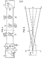
- Fig. 2 shows the potential curve on the long-distance feed line.
- the straight line pair a shows the course during undisturbed operation and the straight line pair b for a failure of the remote power supply device 12.
- the load distribution between the two remote power supply devices is random.
- the remote power supply 11 delivers the entire power.
- An uninterrupted operation of the intermediate points even in the event of an interruption at a point X of the pair of remote feed wires is achieved in that a switching add-on 3 is provided in each intermediate point, which, in the event of an interruption of one or both feed wires, closes the remote feed circuit before the point of interruption X so that the Converter 5 of the intermediate points can be supplied further.
- a switch accessory is shown in more detail in FIGS. 6 and 7.
- the associated potential curve on the long-distance feed line is shown in FIG. 3 with the straight line pair d in the event of an interruption at point X.
- circuit arrangement shown in FIG. 1 offers a particularly advantageous possibility of transmitting faults on the pair of feed wires to the location of one of the two feed points, namely by using the remote feed itself to observe the route conditions.
- the circuit arrangement is / is formed so that a fault detection and fault location is possible.
- the remote supply devices 11 and 12 can be adjusted with regard to the feed current.
- the feed current is set to the nominal value IN.
- the other remote supply device 11, on the other hand, is set to a constant current which is 5% below the value of the nominal current IN. Due to the higher constant current IN impressed by the other remote power supply device 12, none or is not present at the output of the remote power supply device 11 a low negative voltage.
- This monitoring device can also be part of the remote supply device.
- the feed points 11 and 12 are each provided with an actuator by means of which the constant current can be controlled.
- the monitoring device 6 is provided with a control device, not shown, which automatically adjusts the constant current of the feed point 11 to the current value IN 5% via the connection 9.
- FIG. 5 shows for the circuit arrangement according to FIG. 4 the course of the potential on the long-distance feed line in the case of undisturbed operation or in the event of a line fault at point X.
- the straight pair e shows the potential course in the case of undisturbed operation.
- the remote power supply 12 feeds the entire route with the nominal current IN.
- Line pair f shows the potential curve in the event of an error.
- the remote supply device 11 feeds up to point X with a current of the size IN -5% and the remote supply device 12 feeds up to point X with the nominal value IN of the supply current.
- the second remote feed device 12 which supplies the feed current IN, takes over the supply of the full remote feed path, the potential zero point being in the remote feed device 11, which is set to 95% of the nominal remote feed current. 5 shows, the output voltage of the remote power supply 11 has the value 0 V; if necessary, it can be slightly negative.
- the remote feed device 11 feeds up to this point. In this case its output voltage is higher. as 0 V. This is the criterion for reporting the route error.
- the remote power supply 12 also feeds up to the connection point, so that the entire route remains supplied.
- the inverters 5 are able to deliver the required operating voltages at 95% of the nominal feed current or to compensate for the slight current increase associated with 100% nominal feed current.
- the fault is located by simply reading the voltage display on the remote supply device 11. If monitoring at the location of the remote supply device 12 is desired, changes in the output voltage are expediently monitored and corresponding change messages are stored.
- the Switching accessories that connect the wires in the event of an interruption, designed and dimensioned so that they only have a voltage drop at the connection point that is significantly less than the voltage drop of an amplifier field.
- a switching add-on 3 is provided which connects the two feed wires in the event of an interruption of the remote feed loop in such a way that the associated intermediate amplifier continues to be supplied via the uninterrupted direction and the interrupted direction is monitored in the process. After eliminating the interruption, the wire connection on the switching accessory is automatically removed.
- FIG. 6 shows the structure of this switching additive when using a sensitive relay 81.
- the additional switch 31 is switched on one side with the connections A and C, on the other side with the connections B and D in the remote feed circuit.
- the connections A and B, to which the converter 5 is connected, are connected via a series connection of the diodes 71 and 72.
- Relay 81 is located between connections C and D and is bridged by the series connection of diodes 74 and 75.
- the series connection of the resistor 73 with the normally closed contact 82 of the relay 81 lies between the connection points of the two diodes 71, 72 and 74, 75.
- the converter 5 continues to be operated from the direction of the connections AC.
- the feed current then flows coming from connection A via the input of the converter 5 (diode 71 blocks), diode 72 and transverse resistor 73 to the closed relay contact 82, and from there via diode 74 and terminal C back again.
- the relay 81 monitors the incorrect direction of the connections BD.
- the converters 5 continue to be operated from the direction of the connections B-D.
- the current flow then runs from connection D via diode 75, contact 82, resistor 73, diode 71, converter 5 to connection B.
- Relay 81 now monitors the faulty direction of connections A-B.
- Fig. 7 shows a modification of the switching additive shown in Fig. 6 when using a less sensitive relay 81'-.
- the switching additive according to FIG. 7 also differs from that according to FIG. 6 in that instead of the resistor 73 replaced by a direct connection, a resistor 78 or 79 is arranged in series with the diodes 74 and 75.
- the diode bridge 71, 72, 74, 75 of the switching add-on shown in FIG. 5 and FIG. 6 advantageously enables the same method of operation regardless of the feed direction with only one relay 81 or 81 '.
Landscapes
- Engineering & Computer Science (AREA)
- Computer Networks & Wireless Communication (AREA)
- Signal Processing (AREA)
- Cable Transmission Systems, Equalization Of Radio And Reduction Of Echo (AREA)
- Monitoring And Testing Of Transmission In General (AREA)
- Devices For Supply Of Signal Current (AREA)
Applications Claiming Priority (2)
| Application Number | Priority Date | Filing Date | Title |
|---|---|---|---|
| DE2833017 | 1978-07-27 | ||
| DE2833017A DE2833017C3 (de) | 1978-07-27 | 1978-07-27 | Schaltungsanordnung zur Fernspeisung von Zwischenstellen einer Einrichtung der Nachrichtenübertragungstechnik |
Publications (2)
| Publication Number | Publication Date |
|---|---|
| EP0007628A1 true EP0007628A1 (fr) | 1980-02-06 |
| EP0007628B1 EP0007628B1 (fr) | 1981-04-29 |
Family
ID=6045550
Family Applications (1)
| Application Number | Title | Priority Date | Filing Date |
|---|---|---|---|
| EP79102651A Expired EP0007628B1 (fr) | 1978-07-27 | 1979-07-25 | Dispositif de téléalimentation de stations intermédiaires d'une installation de télécommunications |
Country Status (4)
| Country | Link |
|---|---|
| EP (1) | EP0007628B1 (fr) |
| JP (1) | JPS5520099A (fr) |
| DE (2) | DE2833017C3 (fr) |
| DK (1) | DK316479A (fr) |
Cited By (3)
| Publication number | Priority date | Publication date | Assignee | Title |
|---|---|---|---|---|
| EP0030006A1 (fr) * | 1979-11-30 | 1981-06-10 | Siemens Aktiengesellschaft | Dispositif de circuit de téléalimentation de stations intermédiaires d'une installation de télécommunications avec surveillance de la tension de sortie d'au moins une unité d'alimentation |
| EP0030004A1 (fr) * | 1979-11-30 | 1981-06-10 | Siemens Aktiengesellschaft | Dispositif de circuit de téléalimentation de stations intermédiaires d'une installation de télécommunication au moyen d'une alimentation sérielle de courant continu |
| AU624233B2 (en) * | 1989-04-19 | 1992-06-04 | Kabushiki Kaisha Toshiba | Fault detecting system for duplexing type local area networks |
Families Citing this family (2)
| Publication number | Priority date | Publication date | Assignee | Title |
|---|---|---|---|---|
| DE3003515C2 (de) * | 1980-01-31 | 1984-07-19 | Siemens AG, 1000 Berlin und 8000 München | Schaltungsanordnung zum Schließen der Fernspeiseschleife einer Fernspeiseeinrichtung |
| JPS5799042A (en) * | 1980-12-11 | 1982-06-19 | Nec Corp | Submarine relay system |
Citations (6)
| Publication number | Priority date | Publication date | Assignee | Title |
|---|---|---|---|---|
| DE1462219B2 (de) * | 1965-09-15 | 1971-05-19 | Siemens AG, 1000 Berlin u 8100 München | Fernspeisesystem fuer gleichstrom reihenspeisung |
| DE1762599C (de) * | 1971-06-09 | Schaltung zum Schließen der Fern speiseschleife fur reihengespeiste, aus je zwei parallel gespeisten Verstarkern fur beide Richtungen bestehende, unbemannte Unterstationen bei Streckenunterbrechun | ||
| DE2260335A1 (de) * | 1971-12-15 | 1973-06-28 | Post Office | Anordnung fuer die einspeisung von leistung in ein fernmeldesystem |
| DE1902090B2 (de) * | 1966-03-31 | 1975-07-31 | Siemens Ag, 1000 Berlin Und 8000 Muenchen | Verfahren zum Aufrechterhalten der Fernspeisung bei Streckenunterbrechungen |
| DE2531096B2 (de) * | 1975-07-11 | 1977-04-28 | Siemens AG, 1000 Berlin und 8000 München | Gleichstromfehlerortung fuer symmetrische uebertragungssysteme |
| DE2620348B1 (de) * | 1976-05-07 | 1977-06-08 | Siemens Ag | Schaltungsanordnung zur ortung von unterbrechungen auf nachrichtenuebertragungsstrecken |
-
1978
- 1978-07-27 DE DE2833017A patent/DE2833017C3/de not_active Expired
-
1979
- 1979-07-25 EP EP79102651A patent/EP0007628B1/fr not_active Expired
- 1979-07-25 DE DE7979102651T patent/DE2960311D1/de not_active Expired
- 1979-07-26 DK DK316479A patent/DK316479A/da not_active Application Discontinuation
- 1979-07-27 JP JP9511379A patent/JPS5520099A/ja active Pending
Patent Citations (6)
| Publication number | Priority date | Publication date | Assignee | Title |
|---|---|---|---|---|
| DE1762599C (de) * | 1971-06-09 | Schaltung zum Schließen der Fern speiseschleife fur reihengespeiste, aus je zwei parallel gespeisten Verstarkern fur beide Richtungen bestehende, unbemannte Unterstationen bei Streckenunterbrechun | ||
| DE1462219B2 (de) * | 1965-09-15 | 1971-05-19 | Siemens AG, 1000 Berlin u 8100 München | Fernspeisesystem fuer gleichstrom reihenspeisung |
| DE1902090B2 (de) * | 1966-03-31 | 1975-07-31 | Siemens Ag, 1000 Berlin Und 8000 Muenchen | Verfahren zum Aufrechterhalten der Fernspeisung bei Streckenunterbrechungen |
| DE2260335A1 (de) * | 1971-12-15 | 1973-06-28 | Post Office | Anordnung fuer die einspeisung von leistung in ein fernmeldesystem |
| DE2531096B2 (de) * | 1975-07-11 | 1977-04-28 | Siemens AG, 1000 Berlin und 8000 München | Gleichstromfehlerortung fuer symmetrische uebertragungssysteme |
| DE2620348B1 (de) * | 1976-05-07 | 1977-06-08 | Siemens Ag | Schaltungsanordnung zur ortung von unterbrechungen auf nachrichtenuebertragungsstrecken |
Cited By (3)
| Publication number | Priority date | Publication date | Assignee | Title |
|---|---|---|---|---|
| EP0030006A1 (fr) * | 1979-11-30 | 1981-06-10 | Siemens Aktiengesellschaft | Dispositif de circuit de téléalimentation de stations intermédiaires d'une installation de télécommunications avec surveillance de la tension de sortie d'au moins une unité d'alimentation |
| EP0030004A1 (fr) * | 1979-11-30 | 1981-06-10 | Siemens Aktiengesellschaft | Dispositif de circuit de téléalimentation de stations intermédiaires d'une installation de télécommunication au moyen d'une alimentation sérielle de courant continu |
| AU624233B2 (en) * | 1989-04-19 | 1992-06-04 | Kabushiki Kaisha Toshiba | Fault detecting system for duplexing type local area networks |
Also Published As
| Publication number | Publication date |
|---|---|
| EP0007628B1 (fr) | 1981-04-29 |
| DE2833017A1 (de) | 1980-02-07 |
| DE2833017B2 (de) | 1980-10-02 |
| JPS5520099A (en) | 1980-02-13 |
| DE2833017C3 (de) | 1981-08-27 |
| DK316479A (da) | 1980-01-28 |
| DE2960311D1 (en) | 1981-08-06 |
Similar Documents
| Publication | Publication Date | Title |
|---|---|---|
| DE69604499T2 (de) | Verbesserungen bei der leistungsschaltung von verteilereinheiten für faseroptische kabel | |
| DE4325663A1 (de) | Stromversorgungsschalter-Relaisschaltung | |
| EP0007626B1 (fr) | Circuit pour l'alimentation à distance des stations intermédiaires d'un dispositif utilisé dans la technique de transmission d'information | |
| EP0007628B1 (fr) | Dispositif de téléalimentation de stations intermédiaires d'une installation de télécommunications | |
| DE2942660A1 (de) | Stabilisierte gleich-gleichspannungsumsetzeinheit | |
| EP0097233A2 (fr) | Montage pour la mise en marche de la téléalimentation de consommateurs électriques | |
| DE3121409A1 (de) | Blockeinschub | |
| DE2620348C2 (de) | Schaltungsanordnung zur Ortung von Unterbrechungen auf Nachrichtenübertragungsstrecken | |
| EP0033471A1 (fr) | Montage pour la fermeture de la boucle de téléalimentation d'une installation pour alimentation à distance | |
| EP0012238B1 (fr) | Circuit pour fermer la boucle de téléalimentation pour stations de répéteur intermédiaires alimentées en série | |
| DE3145437A1 (de) | Schalteinrichtung fuer einrichtung zur wechselstrom-parallel-fernspeisung | |
| EP0030004B1 (fr) | Dispositif de circuit de téléalimentation de stations intermédiaires d'une installation de télécommunication au moyen d'une alimentation sérielle de courant continu | |
| EP0030006B1 (fr) | Dispositif de circuit de téléalimentation de stations intermédiaires d'une installation de télécommunications avec surveillance de la tension de sortie d'au moins une unité d'alimentation | |
| DE3035515C2 (fr) | ||
| EP0249220A1 (fr) | Montage pour le raccordement automatique des liaisons de courant d'alimentation à distance d'une boucle d'alimentation à distance | |
| DE3242000A1 (de) | Schaltungsanordnung zur fehlerortung in verbindung mit einer einrichtung zur fernspeisung von elektrischen verbrauchern | |
| EP0118879B1 (fr) | Unité d'alimentation à distance pour un dispositif d'alimentation en série en courant continu | |
| DE19844185A1 (de) | Busleitungssystem | |
| DE2536219C2 (de) | Fernstromversorgung für Übertragungsstrecken großer Länge | |
| DE3308741C2 (de) | Schaltungsanordnung zur Fernspeisung von elektrischen Verbrauchern mittels Gleichstrom-Reihenspeisung | |
| EP0096743B1 (fr) | Montage pour la fermeture de la boucle de téléalimentation d'une installation pour alimentation à distance | |
| DE1487294C3 (de) | Einrichtung zum selbsttätigen Einpegeln, zur Überwachung, Fehlererkennung und Fehlerortung von ferngespeisten Trägerfrequenzleitungen | |
| DE3211518C2 (de) | Schaltungsanordnung mit einem Relais zum selbsttätigen Verbinden der beiden Fernspeisestrompfade einer unterbrochenen Fernspeiseschleife | |
| DE1265215B (de) | Schaltungsanordnung zur Fehlerortung von Unterbrechungen in Fernspeiseschleifen von Traegerfrequenz-Weitverkehrssystemen | |
| DE1299731B (de) | Fernmeldeleitungsverstaerker mit einem der Signalfrequenz parallelgeschalteten Gleichstrompfad |
Legal Events
| Date | Code | Title | Description |
|---|---|---|---|
| PUAI | Public reference made under article 153(3) epc to a published international application that has entered the european phase |
Free format text: ORIGINAL CODE: 0009012 |
|
| AK | Designated contracting states |
Designated state(s): BE DE FR GB IT NL |
|
| 17P | Request for examination filed | ||
| ITF | It: translation for a ep patent filed | ||
| GRAA | (expected) grant |
Free format text: ORIGINAL CODE: 0009210 |
|
| AK | Designated contracting states |
Designated state(s): BE FR GB IT NL |
|
| RBV | Designated contracting states (corrected) |
Designated state(s): BE FR GB IT NL |
|
| REF | Corresponds to: |
Ref document number: 2960311 Country of ref document: DE Date of ref document: 19810806 |
|
| PGFP | Annual fee paid to national office [announced via postgrant information from national office to epo] |
Ref country code: FR Payment date: 19840720 Year of fee payment: 6 |
|
| PGFP | Annual fee paid to national office [announced via postgrant information from national office to epo] |
Ref country code: BE Payment date: 19840930 Year of fee payment: 6 |
|
| PGFP | Annual fee paid to national office [announced via postgrant information from national office to epo] |
Ref country code: NL Payment date: 19860731 Year of fee payment: 8 |
|
| BERE | Be: lapsed |
Owner name: SIEMENS A.G. BERLIN UND MUNCHEN Effective date: 19870731 |
|
| PG25 | Lapsed in a contracting state [announced via postgrant information from national office to epo] |
Ref country code: NL Effective date: 19880201 |
|
| NLV4 | Nl: lapsed or anulled due to non-payment of the annual fee | ||
| PG25 | Lapsed in a contracting state [announced via postgrant information from national office to epo] |
Ref country code: FR Free format text: LAPSE BECAUSE OF NON-PAYMENT OF DUE FEES Effective date: 19880331 |
|
| GBPC | Gb: european patent ceased through non-payment of renewal fee | ||
| REG | Reference to a national code |
Ref country code: FR Ref legal event code: ST |
|
| PG25 | Lapsed in a contracting state [announced via postgrant information from national office to epo] |
Ref country code: GB Free format text: LAPSE BECAUSE OF NON-PAYMENT OF DUE FEES Effective date: 19881118 |
|
| PG25 | Lapsed in a contracting state [announced via postgrant information from national office to epo] |
Ref country code: BE Effective date: 19890731 |
|
| PLBE | No opposition filed within time limit |
Free format text: ORIGINAL CODE: 0009261 |
|
| STAA | Information on the status of an ep patent application or granted ep patent |
Free format text: STATUS: NO OPPOSITION FILED WITHIN TIME LIMIT |