EP0007660A1 - System zum Auffinden und Bearbeiten von auf Microfiches festgelegten Daten, das maschinell und visuell lesbare Microfiches verwendet - Google Patents
System zum Auffinden und Bearbeiten von auf Microfiches festgelegten Daten, das maschinell und visuell lesbare Microfiches verwendet Download PDFInfo
- Publication number
- EP0007660A1 EP0007660A1 EP79200373A EP79200373A EP0007660A1 EP 0007660 A1 EP0007660 A1 EP 0007660A1 EP 79200373 A EP79200373 A EP 79200373A EP 79200373 A EP79200373 A EP 79200373A EP 0007660 A1 EP0007660 A1 EP 0007660A1
- Authority
- EP
- European Patent Office
- Prior art keywords
- microfiche
- information
- row
- sensor
- scanner
- Prior art date
- Legal status (The legal status is an assumption and is not a legal conclusion. Google has not performed a legal analysis and makes no representation as to the accuracy of the status listed.)
- Withdrawn
Links
Images




Classifications
-
- G—PHYSICS
- G06—COMPUTING OR CALCULATING; COUNTING
- G06K—GRAPHICAL DATA READING; PRESENTATION OF DATA; RECORD CARRIERS; HANDLING RECORD CARRIERS
- G06K17/00—Methods or arrangements for effecting co-operative working between equipments covered by two or more of main groups G06K1/00 - G06K15/00, e.g. automatic card files incorporating conveying and reading operations
- G06K17/0016—Selecting or retrieving of images by means of their associated code-marks, e.g. coded microfilm or microfiche
-
- G—PHYSICS
- G06—COMPUTING OR CALCULATING; COUNTING
- G06K—GRAPHICAL DATA READING; PRESENTATION OF DATA; RECORD CARRIERS; HANDLING RECORD CARRIERS
- G06K19/00—Record carriers for use with machines and with at least a part designed to carry digital markings
- G06K19/06—Record carriers for use with machines and with at least a part designed to carry digital markings characterised by the kind of the digital marking, e.g. shape, nature, code
- G06K19/08—Record carriers for use with machines and with at least a part designed to carry digital markings characterised by the kind of the digital marking, e.g. shape, nature, code using markings of different kinds or more than one marking of the same kind in the same record carrier, e.g. one marking being sensed by optical and the other by magnetic means
-
- G—PHYSICS
- G11—INFORMATION STORAGE
- G11B—INFORMATION STORAGE BASED ON RELATIVE MOVEMENT BETWEEN RECORD CARRIER AND TRANSDUCER
- G11B27/00—Editing; Indexing; Addressing; Timing or synchronising; Monitoring; Measuring tape travel
- G11B27/10—Indexing; Addressing; Timing or synchronising; Measuring tape travel
- G11B27/19—Indexing; Addressing; Timing or synchronising; Measuring tape travel by using information detectable on the record carrier
- G11B27/28—Indexing; Addressing; Timing or synchronising; Measuring tape travel by using information detectable on the record carrier by using information signals recorded by the same method as the main recording
-
- G—PHYSICS
- G11—INFORMATION STORAGE
- G11B—INFORMATION STORAGE BASED ON RELATIVE MOVEMENT BETWEEN RECORD CARRIER AND TRANSDUCER
- G11B7/00—Recording or reproducing by optical means, e.g. recording using a thermal beam of optical radiation by modifying optical properties or the physical structure, reproducing using an optical beam at lower power by sensing optical properties; Record carriers therefor
- G11B7/002—Recording, reproducing or erasing systems characterised by the shape or form of the carrier
- G11B7/0033—Recording, reproducing or erasing systems characterised by the shape or form of the carrier with cards or other card-like flat carriers, e.g. flat sheets of optical film
Definitions
- This invention relates to microfiche information retrieval techniques, and is more particularly concerned with the provision and retrieval of digital information on a microfiche card, which information is to be retrieved for data processing purposes in, for example, a parts management and inventory control system or in an accounts management and checking system.
- control information on reel or cartridge or microfilm to identify frames along the length of the microfilm. This information may be in the form of alphanumeric characters which are visually read on a trial and error basis until the desired frame is properly positioned for reading in a viewer. It is also well known in the art to place control information along the edge of a strip of microfilm to be read by an optical scanner in order to place a desired frame within the viewing field of a viewer. It is also known in the art to mechanically address and position a microfiche transport, on an x-y basis, in order to register a desired frame of information within the viewing field of a viewer; however, mechanical techniques are expensive, and the expense increases with increased accuracy of registration.
- microfiche cards used in parts management and inventory control systems such as may be used in the retail, automotive and farm equipment industries, or accounts, credit check and signature card systems in the banking industry
- a card is placed on an x-y transport, generally manually operated, and the desired frame is obtained, again by a trial and error method through repeated repositionings of the card until the desired frame appears on the viewer.
- microfiche cards have been limited to providing, in conjunction with parts catalogues and the like, visually readable graphic illustrations and/or alphanumeric information, such as generally found in retail catalogue and parts ordering systems.
- alphanumeric and digital codes have been provided on reel- type microfilm for visual or electronic observation, while microfiche cards have been provided with visual indicators to identify the position of a frame within a matrix of frames on a card.
- the primary object of the present invention is to provide a management system for parts and accounts information retrieval.
- a more specific object of the invention is to provide a microfiche information retrieval system which utilizes a data base which is easily and inexpensively up-dated.
- Another specific object of the invention is to provide a new and improved parts management and inventory control system.
- Another specific object of the invention is to provide a new and improved bank and credit account information checking system.
- microfiche or microfiche cards two basic types of cut microfiche, hereinafter simply called microfiche or microfiche cards, are provided as a data base.
- One type of microfiche card, called a "viewer microfiche” bears graphic information and digital information, the differences between such information being discussed below.
- viewer microfiche two types of viewer microfiche are provided:
- the second type of microfiche is a totally digital microfiche which bears machine readable codes. More specifically, in a parts management and inventory control system (PMIC) the second type of microfiche is called a "price" microfiche and bears digital codes which indicate manufacturer's part number, locator number, current price and if the part is presently in stock.
- PMIC parts management and inventory control system
- the locator number may serve two purposes:
- the PMIC system and related banking and retail catalogue systems are based upon a concept having the following features:
- a microfiche card generally includes a header and a body,
- the header usually bears some type of text which identifies the card and its general content, while the body of the card bears the information sought to be retrieved.
- the information to be retrieved may be graphic information or, according to the present invention, digital information.
- a master microfiche has a header comprising a sequential range of manufacturer part numbers and the body of the microfiche comprises the individual part numbers and the respective corresponding system locator numbers.
- the locator numbers may denote physical stock locations, as well as serve the primary function of identifying the corresponding price microfiche and addresses of the price microfiche inventory and price information.
- a parts microfiche has a header which carries manufacturer model and part numbers, while the body bears graphic information concerning the parts, manufacturer part number, general descriptions of the parts, and corresponding locator numbers.
- the price microfiche bears a price microfiche number on the header, while manufacturer number information and current sale price are carried on the body portion of the microfiche.
- a digital microfiche (corresponding to a PMIC price microfiche) may include account information in a machine readable form only, and may be accessed by appropriate addressing, such as by bank or credit card account number, and provide an account check in complete privacy from all persons, including the clerk or teller, as the case may be, who is seeking such information.
- digital information is generally meant to identify marks, either opaque-on-clear or clear-on-opaque
- graphics information is generally meant to identify all other forms of information including alphanumeric information, drawings and the like.
- contrasting colors may be used for digital and/or graphic information when such display is desired, such as for example in television applications.
- the present invention may advantageously be embodied in a system which comprises the aforementioned master, parts and price microfiche and apparatus for retrieving the information stored on such microfiche.
- a viewer microfiche master of parts
- the locator number includes a price microfiche identification number to identify the pertinent price microfiche.
- the price microfiche is selected and placed in a scanner. Then, the locator number is keyed into the system to , cause the scanner to access the price inventory information concerning that particular part.
- the price and inventory information is displayed by means of, for example, a light emitting diode (LED) display unit.
- a printer for making a permanent record of the transaction and, in the case of an order, or a cancellation due to newly-received previously ordered parts, the transaction information is stored, at least on a temporary basis, for later communication to a central parts management computer.
- Such storage may advantageously be made with a magnetic tape unit and communicate to the central computer - by way of the commercial telephone network by utilizing either a modulator-demodulator (MODEM) unit or a coder- decoder (CODEC) arrangement. All digital inter-unit and inter-network transmission may be accomplished with a specific digital code, such as the ASCII code.
- a price microfiche also called a "scanner" microfiche is intended to define a convenient, read-only, transportable, filable, data base constructed in standard microfiche form.
- the microfiche may bear written, graphic, audio or other information.
- the scanner microfiche may carry the information in digital or analog form and can be read with a scanner, transformed electronically to any desirable form, and can be displayed or used in any desired manner, or can be read with a TV camera and processed as a standard TV picture of signals.
- the scanner microfiche is employed to provide data for another machine, (such as a computer) to accept and store, the entire microfiche may contain data only, an incremental encoding, as disclosed below, is not needed, except perhaps for initial alignment or periodic alignment purposes.
- a viewer microfiche is also a convenient, read-only, transportable, filable, data base in standard microfiche form.
- the information content may be written, graphic, audio, or other information.
- the scanner microfiche it is intended that the viewer microfiche have the information to be retrieved by projection onto a viewing screen.
- the present invention utilizes the possibility of generating, "printing" and distributing digital information at less expense and at greater speed than heretofore known.
- a particular advantage of all the microfiche cards used in the present invention is that information may be distributed, and up-dated, by mail, on an inexpensive basis, to provide a current inexpensive data base.
- the PMIC system was designed with an overall view of improving product or parts management and inventory control. More specifically, the PMIC system services seven areas which are critical to efficient parts management and inventory control, namely:
- a customer's account may be checked, upon the presentation of a personal check or credit card, for example, by utilizing the account number to address a digitized scanner microfiche.
- the information read from the fiche may readily be converted into alphanumeric account identification and account status information and displayed on a LED unit, with complete privacy as to the name of the customer.
- rapid credit checks can be made through the simple use of digitized microfiche cards, and a scanner which has an input keyboard and an output display unit. It is also possible to place bank account signature cards on viewer microfiche and key in the customer's account number so as to compare an endorsement on a withdrawal slip, for example, with the signature of the customer as seen on the viewer.
- FIGS. 4-7 illustrate various techniques of manually-generated and COM-generated data, and techniques for ensuring alignment between the data to be retrieved and a sensor.
- a microfiche card 50 is generally illustrated in FIG. 5 as comprising a body 52 composed of a plurality of information storage areas 54, and a header 56.
- a linear photosensor is oriented transversely to the long dimension of the microfiche.
- the senor In apparatus which has been constructed, the sensor is placed in direct contact with the microfiche card.
- an optical system may be employed to project the microfiche images on a sensor. The use of an optical system is determined by the particular application.
- the sensor may comprise a single continuous line of photocells fabricated as a single unit that spans the entire width dimension, 105mm for example, of the microfiche card, or the sensor can be constructed of any number of segments, each segment containing a number of photocells, with the segments fabricated as a single unit that spans the entire 105mm dimension of the microfiche card.
- the sensor can also be constructed of a single segment, or a number of segments, that span less than a full width of the microfiche card, or a matrix of cells which can sense a block of data, or a linear sensor in combination with a TV camera.
- the light source that activates the sensor is located on the same side of a microcard as the sensor, whereas in microfiche applications the microfiche is located between the source and the sensor.
- the entire sensor is moved left-to-right or right- to-left in the long direction of the microfiche. This is, of course, relative motion and in actual practice either the sensor or the card may be the moving element.
- logic circuits control the rate and mode of movement of the sensor.
- the senor (or the transport) is mounted with a pivot, located at the upper end in the case of the sensor, and a device to move the bottom end of the sensor either left or right is provided to bring the sensor in complete alignment with a single vertical line of data that is to be read.
- the drives discussed herein with reference to block diagrams may advantageously with worm gear mechanisms and may utilize, for example, 2 DC servo-motor manufactured by Transcoil, Inc., Part Number K-21-5540-3-2-6-3.
- FIG. 4 a schematic illustration of a storage area 54 illustrates manually-generated information.
- this sample was manually generated, continuous bars have been employed in portions of the coding.
- the same microfiche card can be generated by COM techniques, in which case the bars would not necessarily be continuous.
- FIGS. 4 and 5 contains all digital data and is not typical in the sense that all frames are identical and widely spaced.
- the data which is to be retrieved from the microfiche card are provided as opaque-on-clear or clear-on-opaque marks, here opaque-on-clear marks, in the form of rows of data 58 which are aligned transversely of the microfiche card. Again, contrasting colors can be used.
- the card bears a plurality of centering marks 60, each of which is aligned with a respective data row 58.
- the microfiche card also carries incremental and coding data 62, a start of data code 64, the data field 66, and end of data code 68 and bottom sensor alignment codes 70.
- the card With the exception that the end of data code 68 and the bottom sensor alignment codes 70 are actually provided physically displaced on the codes 60, 62 and 64 on a card, the card is laid out in a plurality of elongate data rows 0--80. It is the incremental encoding 62, however, which identifies and forms the addresses of the data rows 58.
- a storage area 54 1 is illustrated.
- This storage area is quite similar to that of FIG. 4, with the exception that the data field, generally indicated at 78, is COM-generated data. This data may also be manually generated.
- the data field generally indicated at 78
- this type of microfiche card although the same may be employed in the same manner as that of FIG. 4, may be employed as a programming tool in which the data 78 is to be fed step-by-step into another machine, such as a microprocessor, computer or the like.
- the encoding and alignment codes may be provided to ensure alignment at the first data row, such as indicated at 74 and at some other or periodic point or points, such as illustrated at 76.
- the use of the encoding and alignment marks will be best understood from the following detailed description of reading a scanner microfiche card.
- the logic circuits of the scanner apparatus cause the sensor to move across the microfiche card toward the selected data and the logic circuit remember the position of the sensor at all times.
- the sensor first moves to the transverse column of frames within which the selected line of data is to be found. After locating the proper column of frames, the sensor advances until it detects the incremental code within that frame defines the address of the selected data. The sensor then moves ahead until it detects the centering mark for that selected incremental code. The centering mark ensures that at least the top of the sensor will be in alignment with the codes at the selected address.
- the logic circuits now compare bits 5--8 of the incremental code in the top longitudinal rows to bits 77-80 in the bottom longitudinal rows. If these bits do not correspond, bit-for-bit, the sensor is rotated in the proper direction, as determined by the logic circuits that compare the bits, to achieve alignment with the entire selected transverse data row 58.
- the senor When the bits 5--8 correspond, bit-for-bit, with the bits 77-80, the sensor has achieved alignment with the selected transverse data row. As previously mentioned, the sensor is pivotally mounted; however, in the alternative the transport may be pivotally mounted.
- the sensor is now operated to scan the data transversely of the row aligned therewith and makes use of the information codes that are between the start of data code and the end of data code. Any portion of the data between the start of data code and the end of data code may be used, or ignored, as controlled by the logic circuits.
- a keyboard 82 is provided forthe user to enter a desired address and an activating order.
- the keyboard may be a scanned type arrangement as is common in the art, or may be constructed using, for example, a MOSTEK MK 50311 N four function calculator circuit, the necessary additional switches (PRICE, etc.l and a keyboard integrated circuit such as the S 9262 touch control interface manufactured by American Microsystems, Inc.
- the address is fed to and held in an entry register 84 and the activating order is fed to a lock 86 for sequence control.
- the clock 86 is also connected to other elements than illustrated in the drawing, which connections have been omitted for the purpose of clarity, the same being understood to those skilled in the art.
- a column counter 104 and a comparator register 88 determine which direction to drive the sensor to the selected column.
- the sensor After the sensor has found the selected column, the sensor steps ahead until the incremental code it reads compares bit-for-bit with the selected address, then the sensor is stepped ahead in smaller increments until the centering mark of the desired column is detected. The sensor then stops.
- the sensor 98 may count any one of the bars, such as the bar 72 to determine the proper frame, and the remainder of the marks of the code, for example, the longitudinal bars in rows 1--8 may be counted to determine the proper transverse row 58.
- the incremental code and the sensor alignment code are compared in the comparator register 88 and the sensor 98 is pivotally adjusted, as indicated at 100, so that the codes compare bit-for-bit.
- the entire vertical line of data that is a data row 58, is now scanned and abstracted or used by the data processing circuits 96 for output to circuits which are to utilize the digital information.
- the column counter 104 keeps track of the column in which the sensor is positioned.
- the increment counter selects the address out of the scanned data, and the sensor alignment register selects sensor alignment codes from the scanned data to control positioning of the sensor.
- the sensor position drive and the sensor alignment drive area elements which are well known in the art.
- the entire circuit outlined in the broken line may be configured from a microprocessor of the type Motorola MC 6800 P or the Intel 8080 series, while the sensor register 102 may be formed of any standard well known register and the sensor 98 may be constructed from a well known device, such as the Fairchild CCD 17280.
- the keyboard 82 and the entry register 84 are also devices which are well known to those skilled in the art.
- the comparator register includes a portion identified ROM or RAM, for a read only memory (ROM ⁇ or a random access memory (RAM).
- ROM ⁇ or a random access memory RAM
- the microprocessor may include a ROM in which the program is "wired” in.
- ROM ⁇ or a random access memory RAM
- the microprocessor may include a ROM in which the program is "wired” in.
- Motorola device we selected a RAM and it is necessary to feed in a program when the power to the unit is turned on.
- programming of a RAM in a microprocessor or a "wired-in" program for a ROM is well within the skill of those versed in this art.
- the viewer microfiche card is generally illustrated at 110 in FIG. 8 as comprising a plurality of frames 112 formed in a matrix and having spaces between the frames which are scanned by a sensor 114 which is positioned, for example at 45° with respect to the directions of movement of the microfiche card.
- a plurality of tracking lines 116, 118, 120 are provided in the longitudinal direction of the card and a plurality of tracking lines 122, 124 and 126 are provided in the transverse direction of the microfiche card.
- the tracking and code system described herein is one selected for certain of our test purposes, and represents only one of many configurations this scheme can take while still providing the necessary tracking and coding functions.
- the tracking lines 116--126 are not in the viewing areas and are placed on the microfiche card in precise positions relative to the graphic information within the viewing areas 112.
- the lines are projected on the sensor 114 out of the viewing area.
- the sensor 114 may be constructed of approximately 40 individual photocells and is used to detect the lines and other data.
- the sensor 114 is positioned at 45° to the tracking lines to allow a single sensor to detect both vertical and horizontal tracking lines, although two sensors at right angles to the tracking lines could be utilized to perform as well.
- the tracking lines may be either clear lines with a black background, or vice-versa. We have planned to use clear lines with a black background; however, the system will work either way.
- the tracking scheme permits the vertical tracking lines 122, 124 and 126 to be followed in the same manner.
- the tracking technique amounts to a dynamic, or feed-back, registration system.
- the sensor 114 and tracking line position can also be used to provide proportional control. That is, any misalignment, greater than a single cell of the sensor, with respect to the tracking lines, will produce an error signal that can be used to correct the microfiche card position.
- the tracking lines described above allow for moving the microfiche card in a precise matrix or grid pattern in order to automatically access single or partial frames from a microfiche card.
- a frame center code for example the code marks 124, 126 and 128 is placed between two of the tracking lines, for example the tracking lines 118 and 120, while a frame center bar is placed between both the top and middle, and the middle and bottom tracking lines, that is between the tracking lines 116 and 118, and between the tracking lines 118 and 120, here illustrated in the form of two marks 130 and 132.
- the reference 114 diagrammatically illustrates the center line of the sensor, while the line 122 diagrammatically illustrates the center line of the frame.
- there are two channels, Channel A and Channel B provided in which the frame center code is located in Channel B and the frame center bar is located in Channels A and B.
- the frame center code corresponds to the address of the frame in the horizontal direction.
- the microfiche card is moved in a direction such that the relative motion of the sensor is left-to-right in FIG. 10.
- the sensor 114 passes over the frame center code marks 124, 126, 128, the sensor detects the three bits of the frame center code, which the logic circuits interpret to mean that the microfiche is to stop when the sensor detects the bit between the upper tracking line l16 and the middle tracking 118, that is in Channel A and the bit between the middle tracking line l18 and the bottom tracking line 120, which is in Channel B.
- a corner of a frame may be detected in a manner similar to that discussed above with respect to FIG. 9.
- the tracking lines 116, 118, 120 and the tracking lines 122, 124, 126 generally come together at the corner of each frame. Therefore, in the longitudinal direction there is still a Channel A and a Channel B, while in the transverse direction there is a Channel AV and a Channel BV.
- a plurality of frame corner code markings 136, 138 are provided in the Channel B and a plurality of frame corner code markings 140, 142 are provided in the Channel BV, while a frame corner bar is provided in Channel A and Channel B, as illustrated at 144, 146.
- the sensor again symbolically illustrated at 114, detects the two frame corner codes 136, 138 as it passes thereover. The logic circuits then cause the transport to stop the motion when the frame corner bar 144, 146 is detected.
- the sensor 114 would be inhibited for a specific time and move downward.
- the time of inhibition is selected such that at the rate of motion utilized, the sensor would stand across all three vertical tracking lines before becoming active again. After becoming active, the sensor will "track" the vertical lines to its next point of action.
- the logic program may ignore frame center codes and/or frame corner codes and/or any other codes that it may detect during travel along the tracking lines, until a selected point is reached.
- the distance between the points is measured, for example, by the rate of transport and by the time of transport.
- codes other than frame center codes, frame corner codes and frame corner and center bars may be placed within any of the tracking lines in Channel A and/or Channel B.
- Channel A includes a code which is provided by the marks 148, 150, 152, 154 and 156
- Channel B a code is provided with the marks 158, 160, 162, 164 and 166.
- These codes may be used for an infinite number of purposes, such as frame numbering; frame content designation, branch designation, sound track selection (when used with a complementary audio component), access address to a scanner, and so on.
- the codes may be placed in either one or both of the channels.
- redundant codes may be utilized, as illustrated in FIG. 12. It will be noted that in Channel A there is a code provided by the markings 168', 170', 172' and 174' which is redundant with the code provided by the markings 168, 170, 172 and 174 in Channel B. For added reliability, a parity scheme will be used in addition to redundancy.
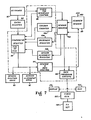
- FIG. 14 a system and a method for positioning a viewer microfiche card for reading is illustrated in which the apparatus comprises a keyboard 176 and an entry register 180 which are the same as similar elements illustrated in FIG. 7.
- the user keys in a desired address and an activation order, the address being deposited in the entry register 180 and the activation order being forwarded to the block 178 for sequence control.
- the clock is illustrated as being connected only to certain components, while clock connections to other components have been omitted for purpose of simplicity.
- the row register 194 via the comparator register 182, determines the vertical and horizontal direction in which the microfiche must be moved in order to bring the selected frame into the viewing position.
- the microfiche moves either vertically or horizontally, never diagonally in this system.
- the tracking comparator 192 is fed by the sensor 188 by way of the sensor register 190 and compares the track position with a standard track position and controls the horizontal and vertical microfiche drives 186 and 184, respectively, to maintain tracking as discussed above so that the sensor extends over all three tracking lines in the particular direction which the microfiche is being driven.
- the sensor register provides an output 198 as the data output, which output may have interposed therein an auxiliary code register 200 which reads the auxiliary codes, such as are illustrated in FIGS. 11 and/or 12.
- the sensor 188 may be a 40 or 60 element sensor of the type discussed above.
- the vertical and horizontal drives 184 and 186, as well as the keyboard 176 and 180 are well known to those skilled in the art, while the elements bounded by the broken line may be a conventional microprocessor, such as the Intel 8080A or the Motorola MC6800P.
- the comparator register 182 includes a ROM or a RAM section for storing the program. In a particular device constructed and utilized we have employed the Motorola MC6800P microprocessor with a RAM section so that it was necessary to feed in the program each time the system was energized.
- the following is an exemplary program for accurately,positioning a viewer microfiche, or more importantly a desired portion of a viewer microfiche, with respect to a viewer. It should be understood by those versed in this art that a similar program, although a simpler program, may be employed in connection with the apparatus of FIG. 7 for accurate alignment of a data row 58 (FIGS. 4-6) in that the scanner microfiche is generally only operated by movement of the sensor (or transport) in a single direction, in addition to correction of skew by the pivoting of the sensor or the transport, and in connection with the additional apparatus of FIG. 14 which relates to reading with the scanner.
- Routine executed upon reaching home on destination frame. Reads all codes at destination, chooses next frame address from array based on user key input. Finally, return to home position on the frame and proceeds to user next frame for movement based on key input on 64 or 65.
- peripheral apparatus is provided for the scanner, which apparatus comprises a scanner control 202 and the sensor apparatus disclosed in FIG. 7, namely the sensor position drive 90, the sensor alignment drive 92, the scanner sensor 98, and the sensor register 102, as well as the auxiliary apparatus used in displaying, recording and transmitting the output data.
- This latter apparatus comprises the LED display 22, the line printer 14, the digital tape recorder 15, and the MODEM unit 16.
- a dealership information terminal is generally illustrated at 10 as comprising a microfiche file 11 which includes master, parts and price microfiche, a viewer 12, a scanner 13, a printer 14, a tape recorder 15, a MODEM unit 16, and his local telephone instrument 17.
- the telephone instrument 17 may be used to connect the terminal by way of the telephone network 18 to a central computer 19 located in a plant which supplies parts to the dealership.
- the printer may advantageously be a line printer, such as the 40 character line printer of Anadex model DP-1000.
- a suitable tape recorder is the digital recorder, known as the SC-1000 Dumb Recorder, manufactured by Seaton Corp.
- the MODEM unit may be a Data COM 302.
- the viewer 12 is illustrated as comprising a viewing screen 20 which is positioned with respect to an optical system (not shown) which includes a microfiche transport which receives the viewer-type microfiche through a slot 21.
- a digital display 22 for example a LED display, is positioned immediately below the viewing screen 20.
- the viewer 12 also comprises a keyboard which includes a four-function calculator unit 23 and a plurality of operational switches 24-33, the purpose of which will become evident from the description below.
- FIG. 2 illustrates a portion of a frame 34 of a viewer microfiche, corresponding to a frame 112 of FIG. 8, which microfiche is a master microfiche
- FIG. 3 illustrates a frame 35, also corresponding to a frame 112 of FIG. 8, of a viewer microfiche which is constructed as a parts fiche.
- the frame 35 is illustrated as comprising one portion 36 which bears graphic information, here in the form of an exploded view of a pump, and another portion 37 which bears alphanumeric information concerning the parts illustrated in the frame portion 36.
- a customer goes to the parts department of a dealership, for example a farm equipment dealership, needing a part for a tractor.
- the customer has the model number and can describe where the part is located on the tractor.
- the parts man matches the machine and model information provided by the customer to the machine and model information on the header of the parts microfiche in the microfiche file 11, extracts the corresponding microfiche from the microfiche file and reads from the header that the parts on this microfiche are also found on the price microfiche il. He then extracts the corresponding price microfiche and inserts the parts microfiche in the slot 21 of the viewer and the price microfiche in the slot 13' of the scanner 13.
- the price microfiche takes the form discussed above with respect to FIGS. 4 and 5, and has a header which identifies the models served by that parts microfiche. There are, of course, fewer price microfiche than parts microfiche, since a single price microfiche carries prices for several models.
- the data itself is in the form of digitized codes readable to the scanner, rather than to the human eye.
- the parts man then presses the HOME button 33 which inputs an address for a home position into the entry register 180 (FIG. 14) to automatically index the microfiche to the first frame.
- the first frame is an index frame which bears alphanumeric information for the parts on that particular microfiche, such as "Dual Pump--Frame 12".
- the parts man then enters the 12 with the numerical keys 23 and presses the ADVANCE key 30..
- the 12 is the address and the key 30 provides the activation.
- the system operates for alignment as discussed above so that frame 12 becomes properly registered and the content thereof appears on the screen 20. In this example, this is the frame illustrated in FIG. 3.
- the parts man checks the part and its location with the customer to determine if the proper part has, indeed, been selected.
- the part 11 indicated at 38 is the desired part and is described with the key number 11 at 39 in the portion 37 of the frame as being the manufacturer's part number W 11852, as seen at 40, and is described at 41 to be a SHAFT- drive (.1).
- the correct part corresponds to the locator number "(1) 01-237".
- the portion (1) of the locator number indicated at 42 corresponds to the price microfiche.
- the locator number has a two-fold function. First of all, within the dealership the locator number can identify a physical location of the part, e.g., the corresponding part bin. Secondly, the locator number portion 43 is the address for the price microfiche.
- the parts man then enters the locator number portion 43 with the keyboard keys 23 and presses the PRICE key 31.
- the scanner transport moves to the addressed column and reads that portion of the column called for by the address,
- the entry from the address register 180 into the comparator register 182 may set up a basis of comparison which instructs the microprocessor and associated circuits to cause the scanner sensor to read only those bits occurring after the sensor scans a predetermined number of bits.
- the scanner control 202 feeds the scanned information into the comparator register 182 via the auxiliary code register 200.
- the comparator register 182 over a similar path back to the scanner control 202, which comprises logic circuits, monitors the data being presented from the scanner sensor 98 to the sensor register 102 so that the information finally lodged in the auxiliary code register is that portion of the scanned line defined by the address of the locator number. Actuation of this process by depression of the key 31 causes the desired information to be output to the display unit 22.
- the manufacturer's part number W 11852 is displayed as a check, as is the price fiche locator number (1) 01-237.
- the asterisk appearing on the display tells the parts man that the dealer has that part in stock.
- the information to the far right-hand side indicates that the desired part has a price of $7.25.
- the locator number in the central portion of the display informs the parts man of the physical location of the part.
- the desired part is retrieved and the parts man copies the information from the display line onto the customer's sales invoice.
- the key 29 activates the line printer 14 which immediately copies the part information, error-free, from the entire display line onto a printer tape. The entry is thereby logged as a part of the day's transactions.
- a # appears as a part of the display to indicate that the locator number is a composite number.
- a single number is selected as the locator and appears on the master microfiche, the price microfiche and on the stop bins.
- the master microfiche Upon selecting the correct master microfiche, he places the same in the viewer slot 21 and presses the HOME key 33. As with the parts microfiche, the master microfiche is addressed and moved to the home frame, generally the first frame.
- the home frame comprises an index or the first page of an index which states that the part numbers in the area under investigation are located at frame 47.
- Cancellations are also readily handled with this PMIC system. If a customer calls later to cancel an order, the parts man can simply bring up the same display on the LED unit 22, depress the CANCEL key 27 and then depress the PRINT key 29. The cancellation activates both the printer 14 and the magnetic tape recorder 15.
- the memory key MM can be used to enter all part locator numbers calling for the same price microfiche and recalled by pressing the IIR key and then the PRICE key to display the line of information.
- the clear entry CE key permits the parts man to recover from a faulty entry, as is common practice with calculator devices, and the RETRACE key 32 permits the parts man to retrace frames step-by-step previously called for up to, for example, 32 frames in that the internal built-in memory is a last in-first out (LIFO) memory.
- LIFO last in-first out
- the parts man will find the printed tape an essential part of his operation in that it carries all transactions identified by the symbols SALE, CHARGE, ORDER, CANCELLATION that was a SALE or a CHARGE or an ORDER or a CANCELLATION.
- the printed tape also carries information entered directly from the keyboard, for example the printing of the customer's invoice number with each transaction.
- the system also allows the parts man to order a particular quantity by calling up the price line, by keying in the desired quantity, depressing the Q key 28, depressing the ORDER key 26 and then the key 29.
- all transactions can be placed on the magnetic tape during the day and then, at the end of the day, extracted type-by- type onto the print tape, by use of optional additional controls associated with the magnetic recorder.
- the printed tape is a permanent record of the day's activity in the parts department, as well as a record of the day's orders contained on the magnetic tape.
- the parts man is ready to submit orders to the computer 19 at the factory, he places a telephone call with the conventional telephone instrument 17 and dials in his assigned identification code. He is then interfaced with the computer 19 which will accept the data from the magnetic tape unit 15. He then places the telephone hand set on the MODEM unit 16 and activates playing of the magnetic tape through the MODEM unit 16, the telephone 17 and the telephone network 18 to the computer 19.
- the PMIC system described has serviced six of the seven critical areas previously stressed including quick access to parts identification and price, fast retrieval from storage bins, complete records, daily ordering and frequent fulfillment.
- the key. is the microfiche as a data base, which is distributed at the remote locations, on safe, read-only microfiche media.
- a PMIC system requires information that is both accurate and current--current enough for the application, yet costing no more than absolutely necessary.
- the price microfiche plays a particularly special communications role in providing this information up-date feature, both accurately and economically.
- a troublesome particularly disadvantageous drawback to the use of microfilm verses paper was the inability to correct errors regarding price or part information.
- a parts man became aware of an error he could not make a note of it on microfilm as he could on paper.
- the cooperable COM-generated digital microfiche having high-density digitized information, errors are quickly and economically rectified.
- the price microfiche are replaced at responsible intervals and each may contain a special section which holds inventory up-date information.
- a new price microfiche he may place the same in the scanner and press a predetermined address, for example, 30-300 on the keyboard and then the PRICE key.
- the title line of a list of special messages appears on the display. He may, at this point, elect to read these messages one- by-one by pressing the PRICE key each time. Or, he may elect to use the PRINT key and obtain a print out of all the messages.
- the price microfiche also supplies the corrective information required for a part: substitutions, parts that have become obsolete, new interchangeable parts, replacements, and errors.
- the display line appears, but special information on the digitized price microfiche energizes, in an automatically flashing manner, a lamp below the PRICE key. This signals that there is corrective information on this part. By pressing the PRICE key, the correct information will appear on the line; in this case, a substituted part number.
- the PMIC system disclosed herein is a totally integrated communications system which is readily expandable in function to economically meet the data base and random access requirements of business, industry, education,military and government.
- bank account signature cards may be placed on viewer-type microfiche with the account number serving as an address of the frame on which that signature will appear.
- account numbers would be grouped and a decoder included to define a common address for a plurality of signatures. Keying in of the account number would then cause the viewer to function as before so that the desired signature, along with signatures of the same frame, will be brought into view for checking the same against the signature on a check, withdrawal slip or the like.
- FIG. 1B illustrates the scanner 13 connected to the keyboard 82 of FIG. 7 and receiving a digitized microfiche 50 of the type illustrated in FIG. 5, for feeding information to a display unit 22.
- the circuit is shown adapted for display of the digitized information carried by the scanner-type microfiche on a TV set 101, the information being fed from the data processing circuits 96 to the TV set 101 by way of a video display generator 103.
- the video display generator may be constituted by, for example, the video display generator S68047 manufactured by American Microsystems, Inc.
- a computer such as a home computer is generally illustrated as comprising a program section including a RAM 105 which is fed by a scanner 13 which receives the program on a digital microfiche 54' of the type illustrated in FIG. 6.
- a scanner 13 which receives the program on a digital microfiche 54' of the type illustrated in FIG. 6.
- the keyboard and entry register would include a permanent sequential address for sequentially stepping the scanner to output the program to the RAM 105.
- a more simple control circuit may be included in the scanner in place of the microprocessor to merely step the scanner through its sequence of operations.
- the embodiment of FIG. 5 may also be used as a RAM and accessed by addressing of the scanner by the computer.
Landscapes
- Physics & Mathematics (AREA)
- General Physics & Mathematics (AREA)
- Engineering & Computer Science (AREA)
- Theoretical Computer Science (AREA)
- Information Retrieval, Db Structures And Fs Structures Therefor (AREA)
- Credit Cards Or The Like (AREA)
Applications Claiming Priority (4)
| Application Number | Priority Date | Filing Date | Title |
|---|---|---|---|
| US05/922,798 US4213040A (en) | 1978-07-07 | 1978-07-07 | Digital microfiche and apparatus for accurately positioning the microfiche |
| US956426 | 1978-10-31 | ||
| US05/956,426 US4254329A (en) | 1978-10-31 | 1978-10-31 | Microfiche information retrieval and control system utilizing machine readable microfiche and visually readable microfiche |
| US922798 | 1992-07-31 |
Publications (1)
| Publication Number | Publication Date |
|---|---|
| EP0007660A1 true EP0007660A1 (de) | 1980-02-06 |
Family
ID=27129850
Family Applications (1)
| Application Number | Title | Priority Date | Filing Date |
|---|---|---|---|
| EP79200373A Withdrawn EP0007660A1 (de) | 1978-07-07 | 1979-07-06 | System zum Auffinden und Bearbeiten von auf Microfiches festgelegten Daten, das maschinell und visuell lesbare Microfiches verwendet |
Country Status (4)
| Country | Link |
|---|---|
| EP (1) | EP0007660A1 (de) |
| AU (1) | AU4872279A (de) |
| CA (1) | CA1152610A (de) |
| WO (1) | WO1980000200A1 (de) |
Cited By (10)
| Publication number | Priority date | Publication date | Assignee | Title |
|---|---|---|---|---|
| FR2503901A1 (fr) * | 1981-04-10 | 1982-10-15 | Piaton Alain | Reseau telematique de consultation d'informations a distance |
| EP0146257A1 (de) * | 1983-11-08 | 1985-06-26 | Storage Research Pty. Ltd. | Maschinell lesbare Marken für kartesianische Informationsaufzeichnungsmedien |
| FR2594968A1 (fr) * | 1986-02-21 | 1987-08-28 | Alsthom | Dispositif d'assistance aux operations de montage d'un assemblage avec autocontrole |
| US4695991A (en) * | 1980-12-09 | 1987-09-22 | Storage Research Pty. Ltd. | Reading information stored in multiple frame format |
| GB2191611A (en) * | 1986-05-28 | 1987-12-16 | John Adrian Pickering | A man-computer data input technique |
| EP0257595A3 (en) * | 1986-08-22 | 1988-07-20 | Csk Corporation | Optical recording medium |
| EP0383237A3 (de) * | 1989-02-13 | 1992-06-10 | Omron Corporation | Aufnahme-/Wiedergabegerät für optische Karte |
| EP0551923A3 (en) * | 1992-01-17 | 1996-01-03 | Eastman Kodak Co | Consensus sync" data-sampling systems and methods |
| EP0717398A3 (de) * | 1994-12-16 | 1996-07-10 | Olympus Optical Co | |
| EP0702369A3 (de) * | 1994-09-19 | 1999-02-24 | Olympus Optical Co., Ltd. | Informationsaufzeichnungsmedium und Informationswiedergabegerät |
Citations (6)
| Publication number | Priority date | Publication date | Assignee | Title |
|---|---|---|---|---|
| DE2046860A1 (de) * | 1969-09-24 | 1971-07-15 | Iria | Anlage und Verfahren zur Auswertung einer Mikrokopie Dokumentation |
| DE2151125A1 (de) * | 1971-10-12 | 1973-04-26 | Adressorgraph Multigraph Corp | Datentraegerelement |
| DE2533938A1 (de) * | 1974-07-30 | 1976-02-26 | Sharp Kk | Mikrofilmdokumentationsspeicherung und system zur erneuerung des informationsstandes |
| US4086469A (en) * | 1974-11-02 | 1978-04-25 | Minolta Camera K.K. | Microfiche reader control means |
| DE2647831A1 (de) * | 1976-10-22 | 1978-04-27 | Emac Elektro Maschinen Und App | Elektronisches mikrofichelese- und auswertegeraet |
| US4097846A (en) * | 1977-04-08 | 1978-06-27 | Energy Conversion Devices, Inc. | Data storage and retrieval system |
Family Cites Families (12)
| Publication number | Priority date | Publication date | Assignee | Title |
|---|---|---|---|---|
| US2594358A (en) * | 1950-04-24 | 1952-04-29 | Us Agriculture | System and apparatus for selective photographing |
| US3186111A (en) * | 1961-12-06 | 1965-06-01 | Reed C Lawlor | "peek-a-boo" retrieval system |
| US3484588A (en) * | 1964-10-09 | 1969-12-16 | Jonker Business Machines Inc | Plane type line scanner for universal information system |
| US3371324A (en) * | 1964-11-25 | 1968-02-27 | Sinoto Nori | Light-modulating information storage and retrieval system and method |
| US3555248A (en) * | 1968-06-28 | 1971-01-12 | Image Systems Inc | Card-type storage item and clip |
| DE1774818B1 (de) * | 1968-09-13 | 1971-07-01 | Minox Gmbh | Vorrichtung zur datenaufbereitung |
| US3660641A (en) * | 1969-10-30 | 1972-05-02 | Simcom Corp | Coded data storage medium |
| BE792538A (fr) * | 1971-12-09 | 1973-03-30 | Comprehensive Health Services | Procede et dispositif d'enregistrement, de traitement et de presentation d'informations concernant une structure physique |
| US3935427A (en) * | 1973-12-26 | 1976-01-27 | Sun Electric Corporation | Car diagnosis system |
| US4027142A (en) * | 1974-03-06 | 1977-05-31 | Recognition Equipment Incorporated | Automated processing of financial documents |
| US4053844A (en) * | 1975-09-26 | 1977-10-11 | Moise N. Hamaoui | Card-reader integrated circuit tester |
| US4110020A (en) * | 1976-08-03 | 1978-08-29 | Bell & Howell Company | Electronically controlled microfilm photographic image utilization device |
-
1979
- 1979-06-28 WO PCT/US1979/000457 patent/WO1980000200A1/en not_active Ceased
- 1979-07-06 CA CA000331290A patent/CA1152610A/en not_active Expired
- 1979-07-06 AU AU48722/79A patent/AU4872279A/en not_active Abandoned
- 1979-07-06 EP EP79200373A patent/EP0007660A1/de not_active Withdrawn
Patent Citations (6)
| Publication number | Priority date | Publication date | Assignee | Title |
|---|---|---|---|---|
| DE2046860A1 (de) * | 1969-09-24 | 1971-07-15 | Iria | Anlage und Verfahren zur Auswertung einer Mikrokopie Dokumentation |
| DE2151125A1 (de) * | 1971-10-12 | 1973-04-26 | Adressorgraph Multigraph Corp | Datentraegerelement |
| DE2533938A1 (de) * | 1974-07-30 | 1976-02-26 | Sharp Kk | Mikrofilmdokumentationsspeicherung und system zur erneuerung des informationsstandes |
| US4086469A (en) * | 1974-11-02 | 1978-04-25 | Minolta Camera K.K. | Microfiche reader control means |
| DE2647831A1 (de) * | 1976-10-22 | 1978-04-27 | Emac Elektro Maschinen Und App | Elektronisches mikrofichelese- und auswertegeraet |
| US4097846A (en) * | 1977-04-08 | 1978-06-27 | Energy Conversion Devices, Inc. | Data storage and retrieval system |
Cited By (19)
| Publication number | Priority date | Publication date | Assignee | Title |
|---|---|---|---|---|
| US4695991A (en) * | 1980-12-09 | 1987-09-22 | Storage Research Pty. Ltd. | Reading information stored in multiple frame format |
| US4947383A (en) * | 1980-12-09 | 1990-08-07 | Hudson Allen Limited | Machine readable markers for cartesian information storage media |
| EP0063080A1 (de) * | 1981-04-10 | 1982-10-20 | Alain Nicolas Piaton | Verwendung eines Neztwerkes zum Fernabfragen von Informationen |
| FR2503901A1 (fr) * | 1981-04-10 | 1982-10-15 | Piaton Alain | Reseau telematique de consultation d'informations a distance |
| EP0146257A1 (de) * | 1983-11-08 | 1985-06-26 | Storage Research Pty. Ltd. | Maschinell lesbare Marken für kartesianische Informationsaufzeichnungsmedien |
| EP0236808A1 (de) * | 1986-02-21 | 1987-09-16 | Gec Alsthom Sa | Vorrichtung zur Unterstützung der Erstellung eines Zusammenbauprogramms mit Selbstüberwachung |
| FR2594968A1 (fr) * | 1986-02-21 | 1987-08-28 | Alsthom | Dispositif d'assistance aux operations de montage d'un assemblage avec autocontrole |
| GB2191611A (en) * | 1986-05-28 | 1987-12-16 | John Adrian Pickering | A man-computer data input technique |
| EP0257595A3 (en) * | 1986-08-22 | 1988-07-20 | Csk Corporation | Optical recording medium |
| US5559773A (en) * | 1989-02-13 | 1996-09-24 | Omron Corporation | Self correcting recording reproducing apparatus for an optical card |
| EP0383237A3 (de) * | 1989-02-13 | 1992-06-10 | Omron Corporation | Aufnahme-/Wiedergabegerät für optische Karte |
| EP0551923A3 (en) * | 1992-01-17 | 1996-01-03 | Eastman Kodak Co | Consensus sync" data-sampling systems and methods |
| EP0702369A3 (de) * | 1994-09-19 | 1999-02-24 | Olympus Optical Co., Ltd. | Informationsaufzeichnungsmedium und Informationswiedergabegerät |
| US5999665A (en) * | 1994-09-19 | 1999-12-07 | Olympus Optical Co., Ltd. | Information reproducing device having error informing means |
| US6148121A (en) * | 1994-09-19 | 2000-11-14 | Olympus Optical Co., Ltd. | Information reproducing device having error informing means |
| EP0717398A3 (de) * | 1994-12-16 | 1996-07-10 | Olympus Optical Co | |
| US5866895A (en) * | 1994-12-16 | 1999-02-02 | Olympus Optical Co., Ltd. | Information recording medium and information reproduction system |
| US6116507A (en) * | 1994-12-16 | 2000-09-12 | Olympus Optical Co., Ltd. | Information reproduction system for reproducing multimedia information recorded in the form of an optically readable dot code pattern wherein the optical readable dot code comprises address dots |
| US6131807A (en) * | 1994-12-16 | 2000-10-17 | Olympus Optical Co., Ltd. | Information recording medium and information reproduction system |
Also Published As
| Publication number | Publication date |
|---|---|
| CA1152610A (en) | 1983-08-23 |
| AU4872279A (en) | 1980-01-10 |
| WO1980000200A1 (en) | 1980-02-07 |
Similar Documents
| Publication | Publication Date | Title |
|---|---|---|
| US4213040A (en) | Digital microfiche and apparatus for accurately positioning the microfiche | |
| EP0114723B1 (de) | Dokumentenausgabevorrichtung | |
| US5019694A (en) | Overhead scanning terminal | |
| US4423316A (en) | Automatic banking system | |
| AU659136B2 (en) | Apparatus and method for generating a receipt | |
| US4608488A (en) | Document issuing apparatus | |
| US5019697A (en) | Data collection system using memory card | |
| US5469241A (en) | Microfilm camera | |
| US3734286A (en) | Article handling apparatus | |
| US6994252B2 (en) | Combination library patron-supervisor self check-in/out workstation | |
| US5362949A (en) | Packing house control system | |
| EP0443419B1 (de) | Einrichtung für die Ermittlung des Verkaufspreises von Waren | |
| EP0007660A1 (de) | System zum Auffinden und Bearbeiten von auf Microfiches festgelegten Daten, das maschinell und visuell lesbare Microfiches verwendet | |
| GB2252433A (en) | Questionnaire system | |
| US3585597A (en) | Information storage and retrieval system | |
| US3932036A (en) | Card printer | |
| US3558859A (en) | Automatic reading system for record media having encoded data | |
| US3573436A (en) | Method and apparatus for reading tickets, and ticket for use therewith | |
| US3536395A (en) | Transaction recording apparatus and system | |
| US5990915A (en) | Time recorder with code reader and data storage | |
| US3260999A (en) | Electronic selector system | |
| US4310751A (en) | Microfilm indexing machine | |
| JPH06187518A (ja) | 総会運営システム管理装置及び総会運営システム管理方法 | |
| US3520602A (en) | Graphic display device | |
| WO2024144476A1 (en) | A field automation system |
Legal Events
| Date | Code | Title | Description |
|---|---|---|---|
| PUAI | Public reference made under article 153(3) epc to a published international application that has entered the european phase |
Free format text: ORIGINAL CODE: 0009012 |
|
| AK | Designated contracting states |
Designated state(s): AT BE CH DE FR GB IT LU NL SE |
|
| 17P | Request for examination filed | ||
| R17P | Request for examination filed (corrected) |
Effective date: 19800805 |
|
| STAA | Information on the status of an ep patent application or granted ep patent |
Free format text: STATUS: THE APPLICATION IS DEEMED TO BE WITHDRAWN |
|
| 18D | Application deemed to be withdrawn |
Effective date: 19830610 |
|
| RIN1 | Information on inventor provided before grant (corrected) |
Inventor name: GOKEY, PHILLIPS E. Inventor name: TERRY, ANGEL F. Inventor name: SEDERHOLM, EMMA LOU Inventor name: HURLBUT, DONOVAN W. |