EP0007773B1 - Halte- und Sperrsystem eines Ohrrings für ein durchstochenes Ohr - Google Patents
Halte- und Sperrsystem eines Ohrrings für ein durchstochenes Ohr Download PDFInfo
- Publication number
- EP0007773B1 EP0007773B1 EP19790301425 EP79301425A EP0007773B1 EP 0007773 B1 EP0007773 B1 EP 0007773B1 EP 19790301425 EP19790301425 EP 19790301425 EP 79301425 A EP79301425 A EP 79301425A EP 0007773 B1 EP0007773 B1 EP 0007773B1
- Authority
- EP
- European Patent Office
- Prior art keywords
- shaft
- locking bar
- locking
- holding system
- pierced
- Prior art date
- Legal status (The legal status is an assumption and is not a legal conclusion. Google has not performed a legal analysis and makes no representation as to the accuracy of the status listed.)
- Expired
Links
- 230000002093 peripheral effect Effects 0.000 claims description 2
- 230000004323 axial length Effects 0.000 claims 1
- 238000010276 construction Methods 0.000 description 26
- 238000004519 manufacturing process Methods 0.000 description 3
- 230000008901 benefit Effects 0.000 description 2
- 210000000624 ear auricle Anatomy 0.000 description 2
- 210000005069 ears Anatomy 0.000 description 2
- 238000009957 hemming Methods 0.000 description 2
- 238000003780 insertion Methods 0.000 description 2
- 230000037431 insertion Effects 0.000 description 2
- 238000000034 method Methods 0.000 description 2
- 239000007787 solid Substances 0.000 description 2
- 239000004677 Nylon Substances 0.000 description 1
- 238000010420 art technique Methods 0.000 description 1
- 230000008859 change Effects 0.000 description 1
- 230000009133 cooperative interaction Effects 0.000 description 1
- 230000007812 deficiency Effects 0.000 description 1
- 230000006870 function Effects 0.000 description 1
- 239000010437 gem Substances 0.000 description 1
- 230000001939 inductive effect Effects 0.000 description 1
- 238000003754 machining Methods 0.000 description 1
- 230000013011 mating Effects 0.000 description 1
- 229920001778 nylon Polymers 0.000 description 1
- 230000008569 process Effects 0.000 description 1
- 230000002195 synergetic effect Effects 0.000 description 1
- 230000009044 synergistic interaction Effects 0.000 description 1
Images
Classifications
-
- A—HUMAN NECESSITIES
- A44—HABERDASHERY; JEWELLERY
- A44C—PERSONAL ADORNMENTS, e.g. JEWELLERY; COINS
- A44C7/00—Ear-rings; Devices for piercing the ear-lobes
Definitions
- This invention relates to pierced-ear earrings and more particularly to a one-piece pierced-ear earring construction which is quickly, securely and easily locked in position.
- the clip-on type earring is the clip-on type earring.
- the second category of earrings is the pierced ear type, and represents earring type to which this application is directed.
- pierced earrings have been used at least since the turn of the century, little change or innovative variations has been realized in the systems used to securely mount the earring in the pierced ear of the user.
- the typical configuration found in pierced earrings for the last hundred years is a solid, elongated shaft or stem, to which the particular decorative portion of the earring is secured, with a locking mount or a holding nut slidably engagable along the elongated shaft for attachment thereto.
- various alternative constructions for the holding nut of this common type of pierced earring has been developed through the years, all of these holding nuts suffer from common deficiencies.
- Driscoll '033 a one-piece earring holding shaft is disclosed, but without the use of any pivoting or moving portions formed thereon. Instead, Driscoll '033 teaches a one-piece earring shaft construction extending from the ornament, and incorporating a combination of angular bends.
- Driscoll '033 does teach a system which eliminates the difficulties presently encountered with lock nuts, the D/7seo// '033 system requires the user to manipulate the earring in a variety of alternative positions, to insert the elongated peculiarly convoluted shaft into position, with the convoluted portions thereof performing the holding function. Due to the high degree of dexterity an unnatural manipulated movements required in order to completely insert the construction taught by Driscoll'033, this construction has not received popular acceptance.
- Driscoll '034 another holding system is taught for a pierced earring wherein two or more pendants are required and are supported by nylon filaments connected to a cylindrically- shaped toggle.
- the independent toggle is inserted through the pierced ear and, when one of the pendants is pulled, assumes a locking position.
- the pendant connected to the terminating end of the toggle is pulled, aligning the toggle for removal through the pierced ear.
- this system is extremely limited in that it requires the use of flexible filaments which are positioned in the ear when the earring is worn. This is generally undesirable and unwanted by users.
- the dual-pendant construction which is required to properly operate the toggle is extremely limiting and prevents a pierced earring construction which will accommodate the majority of present-day pierced earring designs.
- Hemming A very early proposal of earring is disclosed in British Patent No. 1440 of 1884 (Hemming).
- the Hemming patent discloses a stud earring comprising a wire one end of which is connected to the stud end and the other end has a gap formed therein for a pivoted locking bar.
- that proposal requires machining which complicates manufacture.
- Another object of the present invention is to provide a pierced earring holding system having the characteristic features defined above which can be employed on all pierced earring designs regardless of the size or shape or construction of the visible ornamentation.
- an integral, locking and holding system for pierced-ear earrings comprising:
- the pierced earring holding system of the present invention is easily inserted in the pierced ear of the user, in the conventional fashion, with the pivotal portion in its first position.
- the entire shaft comprises a substantially straight elongated member, which is quickly and easily inserted into the pierced ear of the user without any difficulty being encountered by the user.
- the pivotal, terminating end portion of the shaft is quickly and easily pivoted into the second position, forming a locking arm which prevents egress of the supporting shaft from the pierced ear.
- the self-locking shaft of the present invention assures complete locking engagement in the pierced ear of the user, without requiring any unconventional or difficult manipulative effort by the user, while also eliminating the need for employing any independent piece which can be dislodged or lost during use.
- the invention accordingly comprises an article of manufacture possessing the features, properties, and the relation of elements which will be exemplified in the article hereinafter described, and the scope of the invention will be indicated in the claims.
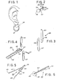
- a pierced earring holding system 20 of the present invention is shown mounted to a conventional earring ornamental design structure 21, for exemplary purposes only, design structure 21 is shown as a ring.
- design structure 21 is shown as a ring.
- earring holding system 20 and its associated ring 21 is shown mounted in its securely engaged position in the pierced ear of a user.
- locking and holding system 20 comprises a substantially straight and elongated shaft 52, with a locking bar 53 pivotally mounted at the distal end of shaft 52, using a pivot pin 54.
- shaft 52 comprises two individual portions 57 and 59 which have been intertwined to form a continuous, twisted, rope-like configuration, while also achieving a substantially straight shaft 52.
- the terminating end of twisted portion 57 and the terminating end of twisted portion 59 are interengaged by pivot pin 54, with locking bar 53 mounted therebetween.
- the locking bar 53 is preferably pivotally mounted near one of its ends, providing a secure locking structure.
- locking bar 53 is not able to rotate through 360°.
- locking bar 53 can be mounted between the terminating ends of portions 57 and 59 with locking bar 53 pivotally engaged substantially at its midpoint.
- portions 57 and 59 must be removed from intertwined secure interengagement at a position earlier than is shown in Figure 2, in order to provide a recess area 55 therebetween which will accommodate the greater length of locking bar 53.
- the particular ornament 58 shown in this embodiment comprises a pearl, with portions 57 and 59 forming shaft 52 being directly mounted at their proximal end to a pearl holding and receiving cup 56.
- Pierced earring holder system 20 can be employed with any pierced earring design, regardless of its physical structure, by merely affixing holding system 20 to the particular design structure using present state of the art techniques employed for the conventional elongated straight shafts requiring locking nuts.
- the quick, easy and efficient insertion and locked engagement of the pierced earring holding system 20 of the present invention is achieved by pivoting the locking bar into its aligned position and inserting it into the channel formed in the user's earlobe, with ease and simplicity with which pierced earring wearers have become proficient.
- the shaft of the holding system 20 is located within channel and the user can easily pivot the locking bar from its axially aligned position into its locking position, wherein the longitudinal axis of the locking bar is substantially perpendicular to the axis of shaft.
- the earring is securely engaged and locked in the pierced ear of the user, completely eliminating fear of dislocation, dislodgement, or loss of any separate, removable locking portion.
- This securely engaged lock position is represented in Figure 1.
- the cuff link structure requires a biasing system since a positive force is necessary to resist the various rotation-inducing forces acting upon the locking member during use of the cuff link. If any of these forces were successful, the cuff link could become dislodged from the shirt and possibly lost.
- biasing systems are not required due to the synergistic interaction of this embodiment of the locking and holding system of the present invention with the user'sear.
- the user elongates her ear when the earring is being inserted, by pulling downward on the ear lobe. This downward force causes the channel through the lobe to widen while also producing an overall thinning of ear.
- the locking bar While ear is in this elongated and thinned configuration, the locking bar is pivoted from its first, ear inserting aligned position to its second, locked position. Once the locking bar has been pivoted to its locked position, the downward force on the ear is removed, allowing the ear to return to its original length and thickness.
- elongated shaft comprises an overall diameter of about one millimeter.
- the overall length of the shaft, which includes the juxtaposed facing arms would preferably be about 7/16 inches long.
- the locking bar Since the locking bar is pivotally engaged at the distal end of shaft and has a position wherein a portion of the locking bar is coaxially aligned with the shaft, the locking bar must have an overall thickness less than the one millimeter diameter of the shaft. Preferably, the locking bar comprises a thickness of 0.5 to 0.75 millimeters.
- locking bar may comprise a variety of lengths, it has been found that an overall length of about 5/ 16 inches assures secure locked engagement of pierced earring locking system 20, while also being easily handled and manipulated by the user.
- locking and holding system 20 comprises a locking bar 63 having two separate, independently pivotable sections 66 and 67.
- sections 66 and 67 are split along the longitudinal axis of locking bar 63, forming two substantially equally sized and shaped members.
- sections 66 are identical and can be manufactured from the same mould.
- This embodiment allows locking bar 63 to be pivotally engaged near one of its terminating ends, with sections 66 and 67 being arcuately pivoted about the pivot axis in opposite directions.
- pivotable locking bar 63 achieves a position with its longitudinal axis substantially perpendicular to the central axis of the shaft to which it is joined with locking bar 63 having substantially equal length segments extending from both sides of the shaft.
- this construction achieves both the (1) enhanced structural integrity and reliability of the small, finely constructed members by eliminating unnecessary elongated recesses extending a substantial distance along a particular shaft, and (2) added security and locked engagement by having substantially equal length segments of the locking bar extending from opposite sides of the elongated shaft when mounted in a pierced ear.
- locking bar sections 66 and 67 also preferably incorporate at least one. small boss or post 68 formed on the outer surface of each locking section 66 and 67 which may engage in recess areas or cutouts formed in the outer peripheral surface of the associated shaft.
- this embodiment of locking and holding system 20 assures the biased, locked engagement of sections 66 and 67 of locking bar 63 in either of the two alternative positions, when so desired.
- split locking bar construction discussed above can be manufactured in a variety of ways, one of which would be to eliminate posts 68 and associated recesses, it has been found that the construction defined above for locking bar 63 with posts 68 in the preferred construction. However, as would be obvious to one skilled in the art, a variety of alternative locking systems can be employed without departure from the scope of the present invention.
- FIG 4 an alternative embodiment of pierced earring holding system 20 of the present invention is shown.
- the integrally twisted rope configuration for shaft 52 defined with reference to Figure 2 is employed in combination with locking bar sections 66 and 67.
- elongated straight shaft 52 comprises two independent elongated portions 57 and 59, which are integrally intertwined to form a substantially straight, elongated shaft 52.
- Locking bar sections 66 and 67 are mounted at the terminating ends of portions 57 and 59 using pivot pin 54. If desired, biasing locking and holding posts 68 and recesses can be incorporated into this construction in order to provide the secure biased and locked positions for locking bar sections 66 and 67.
- shaft 52 can be constructed to allow locking bar sections 66 and 67 to rotate 360° about the axis defined by pivot pin 54. This can be easily achieved by providing a recess 55 which extends from the distal end of shaft 52 forwardly a sufficient distance to accommodate the entire length of sections 66 and 67.
- this construction can be made, if so desired, the construction shown in Figure 4 is preferred, since it optimizes the integral contact between portions 57 and 59, reducing the length over which these two portions are not in integral, intertwined contact.
- locking and holding system 20 incorporates locking bar 23 which is pivotally mounted on a single elongated wire member 81 substantially at the midpoint of elongated wire 81.
- the substantially straight elongated shaft 82 shown in Figure 6, is formed from the single elongated wire 81 by first installing locking bar 23 on wire 81 by inserting wire 81 through hole 84 which defines the pivot axis of locking bar 23. Then, wire 81 is bent about a portion of locking bar 23 to form two substantially equal length, parallel wire segments 83 with the two terminating ends 85 of segments 83 of wire 81 in juxtaposed spaced relationship to each other. In Figure 5, wire 81 is shown with substantially equal length segments 83 having been formed but not completely bent into their substantially parallel configuration.
- Segments 83 are then intertwiningly twisted to form the intertwined, twisted rope-like elongated shaft 82 shown in Figure 6. It has been found that this construction provides a quick and easy assembly procedure while also providing an extremely sturdy, well constructed embodiment for locking and holding system 20.
- locking bar 23 pivots about a portion of wire 81, thereby eliminating the necessity for use of a separate pivot pin. Furthermore, locking bar 23, as shown in Figure 6, is mounted in a manner which allows complete rotation of locking bar 23 about its pivot axis without affecting the inherent strength or rigidity of shaft 82.
- locking bar 23 could be mounted near one of its ends with shaft 82 being formed with the locking bar capable of either limited pivoting or complete rotation about its axis.
- This embodiment achieves a unitary, solid construction, wherein the locking and holding is quickly and inexpensively manufactured with a minimum of parts and with minimum ease and efficiency, while also providing a locking and holding system having no member which can become dislodged, loosened, or in any way separated and lost. Furthermore, as discussed above, this embodiment cooperated with the ear to prevent unwanted rotation of locking bar 23 when mounted in the user's ear. This cooperation is important, since a biasing system could not be efficiently introduced into this embodiment.
Landscapes
- Adornments (AREA)
Claims (5)
dadurch gekennzeichnet, daß der Stab zwei Abschnitte (57, 59; 83) umfaßt, die sich in verdrehter, miteinander verschlungener Verbindung über im wesentlichen ihre gesamten Längen befinden, wobei die zwei Abschnitte an ihren distalen Enden voneinander getrennt sind, um einen Aufnahmebereich (55) zum In-Eingriff-Kommen mit dem Sperrstift zu bilden.
Applications Claiming Priority (2)
| Application Number | Priority Date | Filing Date | Title |
|---|---|---|---|
| US92694678A | 1978-07-20 | 1978-07-20 | |
| US926946 | 1978-07-20 |
Publications (2)
| Publication Number | Publication Date |
|---|---|
| EP0007773A1 EP0007773A1 (de) | 1980-02-06 |
| EP0007773B1 true EP0007773B1 (de) | 1985-10-09 |
Family
ID=25453933
Family Applications (1)
| Application Number | Title | Priority Date | Filing Date |
|---|---|---|---|
| EP19790301425 Expired EP0007773B1 (de) | 1978-07-20 | 1979-07-18 | Halte- und Sperrsystem eines Ohrrings für ein durchstochenes Ohr |
Country Status (2)
| Country | Link |
|---|---|
| EP (1) | EP0007773B1 (de) |
| DE (1) | DE2967528D1 (de) |
Families Citing this family (6)
| Publication number | Priority date | Publication date | Assignee | Title |
|---|---|---|---|---|
| DE3267818D1 (en) * | 1982-03-31 | 1986-01-16 | Andra Jewels Ltd | Earfittings for earrings |
| US4468936A (en) * | 1983-09-22 | 1984-09-04 | Andra Jewels Limited | Earring earfitting with primary and secondary locking means |
| IL72913A0 (en) * | 1984-01-05 | 1984-12-31 | Certified Manufacturing Techno | Post for earring |
| JPS62185517U (de) * | 1986-05-16 | 1987-11-25 | ||
| FR2881032B1 (fr) * | 2005-01-27 | 2007-03-30 | Assi Daniel Abou | Systeme de clous d'oreilles ou piercings |
| US9764433B2 (en) | 2012-10-25 | 2017-09-19 | Stephanie GIORLANDO | Earring for pierced ears |
Family Cites Families (6)
| Publication number | Priority date | Publication date | Assignee | Title |
|---|---|---|---|---|
| DE31030C (de) * | JOS. schwinger in Stuttgart | Befestigung von Ohrknöpfchen | ||
| FR732726A (fr) * | 1931-03-07 | 1932-09-24 | Bouton de col perfectionné, combiné avec fixe-cravate | |
| US2148183A (en) * | 1935-07-16 | 1939-02-21 | Swank Products Inc | Cuff link |
| US2544893A (en) * | 1947-12-30 | 1951-03-13 | Ballou & Co B A | Cuff link with movable head |
| FR1157599A (fr) * | 1955-09-22 | 1958-05-30 | Silver Bond Street Ltd E | Bouton de manchettes |
| US4129998A (en) * | 1977-06-07 | 1978-12-19 | Ferro Novelty Company, Inc. | Earring |
-
1979
- 1979-07-18 DE DE7979301425T patent/DE2967528D1/de not_active Expired
- 1979-07-18 EP EP19790301425 patent/EP0007773B1/de not_active Expired
Also Published As
| Publication number | Publication date |
|---|---|
| EP0007773A1 (de) | 1980-02-06 |
| DE2967528D1 (en) | 1985-11-14 |
Similar Documents
| Publication | Publication Date | Title |
|---|---|---|
| US4543804A (en) | Pierced earring locking and holding system | |
| US4249393A (en) | Earring or similar article | |
| US4741179A (en) | Multi-post earring structure for pierced ears | |
| US4377078A (en) | Chain and end attachment means | |
| US4291551A (en) | Combination earring and finger ring | |
| US5433088A (en) | Snap-on earring clasp | |
| EP0007773A1 (de) | Halte- und Sperrsystem eines Ohrrings für ein durchstochenes Ohr | |
| JPH0725046Y2 (ja) | 交換可能なコンポーネント要素を備えた宝飾具 | |
| US5678282A (en) | Jewelry clasp | |
| US6055802A (en) | Fishhook jewelry | |
| EP1344468B1 (de) | Schmuckstück | |
| US20020013598A1 (en) | Body piercing decoration system | |
| CA2012940A1 (en) | Combined bracelet and pendant | |
| EP4349207B1 (de) | Ornament | |
| US5097681A (en) | Pierced earring with integral locking mechanism | |
| US4998330A (en) | Jewelry closure device | |
| US2427479A (en) | Earring and the like | |
| KR200275820Y1 (ko) | 장신용 줄 연결고리의 착탈구조 | |
| KR200320834Y1 (ko) | 귀걸이의 체결구조 | |
| KR200331806Y1 (ko) | 귀금속 장신구의 체결구조 | |
| US4065940A (en) | Toe ring base and ornamental toe ring | |
| US20230218050A1 (en) | Pierced earring locking and holding system | |
| JP2001061519A (ja) | 耳飾り | |
| US9010146B1 (en) | Wearable decorative articles | |
| KR200233862Y1 (ko) | 장신구 |
Legal Events
| Date | Code | Title | Description |
|---|---|---|---|
| PUAI | Public reference made under article 153(3) epc to a published international application that has entered the european phase |
Free format text: ORIGINAL CODE: 0009012 |
|
| AK | Designated contracting states |
Designated state(s): CH DE FR GB IT |
|
| 17P | Request for examination filed | ||
| 18R | Application refused |
Effective date: 19841007 |
|
| D18R | Application refused (deleted) | ||
| ITF | It: translation for a ep patent filed | ||
| GRAA | (expected) grant |
Free format text: ORIGINAL CODE: 0009210 |
|
| AK | Designated contracting states |
Designated state(s): CH DE FR GB IT |
|
| REF | Corresponds to: |
Ref document number: 2967528 Country of ref document: DE Date of ref document: 19851114 |
|
| ET | Fr: translation filed | ||
| PLBE | No opposition filed within time limit |
Free format text: ORIGINAL CODE: 0009261 |
|
| STAA | Information on the status of an ep patent application or granted ep patent |
Free format text: STATUS: NO OPPOSITION FILED WITHIN TIME LIMIT |
|
| 26N | No opposition filed | ||
| PG25 | Lapsed in a contracting state [announced via postgrant information from national office to epo] |
Ref country code: CH Effective date: 19870731 |
|
| PG25 | Lapsed in a contracting state [announced via postgrant information from national office to epo] |
Ref country code: FR Free format text: LAPSE BECAUSE OF NON-PAYMENT OF DUE FEES Effective date: 19880331 |
|
| REG | Reference to a national code |
Ref country code: CH Ref legal event code: PL |
|
| REG | Reference to a national code |
Ref country code: FR Ref legal event code: ST |
|
| PG25 | Lapsed in a contracting state [announced via postgrant information from national office to epo] |
Ref country code: GB Effective date: 19880718 |
|
| GBPC | Gb: european patent ceased through non-payment of renewal fee | ||
| PG25 | Lapsed in a contracting state [announced via postgrant information from national office to epo] |
Ref country code: DE Effective date: 19890401 |