EP0007775B1 - Verfahren und Vorrichtung zur elektrischen Regelung von Kraftfahrzeugklimaanlagen - Google Patents
Verfahren und Vorrichtung zur elektrischen Regelung von Kraftfahrzeugklimaanlagen Download PDFInfo
- Publication number
- EP0007775B1 EP0007775B1 EP79301430A EP79301430A EP0007775B1 EP 0007775 B1 EP0007775 B1 EP 0007775B1 EP 79301430 A EP79301430 A EP 79301430A EP 79301430 A EP79301430 A EP 79301430A EP 0007775 B1 EP0007775 B1 EP 0007775B1
- Authority
- EP
- European Patent Office
- Prior art keywords
- air
- compartment
- value
- heater
- evaporator
- Prior art date
- Legal status (The legal status is an assumption and is not a legal conclusion. Google has not performed a legal analysis and makes no representation as to the accuracy of the status listed.)
- Expired
Links
Images

Classifications
-
- B—PERFORMING OPERATIONS; TRANSPORTING
- B60—VEHICLES IN GENERAL
- B60H—ARRANGEMENTS OF HEATING, COOLING, VENTILATING OR OTHER AIR-TREATING DEVICES SPECIALLY ADAPTED FOR PASSENGER OR GOODS SPACES OF VEHICLES
- B60H1/00—Heating, cooling or ventilating devices
- B60H1/00642—Control systems or circuits; Control members or indication devices for heating, cooling or ventilating devices
- B60H1/00814—Control systems or circuits characterised by their output, for controlling particular components of the heating, cooling or ventilating installation
- B60H1/00821—Control systems or circuits characterised by their output, for controlling particular components of the heating, cooling or ventilating installation the components being ventilating, air admitting or air distributing devices
- B60H1/00835—Damper doors, e.g. position control
-
- B—PERFORMING OPERATIONS; TRANSPORTING
- B60—VEHICLES IN GENERAL
- B60H—ARRANGEMENTS OF HEATING, COOLING, VENTILATING OR OTHER AIR-TREATING DEVICES SPECIALLY ADAPTED FOR PASSENGER OR GOODS SPACES OF VEHICLES
- B60H1/00—Heating, cooling or ventilating devices
- B60H1/00642—Control systems or circuits; Control members or indication devices for heating, cooling or ventilating devices
- B60H1/00735—Control systems or circuits characterised by their input, i.e. by the detection, measurement or calculation of particular conditions, e.g. signal treatment, dynamic models
- B60H1/00764—Control systems or circuits characterised by their input, i.e. by the detection, measurement or calculation of particular conditions, e.g. signal treatment, dynamic models the input being a vehicle driving condition, e.g. speed
-
- G—PHYSICS
- G05—CONTROLLING; REGULATING
- G05D—SYSTEMS FOR CONTROLLING OR REGULATING NON-ELECTRIC VARIABLES
- G05D23/00—Control of temperature
- G05D23/19—Control of temperature characterised by the use of electric means
- G05D23/1927—Control of temperature characterised by the use of electric means using a plurality of sensors
- G05D23/193—Control of temperature characterised by the use of electric means using a plurality of sensors sensing the temperaure in different places in thermal relationship with one or more spaces
- G05D23/1931—Control of temperature characterised by the use of electric means using a plurality of sensors sensing the temperaure in different places in thermal relationship with one or more spaces to control the temperature of one space
-
- G—PHYSICS
- G05—CONTROLLING; REGULATING
- G05D—SYSTEMS FOR CONTROLLING OR REGULATING NON-ELECTRIC VARIABLES
- G05D23/00—Control of temperature
- G05D23/19—Control of temperature characterised by the use of electric means
- G05D23/20—Control of temperature characterised by the use of electric means with sensing elements having variation of electric or magnetic properties with change of temperature
Definitions
- the present invention relates to a control method and apparatus for an automobile air conditioning system, and more particularly to an electric control method and apparatus for an automobile air conditioning system in which a clutch mechanism is provided to connect a refrigerant compressor for an evaporator with a prime mover of the automobile.
- an amplifier combined input signals representing the selected or command temperature, the ambient outside temperature,. and the in-car temperature with a feedback signal representing the position of a control member.
- the output of the amplifier is an electrical error signal which cgntrols a vacuum modulator.
- the modulated vacuum from the modulator causes an actuator piston to position the control member which selects and proportions the variables of the air conditioning system in such a way as to cause the in-car temperature to approach the selected temperature.
- the system variables determined by the position of the control member are principally the position of a hot water flow valve or the position of an air-blend door which controls the proportions of warm and cold air discharged from the air conditioner into the passenger compartment.
- the control member also actuates a vacuum switch at various intervals in its travel to control subsidiary vacuum actuators, although one of the subsidiary vacuum actuators is operated in response to on-off operation of the vacuum switch to throttle refrigerant gas from the evaporator. It is desirable to avoid undesired output power losses of the prime mover caused by operation of the refrigerant compressor when cooling ability of the air conditioner is only partly utilized to condition the air in the passenger compartment of the automobile.
- an automobile air conditioning system comprising an air duct for allowing the flow of air into a passenger compartment of the automobile, an evaporator operatively connected with a refrigerant compressor and arranged within said air duct for cooling air flowing therethrough, a heater arranged for warming a portion of the cooled air flowing from said evaporator to said compartment through said air duct, an air-blend control device arranged between said evaporator and said heater for selectively controlling the relative proportions of cooled air flowing to be warmed by said heater and of cooled air directly flowing into said compartment, a clutch mechanism operable to connect said compressor to a prime mover of the automobile to be driven thereby, and an actuator arranged to control the setting of the air-blend control device so as to adjust the actual temperature in said compartment, said system being characterized by:
- a method of controlling an automobile air conditioning system comprising an air duct for allowing the flow of air into a passenger compartment of the automobile, an evaporator operatively connected with a refrigerant compressor and arranged within said air duct for cooling air flowing therethrough, a heater arranged for warming a portion of the cooled air flowing from said evaporator to said compartment through said air duct, an air-blend control device arranged between said evaporator and said heater for selectively controlling the relative proportions of cooled air flowing to be warmed by said heater and of cooled air directly flowing into said compartment, a clutch mechanism operable to connect said compressor to a prime mover of the automobile to be driven thereby and an actuator arranged to control the setting of the air control device so as to adjust the actual temperature in said compartment, said method being characterized by the steps of:
- the invention desirably provides that while cooling ability of the air conditioning system is only partly utilized to condition the air in the passenger compartment of the automobile, the clutch mechanism is disengaged to disconnect the compressor from the prime mover so as to avoid undesired output power losses of the prime mover during travel of the automobile.
- a computer may detect the rate of cooling ability of the air conditioning system utilized to condition the air in the passenger compartment.
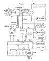
- the air conditioning system comprises an air duct 1 which is provided therein with a switch door 2, a blower 3 and an evaporator 4.
- the switch door 2 is manually switched over to selectively open first and second inlets 1a, 1b of the air duct 1, as shown by solid and dotted lines in Figure 1.
- first inlet 1 a When the first inlet 1 a is opened, the air to be conditioned is taken from outside the automobile into the air duct 1.
- the second inlet 1b is opened, the air to be conditioned is taken from inside a passenger compartment 8 of the automobile into the air duct 1.
- the blower 3 receives electric power supply from a battery by actuation of a blower switch such that it is driven to impel the air from one of inlets 1 a, 1 b toward the evaporator 4.
- a blower switch such that it is driven to impel the air from one of inlets 1 a, 1 b toward the evaporator 4.
- refrigerant liquid in the evaporator 4 is evaporated by heat of the air to extract heat from the air.
- the heat- extracted or cooled air is dehumidified and applied by evaporator 4 to an air-blend door 7, whereas the evaporated liquid is circulated into a refrigerant compressor 5 as refrigerant gases.
- the compressor 5 includes an electromagnetic clutch 5a which is coupled to an engine for the automobile.
- the clutch 5a is selectively energized by operation of the electric control apparatus, as described below, to connect the compressor 5 with the engine.
- the compressor. 5 When the compressor. 5 is driven by the engine, the refrigerant gases are compressed by the compressor 5 into high-pressurized ones and condensed by a condenser into high-pressurized refrigerant liquid.
- the refrigerant liquid from the condenser is changed by an expansion valve into low-pressurized refrigerant liquid with low temperature to be circulated into the evaporator 4.
- the air-blend door 7 is provided within the air duct 1 and coupled by an operating rod 19a to an actuator 19.
- the actuator 19 is an electrically operated vacuum actuator having a well-known construction and serves to displace the rod 19a by operation of the electric control apparatus, as described below, to control an opening degree 8 of the air-blend door 7 (See Figure 1) to an optimum value.
- the cooled air from the evaporator 4 is partly applied to and warmed by a heater 6 in accordance with the opening degree 0 of the door 7 and flows into the passenger compartment 8, and the remainder of the cooled air flows directly into the compartment 8. This means that the proportion of the warm and cold air is controlled by the air-blend door 7 to maintain temperature of air in the compartment 8 at a desired value.
- the maximum surplus cooling ability of the air conditioning system is defined as the difference between the maximum and minimum cooling abilities and that surplus cooling ability of the air conditioning system decreases in accordance with decrease of the opening degree 8 of the door 7.
- the heater 6 receives heat energy of water in the engine coolant system to warm the cold air from evaporator 4.
- the electric control apparatus comprises an analog-to-digital converter 16 connected to sensors 9, 10, -11 and a temperature selector 12.
- the in-car sensor 9 is provided within the passenger compartment 8 such that it detects instant temperature T in of air in the compartment 8 to produce an electric signal indicative of the instant in-car temperature T in .
- the outside ambient sensor 11 is located near the condenser to detect instant ambient temperature Tm outside the automobile so as to produce an electric signal indicative of the instant ambient temperature T am .
- the door position sensor 10 is a potentiometer coupled to the operating rod 19a of the actuator 19. The potentiometer detects a displacement of the rod 19a to produce an electric signal indicative of the instant opening degree 8 of the air-blend door 7.
- the temperature selector 12 is provided within the passenger compartment 8 and serves to manually select in-car temperature at a desired value to produce an electric signal indicative of the selected in-car temperature. All the electric signals from the sensors 9, 10, 11 and temperature selector 12 are respectively applied to and converted by the converter 16 into electric binary signals.
- the electric control apparatus also comprises a digital computer 17 connected to a starter switch 13, a speed sensor 14 and the converter 16. Each of the binary signals from the converter 16 is applied to the computer 17 when required by the computer 17.
- the starter switch 13 is provided within an ignition switch in the form of a manually operable switch for the engine. When the ignition switch is actuated, the starter switch 13 is temporarily closed to produce an electric signal indicative of driving a starter motor for the engine.
- the speed sensor 14 is provided on the engine to produce an electric pulse signal with a frequency corresponding with rotational speed of the engine. The electric signals from the starter switch 13 and speed sensor 14 are respectively applied to the digital computer 17.
- the digital computer 17 is a single chip LSI microcomputer and serves to receive a constant . voltage from a voltage stabilizer so as to be ready for its operation.
- the voltage stabilizer receives the electric power supply from the battery by actuation of the ignition switch' to produce the constant voltage therefrom.
- the digital computer 17 comprises a central processing unit or CPU which is connected to an input-output device or 1/0 through a data bus 17a.
- CPU is also connected through data bus 17a to a clock circuit 17b, a read only memory or ROM, and a random access memory or RAM.
- 1/0 receives the binary signals from converter 16 and the electric signal from starter switch 13 to temporarily memorize them in RAM. These memorized signals are selectively read out and applied to CPU through data bus 17a.
- CPU serves to execute a predetermined computer program in accordance with clock signals from the clock circuit 176.
- the clock circuit 17b is cooperable with a crystal oscillator 18 to produce the clock signals at a predetermined frequency.
- the predetermined program is previously stored in ROM to be executed in the computer 17 as in the following.
- the value T B indicates an expected in-car temperature corresponding with an optimum opening degree of door 7 under activation of the compressor 5.
- a microcomputer of 8048 type manufactured by INTEL CORP. has been used as the computer 17 due to its commercial availability. Detail description regarding the microcomputer is eliminated because the particular construction and programming process are well known in the prior art.
- a drive circuit 20 receives the first control signal from computer 17 such that it produces an electric deenergization signal to deenergize the clutch 5a.
- the drive circuit 20 also receives the second control signal from computer 17 such that it produces an electric energization signal to energize the clutch 5a.
- the electric signals from the starter switch 13 and speed sensor 14 are respectively applied to I/O, the former being memorized in RAM by I/O. Then, CPU calculates a value indicative of cranking speed of the engine in accordance with the pulse signal with the engine cranking speed frequency from 1/0, the calculated value being temporarily memorized in RAM.
- instant in-car temperature T in in the passenger compartment 8 is detected by and produced from the in-car sensor 9 as an electric signal indicative of the instant in-car temperature T in
- instant ambient temperature T am outside the automobile is detected by and produced from the ambient sensor 11 as an electric signal indicative of the instant ambient temperature T am
- An instant opening degree ⁇ of the air-blend door 7 is detected by and produced from the door position sensor 10 as an electric signal indicative of the instant door opening degree ⁇ .
- a desired in-car temperature is manually selected by the temperature selector 12
- an electric signal indicative of the selected in-car temperature is produced from the selector 12.
- the electric signals from the sensors 9, 10, 11 1 and selector 12 are respectively converted by the converter 16 and applied to the computer 17 as electric binary signals.
- the binary signals from the converter 16 are respectively applied to and temporarily memorized in RAM.
- CPU reads out the electric signal indicative of driving the starter motor from RAM and thereafter discriminates as "yes", the program proceeding to a point 104. Then, a first control signal is produced from CPU on a basis of the discriminated result at point 103 and is applied to the drive circuit 20. Subsequently, an electric deenergization signal is produced from the drive circuit 20 in response to the first control signal from computer 17 and is applied to the electromagnetic clutch 5a. When the clutch 5a is deenergized due to the electric deenergization signal, it is disengaged to disconnect the compressor 5 from the engine.
- the binary signal indicative of the ambient temperature T, m is read out from RAM, and the first temperature coefficient K, is read out from ROM.
- CPU calculates a value M. from the equation (1) in accordance with the temperature T am and coefficient K 1 and proceeds the program to the following point 119.
- the binary signals respectively indicative of the in-car temperature T in , ambient temperature T am and door opening degree 8 are respectively read out from RAM, and the second to fourth temperature coefficients K 2 , K 3 , K 4 are respectively read out from ROM.
- CPU calculates a value T " from the equation (2) in accordance with the - calculated value M F , in-car and ambient temperatures T in , T am , door opening degree 0 and coefficients K 2 , K 3 , K 4 .
- the computer program proceeds to points 120, 121, and the calculated value T A from CPU is applied to the actuator 19 as a third control signal.
- the actuator 19 is actuated such that the operating rod 19a is displaced to control the opening degree of the air-blend door 7 toward a zero value.
- the predetermined compensation speed value is read out from ROM, and the predetermined low speed value is compensated by CPU such that it takes a higher value by the predetermined compensation speed value.
- This provides hysteresis in the electric control apparatus for preventing oscillation between the point 106 and a point 108 in the computer program.
- the compensated low speed value is temporarily memorized in RAM, and the program proceeds to point 116.
- CPU calculates a value M F from the equation (1) in accordance with the first temperature coefficient K 1 from ROM and a binary signal indicative of ambient temperature T am from RAM.
- CPU also calculates a value T A from the equation (2) in accordance with the calculated value M F , in-car and ambient temperature T in , T am , door opening degree 0, and second to fourth temperature coefficents K 2 , K 3 , K 4 .
- T A is applied to the actuator 19 from CPU as a third control signal, the actuator 19 is actuated to displace the operating rod 19a such that the opening degree of air-blend door 7 approaches to the zero value.
- the compensated low speed value obtained at point 107 is cancelled, and the predetermined low speed value is set to provide hysteresis in the electric control apparatus for preventing oscillation between the points 106 and 108 in the computer program.
- the binary signals respectively indicative of the selected in-car temperature and the instant in-car temperature are read out from RAM, and CPU discriminates as "no" because the instant in-car temperature is higher than the selected in-car temperature, the computer program proceeding to a point 113 through a point 112.
- the opening degree of the door 7 substantially becomes the zero value, as previously described. This means that there is no surplus cooling ability in the air conditioning system.
- CPU discriminates as "no" on a basis of the above description, it proceeds the program to a point 118 through a point 117. Then, CPU produces a second control signal which is applied to the drive circuit 20. Subsequently, the drive circuit 20 produces an electric energization signal in response to the second control signal from computer 17 and, in turn, applies the same to the clutch 5a.
- the clutch 5a is engaged to connect the compressor 5 to the engine, and the compressor 5 is driven to compress refrigerant gases which are circulated into the evaporator 4 as refrigerant liquid, as previously described.
- CPU discriminates as "yes" at point 113 and proceeds the computer program to a point 114. Then, a first control signal is produced from and applied by CPU to the drive circuit 20 to generate an electric deenergization signal from the drive circuit 20. Thus, the clutch 5a is disengaged to disconnect the compressor 5 from the engine.
- the predetermined door opening degree is compensated such that it takes a smaller value by the predetermined compensation door opening degree.
- This provides hysteresis in the electric control apparatus for preventing . oscillation between the points 114 and 117 in the computer program.
- the compensated door opening degree is memorized in RAM, and the program proceeds to points 116, 119. Then, values M F , T A are respectively calculated by CPU, as previously described, the computer program proceeding to points 120, 121.
- the actuator 19 starts to control displacement of the rod 19a such that the door opening degree is decreased to maintain instant in-car temperature at the selected in-car temperature.
- the above-noted execution in computer 17 is repetitively conducted to gradually decrease the door opening degree toward the compensated door opening degree to maintain the in-car temperature at the selected in-car temperature.
- the decreased door opening degree is detected by the door position sensor 10 and applied to the converter 16 as an electric signal.
- the electric signal from sensor 10 is converted by the converter 16 and applied as a binary signal to computer 17 at point 102 together with other binary signals from converter 16. Then, the binary signals are temporarily memorized in RAM.
- CPU discriminates as "no" because the decreased door opening degree is below the compensated door opening degree, the computer program proceeding to point 117. Then, the compensated door opening degree is cancelled, and the predetermined opening degree is again memorized in RAM.
- a second control signal is produced from CPU on a basis of the discriminated result at point 113 and is applied to the drive circuit 20 at point 118.
- the drive circuit 20 produces an electric energization signal in response to the second control signal from computer 17, the clutch 5a is engaged in response to the energization signal to connect the compressor to the engine so as to activate the compressor 5.
- refrigerant gases are compressed by the compressor 5 and applied to the evaporator 4 as refrigerant liquid, as previously described.
- the air from the blower 3 is cooled through the evaporator 4 under activation of compressor 5.
- a value T is calculated by CPU, as previously described.
- the calculated value T is applied to the actuator 19 as a third control signal at points 120, 121.
- the actuator 19 starts to control displacement of the rod 19a such that the door opening degree is changed toward the predetermined opening degree memorized in RAM at point 117.
- the in-car temperature is detected by the in-car sensor 9 and applied to the converter 16 as an electric signal. Then, the electric signal from sensor 9 is converted by the converter 16 together with other electric signals from sensors 9, 11 and selector 12 into binary signals.
- the binary signals from converter 16 are applied to and memorized in RAM at point 102.
- the computer program proceeds to point 109, the binary signals respectively indicative of the lowered in-car temperature and the selected temperature are read out from RAM, and CPU discriminates as "yes" because the in-car temperature is lower than the selected temperature.
- a first control signal is produced from CPU and applied to the drive circuit 20. Then, in electric deenergization signal is produced from the drive circuit 20 in response to the first control signal from computer 17 and is applied to the clutch 5a.
- the clutch 5a is disengaged to disconnect the compressor 5 from the engine.
- the selected temperature and the predetermined compensation temperature are respectively read out from RAM and ROM, and the selected temperature is compensated such that it takes a higher value by the predetermined compensation temperature.
- the compensated selected temperature is memorized in RAM, and the program proceeds to points 116, 119.
- values M F , T are respectively calculated by CPU, as previously described. Thereafter, at points 120, 121 the calculated value T A is produced from and applied by CPU to the actuator 19 as a third control signal.
- the actuator 19 starts to control displacement of the rod 19a so that the door opening degree 8 is decreased to maintain the in-car temperature below the compensated selected temperature. From the above description, it will be noted that under deactivation of the compressor 5, the above-noted execution in computer 17 is repetitively conducted to gradually decrease the door opening degree until the in-car temperature reaches the compensated selected temperature obtained at point 111.
- a value T e is calculated by CPU, as previously described, and applied to the actuator 19 as a third control signal at points 120, 121.
- the actuator 19 starts to control displacement of the rod 19a so that the door opening degree is varied to lower the in-car temperature toward the selected temperature.
- the door position sensor 10 is utilized to detect the surplus cooling ability of the air conditioning system, it may be replaced by the in-car and ambient sensors 9, 11.
- the predetermined program stored in the computer 17 is modified such that the computer 17 detects the surplus cooling ability of the air conditioning system from a desired relationship between surplus cooling ability of the air conditioning system, temperature of air within the passenger compartment and temperature of air outside the automobile.
- the desired relationship described above is experimentally obtained in relation to the air conditioning system.
- the predetermined program stored in the computer 17 may be modified such that the computer 17 detects the fact that ambient temperature outside the automobile is lower than in-car temperature within the compartment 8 and produces a first control signal indicative of deactivation of the compressor 5. Furthermore, the predetermined program stored in the computer 17 may be modified such that the computer 17 detects the surplus cooling ability of the air conditioning system in dependence upon difference between in-car temperature within the compartment 8 and ambient temperature outside the automobile, and travel speed of the automobile. With this modification, unnecessary losses of the engine output power will be avoided more effectively.
Landscapes
- Engineering & Computer Science (AREA)
- Physics & Mathematics (AREA)
- General Physics & Mathematics (AREA)
- Automation & Control Theory (AREA)
- Thermal Sciences (AREA)
- Mechanical Engineering (AREA)
- Remote Sensing (AREA)
- Air-Conditioning For Vehicles (AREA)
- Air Conditioning Control Device (AREA)
Claims (6)
Applications Claiming Priority (2)
| Application Number | Priority Date | Filing Date | Title |
|---|---|---|---|
| JP87908/78 | 1978-07-18 | ||
| JP53087908A JPS5911446B2 (ja) | 1978-07-18 | 1978-07-18 | 車両用空調制御装置 |
Publications (3)
| Publication Number | Publication Date |
|---|---|
| EP0007775A1 EP0007775A1 (de) | 1980-02-06 |
| EP0007775B1 true EP0007775B1 (de) | 1982-06-02 |
| EP0007775B2 EP0007775B2 (de) | 1986-03-05 |
Family
ID=13928004
Family Applications (1)
| Application Number | Title | Priority Date | Filing Date |
|---|---|---|---|
| EP79301430A Expired EP0007775B2 (de) | 1978-07-18 | 1979-07-18 | Verfahren und Vorrichtung zur elektrischen Regelung von Kraftfahrzeugklimaanlagen |
Country Status (4)
| Country | Link |
|---|---|
| US (1) | US4340113A (de) |
| EP (1) | EP0007775B2 (de) |
| JP (1) | JPS5911446B2 (de) |
| DE (1) | DE2963003D1 (de) |
Families Citing this family (29)
| Publication number | Priority date | Publication date | Assignee | Title |
|---|---|---|---|---|
| USRE31582E (en) * | 1979-03-23 | 1984-05-08 | Nissan Motor Company, Limited | Automatic control system for method and apparatus for checking devices of an automotive vehicle in use with a microcomputer |
| JPS565213A (en) * | 1979-06-22 | 1981-01-20 | Nippon Denso Co Ltd | Controlling method and system for car air conditioner |
| JPS5643014A (en) * | 1979-09-12 | 1981-04-21 | Nippon Denso Co Ltd | Controlling method and apparatus for taking-in inside and outside air |
| JPS5650809A (en) * | 1979-10-01 | 1981-05-08 | Nippon Denso Co Ltd | Power-saving method and apparatus for controlling air-conditioning |
| JPS5686814A (en) * | 1979-12-12 | 1981-07-15 | Nippon Denso Co Ltd | Air conditioning controller for car |
| JPS56103611A (en) * | 1980-01-16 | 1981-08-18 | Nippon Denso Co Ltd | Controlling method for power-saving air-conditioner |
| JPS5948168B2 (ja) * | 1980-04-10 | 1984-11-24 | 株式会社ボッシュオートモーティブ システム | 車輛用空気調和装置の制御方法 |
| JPS5777214A (en) * | 1980-11-04 | 1982-05-14 | Nissan Motor Co Ltd | Air conditioner for vehicle |
| JPS5777216A (en) * | 1980-11-04 | 1982-05-14 | Nissan Motor Co Ltd | Air conditioner for vehicle |
| JPS5777215A (en) * | 1980-11-04 | 1982-05-14 | Nissan Motor Co Ltd | Air conditioner for vehicle |
| JPS5777217A (en) * | 1980-11-04 | 1982-05-14 | Nissan Motor Co Ltd | Air conditioner for vehicle |
| JPS5943327B2 (ja) * | 1980-12-02 | 1984-10-22 | 株式会社デンソー | 車両用空調制御装置 |
| JPS5799415A (en) * | 1980-12-12 | 1982-06-21 | Mitsubishi Heavy Ind Ltd | Car air conditioner controller |
| JPS57118914A (en) * | 1981-01-16 | 1982-07-24 | Nissan Motor Co Ltd | Air conditioning units for vehicles |
| US4441405A (en) * | 1981-03-12 | 1984-04-10 | Nissan Motor Company, Limited | Solar radiation heat influx sensor for an automotive vehicle |
| SE436112B (sv) * | 1981-04-01 | 1984-11-12 | Saab Scania Ab | Klimatsystem for fordon |
| JPS6027905B2 (ja) * | 1981-04-03 | 1985-07-02 | トヨタ自動車株式会社 | 空調制御方法 |
| JPS58110317A (ja) * | 1981-12-23 | 1983-06-30 | Mitsubishi Heavy Ind Ltd | 車輌用空調装置 |
| DE3302322C2 (de) * | 1983-01-25 | 1985-04-18 | Daimler-Benz Ag, 7000 Stuttgart | Einrichtung zum Regeln der Innenraumtemperatur eines Kraftfahrzeuges |
| JPS6012326A (ja) * | 1983-07-01 | 1985-01-22 | Nissan Motor Co Ltd | 車両用空気調和装置 |
| JPS60193711A (ja) * | 1984-03-15 | 1985-10-02 | Diesel Kiki Co Ltd | 自動車用空調装置の制御装置 |
| US4766950A (en) * | 1984-05-31 | 1988-08-30 | Mitsubishi Jukogyo Kabushiki Kaisha | Controller for an air conditioner of vehicles |
| US5211331A (en) * | 1990-04-13 | 1993-05-18 | Roberts-Gordon, Inc. | Control in combination with thermostatically responsive assembly |
| JP3190753B2 (ja) * | 1992-12-04 | 2001-07-23 | 正和 大澤 | 小型高速船 |
| US5538472A (en) * | 1994-10-26 | 1996-07-23 | Case Corporation | Agricultural vehicle cab temperature control system |
| US5993312A (en) * | 1997-12-22 | 1999-11-30 | Case Corporation | Agricultural vehicle cab automatic temperature control system |
| JP3965753B2 (ja) * | 1997-12-25 | 2007-08-29 | 株式会社デンソー | 車両用空調装置 |
| JP2001121951A (ja) * | 1999-10-29 | 2001-05-08 | Sanden Corp | 車両用空調装置 |
| DE102013220249A1 (de) * | 2013-10-08 | 2015-04-09 | Visteon Global Technologies, Inc. | Klimaanlage eines Kraftfahrzeuges |
Family Cites Families (13)
| Publication number | Priority date | Publication date | Assignee | Title |
|---|---|---|---|---|
| US2829869A (en) * | 1955-05-06 | 1958-04-08 | American Motors Corp | Refrigerating apparatus |
| US3004752A (en) * | 1959-01-12 | 1961-10-17 | Gen Motors Corp | Integrated automotive heating and air conditioning systems |
| US3112791A (en) * | 1959-04-16 | 1963-12-03 | United Aircraft Corp | Air conditioning control |
| US3315730A (en) * | 1964-12-21 | 1967-04-25 | Bendix Corp | Control system for automobile air conditioners |
| US3667245A (en) * | 1970-06-08 | 1972-06-06 | James Peter Till | Fan and clutch control circuit for an air conditioner |
| US3686891A (en) * | 1970-09-21 | 1972-08-29 | Borg Warner | Electronic safety control system for vehicle compressors |
| US3771593A (en) * | 1970-10-12 | 1973-11-13 | Air A Plane Corp | Air supply device for air heating and cooling system |
| US3983930A (en) * | 1973-09-24 | 1976-10-05 | Eaton Corporation | Temperature control system and multifunctional servomotor therefor |
| DE2430566A1 (de) * | 1974-06-26 | 1976-01-15 | Basf Ag | Gemische von verbindungen der naphthalimidreihe |
| JPS5191542A (de) * | 1975-02-07 | 1976-08-11 | ||
| JPS5235204A (en) * | 1975-09-16 | 1977-03-17 | Kao Corp | Clear high viscous liuid shampoo composition |
| JPS5238287A (en) * | 1975-09-22 | 1977-03-24 | Hitachi Ltd | Sample treating device |
| US4147205A (en) * | 1977-09-12 | 1979-04-03 | The Bendix Corporation | Vacuum actuated automatic temperature control system with actuator pressure signal feedback |
-
1978
- 1978-07-18 JP JP53087908A patent/JPS5911446B2/ja not_active Expired
-
1979
- 1979-07-17 US US06/058,383 patent/US4340113A/en not_active Expired - Lifetime
- 1979-07-18 EP EP79301430A patent/EP0007775B2/de not_active Expired
- 1979-07-18 DE DE7979301430T patent/DE2963003D1/de not_active Expired
Also Published As
| Publication number | Publication date |
|---|---|
| JPS5515349A (en) | 1980-02-02 |
| JPS5911446B2 (ja) | 1984-03-15 |
| EP0007775A1 (de) | 1980-02-06 |
| EP0007775B2 (de) | 1986-03-05 |
| US4340113A (en) | 1982-07-20 |
| DE2963003D1 (en) | 1982-07-22 |
Similar Documents
| Publication | Publication Date | Title |
|---|---|---|
| EP0007775B2 (de) | Verfahren und Vorrichtung zur elektrischen Regelung von Kraftfahrzeugklimaanlagen | |
| EP0026612B1 (de) | Verfahren und System zur elektrischen Regelung einer Kraftfahrzeugklimaanlage | |
| US4408713A (en) | Control for automobile air conditioning system | |
| US4316251A (en) | Electric control method for automobile air conditioner | |
| EP0019416B1 (de) | Vorrichtung zur Steuerung einer Klimaanlage | |
| US5775415A (en) | Air conditioning system | |
| US4328855A (en) | Method and apparatus for controlling automobile air conditioners | |
| US8047274B2 (en) | Air conditioner for vehicle | |
| US4365663A (en) | Method and system for controlling a vehicle-mounted air conditioner | |
| US4325426A (en) | Air conditioner system | |
| US5669226A (en) | Air conditioning apparatus for a vehicle | |
| US4456055A (en) | Automotive air conditioner having coating power control device | |
| US20070107455A1 (en) | Method for the automatic starting and stopping of an internal combustion engine | |
| US4877081A (en) | Air-conditioning apparatus for automobiles | |
| JPS5939333B2 (ja) | 車両用空気調和装置の温度制御装置 | |
| JPS6213209B2 (de) | ||
| JPS625804B2 (de) | ||
| JPS58105820A (ja) | 車両用空気調和装置の湿度制御方法 | |
| JPH0729539B2 (ja) | 自動車用空調装置制御方法 | |
| EP0102397A1 (de) | Luftkonditionierungsverfahren und vorrichtung für fahrzeuge | |
| JPH0569006B2 (de) | ||
| JP3146675B2 (ja) | 空気調和装置 | |
| JPH03291463A (ja) | 冷房サイクルの過熱度制御装置 | |
| JPS6228011B2 (de) | ||
| JPS6144901Y2 (de) |
Legal Events
| Date | Code | Title | Description |
|---|---|---|---|
| PUAI | Public reference made under article 153(3) epc to a published international application that has entered the european phase |
Free format text: ORIGINAL CODE: 0009012 |
|
| AK | Designated contracting states |
Designated state(s): DE FR GB |
|
| 16A | New documents despatched to applicant after publication of the search report | ||
| 17P | Request for examination filed | ||
| GRAA | (expected) grant |
Free format text: ORIGINAL CODE: 0009210 |
|
| AK | Designated contracting states |
Designated state(s): DE FR GB |
|
| REF | Corresponds to: |
Ref document number: 2963003 Country of ref document: DE Date of ref document: 19820722 |
|
| PLBI | Opposition filed |
Free format text: ORIGINAL CODE: 0009260 |
|
| PLAB | Opposition data, opponent's data or that of the opponent's representative modified |
Free format text: ORIGINAL CODE: 0009299OPPO |
|
| 26 | Opposition filed |
Opponent name: SUEDDEUTSCHE KUEHLERFABRIK JULIUS FR. BEHR GMBH & Effective date: 19830218 |
|
| R26 | Opposition filed (corrected) |
Opponent name: SUEDDEUTSCHE KUEHLERFABRIK JULIUS FR. BEHR GMBH & Effective date: 19830218 |
|
| REG | Reference to a national code |
Ref country code: GB Ref legal event code: 746 |
|
| PUAH | Patent maintained in amended form |
Free format text: ORIGINAL CODE: 0009272 |
|
| STAA | Information on the status of an ep patent application or granted ep patent |
Free format text: STATUS: PATENT MAINTAINED AS AMENDED |
|
| 27A | Patent maintained in amended form |
Effective date: 19860305 |
|
| AK | Designated contracting states |
Kind code of ref document: B2 Designated state(s): DE FR GB |
|
| ET | Fr: translation filed | ||
| PGFP | Annual fee paid to national office [announced via postgrant information from national office to epo] |
Ref country code: GB Payment date: 19970709 Year of fee payment: 19 Ref country code: FR Payment date: 19970709 Year of fee payment: 19 |
|
| PGFP | Annual fee paid to national office [announced via postgrant information from national office to epo] |
Ref country code: DE Payment date: 19970725 Year of fee payment: 19 |
|
| PG25 | Lapsed in a contracting state [announced via postgrant information from national office to epo] |
Ref country code: GB Free format text: LAPSE BECAUSE OF NON-PAYMENT OF DUE FEES Effective date: 19980718 |
|
| GBPC | Gb: european patent ceased through non-payment of renewal fee |
Effective date: 19980718 |
|
| PG25 | Lapsed in a contracting state [announced via postgrant information from national office to epo] |
Ref country code: FR Free format text: LAPSE BECAUSE OF NON-PAYMENT OF DUE FEES Effective date: 19990331 |
|
| PG25 | Lapsed in a contracting state [announced via postgrant information from national office to epo] |
Ref country code: DE Free format text: LAPSE BECAUSE OF NON-PAYMENT OF DUE FEES Effective date: 19990501 |
|
| REG | Reference to a national code |
Ref country code: FR Ref legal event code: ST |