EP0008279A2 - Cartouche amovible pour ruban encreur de machine à écrire et machine à écrire y relative - Google Patents
Cartouche amovible pour ruban encreur de machine à écrire et machine à écrire y relative Download PDFInfo
- Publication number
- EP0008279A2 EP0008279A2 EP79830023A EP79830023A EP0008279A2 EP 0008279 A2 EP0008279 A2 EP 0008279A2 EP 79830023 A EP79830023 A EP 79830023A EP 79830023 A EP79830023 A EP 79830023A EP 0008279 A2 EP0008279 A2 EP 0008279A2
- Authority
- EP
- European Patent Office
- Prior art keywords
- ribbon
- cartridge
- typewriter
- arm
- spool
- Prior art date
- Legal status (The legal status is an assumption and is not a legal conclusion. Google has not performed a legal analysis and makes no representation as to the accuracy of the status listed.)
- Withdrawn
Links
- 238000004804 winding Methods 0.000 claims description 22
- 241000582342 Carria Species 0.000 description 1
- 238000006073 displacement reaction Methods 0.000 description 1
- 230000037431 insertion Effects 0.000 description 1
- 238000003780 insertion Methods 0.000 description 1
- 230000010355 oscillation Effects 0.000 description 1
- 230000002093 peripheral effect Effects 0.000 description 1
- 230000000284 resting effect Effects 0.000 description 1
- 230000000717 retained effect Effects 0.000 description 1
- 210000000332 tooth crown Anatomy 0.000 description 1
Images


Classifications
-
- B—PERFORMING OPERATIONS; TRANSPORTING
- B41—PRINTING; LINING MACHINES; TYPEWRITERS; STAMPS
- B41J—TYPEWRITERS; SELECTIVE PRINTING MECHANISMS, i.e. MECHANISMS PRINTING OTHERWISE THAN FROM A FORME; CORRECTION OF TYPOGRAPHICAL ERRORS
- B41J33/00—Apparatus or arrangements for feeding ink ribbons or like character-size impression-transfer material
- B41J33/14—Ribbon-feed devices or mechanisms
- B41J33/16—Ribbon-feed devices or mechanisms with drive applied to spool or spool spindle
- B41J33/18—Ribbon-feed devices or mechanisms with drive applied to spool or spool spindle by ratchet mechanism
-
- B—PERFORMING OPERATIONS; TRANSPORTING
- B41—PRINTING; LINING MACHINES; TYPEWRITERS; STAMPS
- B41J—TYPEWRITERS; SELECTIVE PRINTING MECHANISMS, i.e. MECHANISMS PRINTING OTHERWISE THAN FROM A FORME; CORRECTION OF TYPOGRAPHICAL ERRORS
- B41J32/00—Ink-ribbon cartridges
-
- B—PERFORMING OPERATIONS; TRANSPORTING
- B41—PRINTING; LINING MACHINES; TYPEWRITERS; STAMPS
- B41J—TYPEWRITERS; SELECTIVE PRINTING MECHANISMS, i.e. MECHANISMS PRINTING OTHERWISE THAN FROM A FORME; CORRECTION OF TYPOGRAPHICAL ERRORS
- B41J33/00—Apparatus or arrangements for feeding ink ribbons or like character-size impression-transfer material
- B41J33/14—Ribbon-feed devices or mechanisms
- B41J33/40—Ribbon-feed devices or mechanisms with arrangements for reversing the feed direction
- B41J33/44—Ribbon-feed devices or mechanisms with arrangements for reversing the feed direction automatically
- B41J33/51—Ribbon-feed devices or mechanisms with arrangements for reversing the feed direction automatically and characterised by the use of particular reversing control means
- B41J33/512—Ribbon-feed devices or mechanisms with arrangements for reversing the feed direction automatically and characterised by the use of particular reversing control means using a pivoted reversing-feeler engaging the external periphery of the wound ribbon
-
- B—PERFORMING OPERATIONS; TRANSPORTING
- B41—PRINTING; LINING MACHINES; TYPEWRITERS; STAMPS
- B41J—TYPEWRITERS; SELECTIVE PRINTING MECHANISMS, i.e. MECHANISMS PRINTING OTHERWISE THAN FROM A FORME; CORRECTION OF TYPOGRAPHICAL ERRORS
- B41J35/00—Other apparatus or arrangements associated with, or incorporated in, ink-ribbon mechanisms
- B41J35/04—Ink-ribbon guides
Definitions
- the invention is related to a particular cartridge for inked ribbon and a typewriter adapted for its employ, which typewriter is foreseen to raise the roller carriage to pass from small letters to capital letters and said particular ribbon carrier cartridge is moved integrally with said roller carriage for the passage from small letters to capital one.
- said cartridge contains two spools, one spool being apt to unwind the ribbon and the other spool to wind the same ribbon, the latter beinq carried before the operated types by an arm articulated to the same cartridge, which arm is raised by oscillation at each operation with means inside the cartridge, which means provide further for the advancing movement of the same ribbon.
- ribbon carrier cartridges for typewriters and relative typewriters are known, on said typewriters the cartridges are mounted and operated, said cartridges presenting different disadvantages according to the disposition of the spools and the means provided for advancing same.
- the types of cartridges having separated and spaced spool, the ribbon of which is positioned before the operated types within the interval of the two spools, are very large, cumbersome and difficult to replace.
- said cartridges are very expensive and are apt only for relatively important machines.
- the latter must be also of the type wherein the passage from small letters to capital one is accomplished by a movement of the whole type assembly.
- the typewriter according to the invention with the relati ve particular cartridge completely solves the problem of feeding and replacing the ribbon, as the cartridges can be manufactured in an easy and economical way, while the inked ribbon can be of any type, having a height sufficient only for the capital types; for this reason it becomes possible to employ the cartridge only once and further it is possible to invert the ribbon rotation with self-regerating ribbons and to use said ribbon for a lot of times without replacing it.
- the typewriter according to the invention, provides for means raising the roller carriage for the operation of the capital letters and means raising likewise the whole cartridge together with the said carriage, so that the relative position between the ribbons and the paper carrier roller does not change during the typing. Ih addition it is foreseen, according to the invention, to pass, in correspondance with the operation zone, the ribbon on itself using particularly thin ribbons, the width of which is that required by the highest capital letter.
- the typewriter is composed by a swinging support for the roller carriage, on said support a ribbon carrier cartridge is applied, said support being operated by the capital letter key, which key provides, be means of levers and tension rods, to raise the carriage and cartridge assembly up to the position requested for typewriting the capital letters.
- Said cartridge comprises, according to the invention, a casing into which are disposed two spools which can be coaxial, superimposed and idle on a common shaft or juxtaposed, on said spools the ribbon is unwound from one spool and rewound to the other spool. Pivoted on said casing and substantially parallel to the paper carrier roller axis, a swinging arm is disposed, the latter guiding the ribbon in the forward movement up to its fork-shaped end, wherein the ribbon is inverted passing on itself, and in the backward movement.
- the winding movement to the respective spool is furnished by a swinging lever, pivoted inside the casing and having three arms.
- a first arm of said lever passes through the casing bottom and projects below, the second arm slides along a cam shaped slit of said swinging arm and the third arm, acting as a spring for being constituted by a resilient strip, engages inclined teeth obtained on the ribbon winding spool edge.
- a blade or the like pivoted in the lower portion of the same typewriter and connected through a tension rod or the like with the typewriter universal bar operated, as it is known, by any key of the same machine. Said swinging blade engages, in its turn, the first arm of said swinging lever.
- the ribbon carrier arm swings carrying the ribbon between the type and the paper carrier roller, while at the same time the winding spool causes the ribbon to advance a step presenting a new portion before the type for the operation.
- each of the two coaxial and juxtaposed spools is provided with a respective crown gear while the third arm of the swinging lever is divided in two parts with relative teeth apt to engage either crown gear of the two spools.
- one of said teeth of the said third arm is carried out of engagement with the respective crown gear, through a bistable swinging arm, carried in either stable position by means of a follower in the form of a rocker lever contacting the winding ribbon, and kept in such a position by an over-centre spring.
- the said follower contacting the winding ribbon automatically passes the over-centre snap point of the spring when it reaches a certain position of full spool, carrying the bistable arm in the other position, for this reason the operating tooth, which was engaged with a spool, is carried out of engagement with the same spool, while the other tooth is at the same time carried in engagement with the other spool.
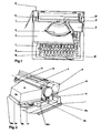
- the typewriter shown in top and side views, is generally traditional. and comprises a frame 1, a keyboard 2, a cover 3, a type assembly 4, a movable carriage 5 provided with a paper carrier roller 6 and a paper advancing lever 7.
- a cartridge 8 is located on the typewriter right side (in this case the position is given only for reference) near the carriage 5, comprising inside a ribbon 9 which projects from the cartridge housing and is guided on a ribbon carrier arm 10 combined with the cartridge on the backward side, as it will be explained afterwards.
- the roller carriage 5 presents the paper carrier roller 6 in a position apt to receive the operations of the type-bars with their lower type, generally small types; while in the raised position of the roller carriage, the roller 6 is positioned in front of the upper types, generally capital types, ciphers and the like, of the type bars 4.
- the change of the position, from lowered to raised, is provided for the roller carriage 5 by acting on the lever 11 through the key "M" (capital), the tension rod 13, the lever 14 pivoted in 15, with the end 14a shaped as a fork and the pin 18 integral with the lever 11.
- the angular displacement of the lever 14 is limited by two stops 17--17a for the correct positioning of the roller carriage.
- the same lever 11 is extended forwardly and supports rigidly a housing 18 provided with slide guides 18a-18b and a two-arm lever 19 pivoted in 20, having two ends 19a-19b of which the first end is provided with a hook 19' a for retaining the roller cartridge, and the second end is provided with a key 19'b projecting from the frame of the typewriter, while a spring 21 drawn between the housing 18 and one of the arms of the lever 19, tends to urge the hook shaped end 19'a toward the guide 18a.
- a spring expeller 22 is provided on said housing 18 from the side opposite to the outer one and parallelly to the guides 18a-18b.
- Said cartridge 8 presents a two-part casing, one part being a lower base 8d and the other part being a cover 8e (figure 2), being inserted in the lower portion with snap means of known type, for example projections and recesses, teeth and the like not represented.
- a swinging lever 29 is pivoted in 28, said lever having three arms of which the first arm ends with an appendix 29a downwardly directed and projecting from a window 30 of the base 8d; the second arm ends with a small tongue 29b, said tongue inserting in the said step-shaped slit t 27 of the arm 10 and the third arm is constituted by a resilient strip or the like bent on the point 29c, said sheet engaging with the crown gear 24a of the spool 21.
- a spring 29d constantly urqes the lever 29 according to the arrow B.
- a further resilient sheet 32 rigidly mounted on said base, has the Function to brake the movement of the spool 25 to maintain in tension the ribbon 9 during its travel.
- said appendix 29a of the swinging lever 29, projecting from the cartridge base 8d engages a blade 33 or the like pivoted in 34 on the base of the typewriter, said blade being urged to right by the spring 35 and to left by the tension rod 36 connected to the arm 37 of the universal bar 37a.
- Said universal bar 37a is operated by any key of the keyboard 2, only one key is represented in figure 3 for clearness.
- FIG 6 there is sidewise represented the typewriter 1 with the already cited members indicated in a continuous line, when they are in rested position and in short dashes line, when anyone of the keys 2 of the keyboard is pressed causing thereby the lever 33 to operate against the appendix 29a projecting from the cartridge 8 by means of the bar 37a and the tension rod 36 and to raise the arm 10 for carrying it before the type, which will be operated.
- Such a movement takes place both with the cartridge 8 Lowered and when it is raised, because the appendix 29a projecting below the cartridge has a lenght such to remain in contact with the blade 33, even with the cartridge in a raised position (position for the capital letters) as shown in figure 5.
- FIG. 7-8 there is shown, as a variation, an embodiment for cartridge apt to ribbons of the self-regenerating kind, for which ribbon is necessary to invert the winding direction at the end of each complete unwinding in order to re-employ many times the same ribbon.
- the cartridge and the outer control members remain equal to those already described, while the control members inside the cartridge, remaining nevertheless substantially the same, are differently conformed to alternatively control two spools, rather than only one.
- members similar to those described are indicated with the same references and members differently conformed with other references.
- the two coaxial spools rotatable around the axis 23 are provided everyone with a peripheral toothing on the lower edge and precisely the lower spool 24 has the toothed edge 24a and the upper spool 25 has the edge ?5a toothed.
- the arm 29c of the lever 29 is modified and thereon a tension blade 50 is applied divided in two parallel arms having at their ends the hooks 50a-50b apt to engage in the crown gears 24a-25a.
- the non return or retaining resilient strip 31 is divided in two arms with respective hooks 31a-31b engaged in the crown gears 24a-25a respectively and positioned below the hooks 50a-50b.
- a cam 5 1 is provided pivoted in 52 and carried in two stable positions by a lever 53 swinging around the pin 53a- said lever 53 being rigidly mounted on the follower arms 54-55 and controlled in said two extreme stable positions by a spring 56 disposed between a fixed point 57 and a movable point 58 of the lever 53, said two stable positions being obtained when the movabl 3 point 58 is located on a side or on the other side of the line joining the fixed point 57 and the rotational centre 53a.
- Said cam 51 presents two opposed profiles 51a-51b acting onto the two non return strips 31a-31b in order to alternatively raise either strip from the respective crown gears into which said strips are engaged, and raising at the same time also the hooks 50a-50b of the tension rod 50.
- Such a movement rotates the lever 53 that , in its turn, displaces the cam 51 in the position indicated in short dashes lines, carrying the follower 54 in contact with the ribbon in the spool 24 and the upper profile 51b of the cam 51 in contact with the upper retaining strip 31b, so as the upper movement ) hook 50b is raised from the toothing 25a and the lower hook 50a is engaged with the lower toothing 24a determining the rotation in opposite direction of the spool 24 and consequently the winding of the ribbon on the spool, from which spool the ribbon unwound in the previous cycle.
- the cartridge thickness determined substantially by the thickness of the two superimposed spools, can be reduced to that of only one spool disposing the same spools juxtaposed one another.
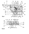
- Such an arrangement as a variation, comprising also the ribbon movement inversion means, and therefore adaptable also for self--regenerating ribbons, is shown in figures 9 and 10 corresponding to figures 7-8 of the previous embodiment.
- the members common to the already described embodiments have the same reference, while the members modified are indicated with the same reference with the addition of the apostrophe.
- the spools 24 and 25 are disposed juxtaposed, idle rotatable, on two parallel shafts 23 and 23'. Each spool is provided with toothing at the lower edge 24a-25a respectively, as in the previous case.
- the three-arm control lever 29 is still the same, except for the third arm 29'c which is pin-shaped,on said third arm is applied the end of a horizontally slidable small bar 60, the other end of which is guided in a projection 61.
- two resilient strips 50'-50" are rigidly connected having at their ends the hooks 50'a and 50"b respectively apt to engage the toothing; 24a-25a of the two spools.
- two cams 62-63 Coaxial with the same spools and idle on the shafts 23-23' two cams 62-63 respectively are disposed everyone provided with a sector gear 62a-63a respectively and a projection 62b-63b respectively apt to rest against the resilient strips 64-65 connected to the casing base and extended upwardly up to abut, in their turn, against the free end of the resilient strips 50'-50" carrying the hooks 50'a-50”b.
- Said cam 62 presents further a recess 62c into which an arm 66 connected to the follower 54-55 is located.
- Said resilient strips 64-65, apt to cooperate with said projections 62b-63b of said cams 62-63 act as retaining or non-return teeth for the spools 24-25.
- strips 64-65 besides to be resilient, are inclined in order to be engaged constantly with the respective toothings 24a-25a of said spools.
- a double resilient strip brake 32'-32" rests on both the spools accomplishing a braking action for drawing the ribbon.
- the operation of said embodiment provided with juxtaposed spools is the following: the ribbon 9 is in winding operation on the right spool 25 and the follower 55 is in contact with the same ribbon.
- the rotation movement, step by step, is furnished to the same spool 25 through the toothing 25a and the hook 50"b operated by the lever 29 with the above described means combined with the typewriter and through the sliding bar 60 into the guide 61.
- the winding diameter increases and displaces the follower 55, and consequently also the movable point 58, more and more outwardly, until the movable point 58 overcomes the line joining the fixed points 57 and 53a causing the spring 56 to snap to the other side and thus the follower 54 abuts on the ribbon of the spool 24.
- Such a movement rotates the arm 66 mounted on the followers and consequently, through the recess 62c, the cam 62 is rotated and through the toothings 62a-63a, the cam 63 is also rotated.
Landscapes
- Impression-Transfer Materials And Handling Thereof (AREA)
- Record Information Processing For Printing (AREA)
- Handling Of Continuous Sheets Of Paper (AREA)
Applications Claiming Priority (2)
| Application Number | Priority Date | Filing Date | Title |
|---|---|---|---|
| IT2643778 | 1978-08-03 | ||
| IT26437/78A IT1097931B (it) | 1978-08-03 | 1978-08-03 | Cartuccia estraibile per nastro inchiostrato per macchine da scrivere e macchina relativa |
Publications (2)
| Publication Number | Publication Date |
|---|---|
| EP0008279A2 true EP0008279A2 (fr) | 1980-02-20 |
| EP0008279A3 EP0008279A3 (fr) | 1980-05-28 |
Family
ID=11219496
Family Applications (1)
| Application Number | Title | Priority Date | Filing Date |
|---|---|---|---|
| EP79830023A Withdrawn EP0008279A3 (fr) | 1978-08-03 | 1979-07-20 | Cartouche amovible pour ruban encreur de machine à écrire et machine à écrire y relative |
Country Status (5)
| Country | Link |
|---|---|
| EP (1) | EP0008279A3 (fr) |
| DK (1) | DK326779A (fr) |
| FI (1) | FI792235A7 (fr) |
| IT (1) | IT1097931B (fr) |
| NO (1) | NO792514L (fr) |
Cited By (3)
| Publication number | Priority date | Publication date | Assignee | Title |
|---|---|---|---|---|
| EP0016657A3 (en) * | 1979-03-22 | 1981-11-04 | Ing. C. Olivetti & C., S.P.A. | Ink ribbon cartridge and actuating mechanism, and typewriter therefor |
| US4616945A (en) * | 1985-01-31 | 1986-10-14 | International Business Machines Corporation | Correction feed mechanism in a correction tape cartridge |
| EP0234254A1 (fr) * | 1986-01-21 | 1987-09-02 | Nec Corporation | Cartouche de ruban encreur équipée d'un mécanisme pour détecter la fin du ruban |
Family Cites Families (6)
| Publication number | Priority date | Publication date | Assignee | Title |
|---|---|---|---|---|
| BE703962A (fr) * | 1966-09-20 | 1968-02-01 | ||
| DE1813193A1 (de) * | 1968-12-06 | 1970-08-20 | Ecofon Probst Kg Verkaufsges | Farbband- und Kohlebandeinrichtung |
| JPS5111971B1 (fr) * | 1971-06-09 | 1976-04-15 | ||
| US3777871A (en) * | 1972-05-03 | 1973-12-11 | Scm Corp | Ribbon guide for typewriter ribbon cartridge |
| US3804227A (en) * | 1972-05-03 | 1974-04-16 | Scm Corp | Typewriter ribbon cartridge |
| US3897867A (en) * | 1973-11-12 | 1975-08-05 | Scm Corp | Ribbon feed mechanism for ink ribbon cartridges |
-
1978
- 1978-08-03 IT IT26437/78A patent/IT1097931B/it active
-
1979
- 1979-07-17 FI FI792235A patent/FI792235A7/fi not_active Application Discontinuation
- 1979-07-20 EP EP79830023A patent/EP0008279A3/fr not_active Withdrawn
- 1979-07-31 NO NO792514A patent/NO792514L/no unknown
- 1979-08-02 DK DK326779A patent/DK326779A/da unknown
Cited By (3)
| Publication number | Priority date | Publication date | Assignee | Title |
|---|---|---|---|---|
| EP0016657A3 (en) * | 1979-03-22 | 1981-11-04 | Ing. C. Olivetti & C., S.P.A. | Ink ribbon cartridge and actuating mechanism, and typewriter therefor |
| US4616945A (en) * | 1985-01-31 | 1986-10-14 | International Business Machines Corporation | Correction feed mechanism in a correction tape cartridge |
| EP0234254A1 (fr) * | 1986-01-21 | 1987-09-02 | Nec Corporation | Cartouche de ruban encreur équipée d'un mécanisme pour détecter la fin du ruban |
Also Published As
| Publication number | Publication date |
|---|---|
| IT7826437A0 (it) | 1978-08-03 |
| FI792235A7 (fi) | 1981-01-01 |
| EP0008279A3 (fr) | 1980-05-28 |
| DK326779A (da) | 1980-02-04 |
| NO792514L (no) | 1980-02-05 |
| IT1097931B (it) | 1985-08-31 |
Similar Documents
| Publication | Publication Date | Title |
|---|---|---|
| EP0038215B1 (fr) | Mécanisme d'entraînement bifonctionnel pour machines à écrire | |
| US3346090A (en) | Ribbon feed mechanism | |
| US3349887A (en) | Ribbon mechanism | |
| GB1585250A (en) | Typewriter ribbon cartridge | |
| US3915281A (en) | Platen and paper roll support and drive mechanism | |
| US4729676A (en) | Impact printing apparatus and ribbon cartridges | |
| JPH0436076B2 (fr) | ||
| EP0311982A2 (fr) | Imprimante thermique | |
| US4157224A (en) | Ribbon advancing mechanism | |
| US3532204A (en) | Spacing and ribbon feed mechanism for typewriters | |
| US4623273A (en) | Cartridge for a ribbon for typewriters | |
| CA1084436A (fr) | Machine a dactylographier | |
| US4265551A (en) | Drive for transporting and reversing an ink ribbon, and for withdrawing the printing head in printing devices | |
| US4601596A (en) | Typing and erasing device for printing machines | |
| US2811235A (en) | Machine for typing a tape record and a proof sheet simultaneously | |
| EP0021737B1 (fr) | Procédé et dispositif pour maintenir la tension d'un ruban et son application à une machine à écrire | |
| US4842427A (en) | Plotting mechanism mounted on a ribbon cassette for typewriters or office machines | |
| US4511270A (en) | Apparatus for lifting print and correction ribbons in typewriters or like machines | |
| US4373823A (en) | Ribbon guide for an inked ribbon cartridge | |
| US2366022A (en) | Typewriting machine | |
| US3991874A (en) | Automatic function mechanism for typewriters | |
| JPS5933319B2 (ja) | インクリボン駆動装置 | |
| NO792514L (no) | Kassett for skrivemaskin-baand, samt skrivemaskin tilpasset kassetten | |
| US4401395A (en) | Typewriter | |
| JPS6031991A (ja) | サ−マル転写プリンタの記録消去装置 |
Legal Events
| Date | Code | Title | Description |
|---|---|---|---|
| PUAI | Public reference made under article 153(3) epc to a published international application that has entered the european phase |
Free format text: ORIGINAL CODE: 0009012 |
|
| AK | Designated contracting states |
Designated state(s): BE CH DE FR GB NL SE |
|
| PUAL | Search report despatched |
Free format text: ORIGINAL CODE: 0009013 |
|
| AK | Designated contracting states |
Designated state(s): BE CH DE FR GB NL SE |
|
| 17P | Request for examination filed | ||
| STAA | Information on the status of an ep patent application or granted ep patent |
Free format text: STATUS: THE APPLICATION HAS BEEN WITHDRAWN |
|
| 18W | Application withdrawn |
Withdrawal date: 19810423 |