EP0008461A1 - Regeleinrichtung für Heizungs- oder Kälteanlagen - Google Patents
Regeleinrichtung für Heizungs- oder Kälteanlagen Download PDFInfo
- Publication number
- EP0008461A1 EP0008461A1 EP19790103093 EP79103093A EP0008461A1 EP 0008461 A1 EP0008461 A1 EP 0008461A1 EP 19790103093 EP19790103093 EP 19790103093 EP 79103093 A EP79103093 A EP 79103093A EP 0008461 A1 EP0008461 A1 EP 0008461A1
- Authority
- EP
- European Patent Office
- Prior art keywords
- control device
- heating
- switch
- time
- heat
- Prior art date
- Legal status (The legal status is an assumption and is not a legal conclusion. Google has not performed a legal analysis and makes no representation as to the accuracy of the status listed.)
- Granted
Links
- 238000010438 heat treatment Methods 0.000 title claims abstract description 14
- 238000001816 cooling Methods 0.000 claims description 4
- 238000005057 refrigeration Methods 0.000 abstract description 2
- 230000001105 regulatory effect Effects 0.000 abstract 5
- 238000005265 energy consumption Methods 0.000 abstract 2
- 238000004804 winding Methods 0.000 description 2
- 238000010586 diagram Methods 0.000 description 1
- 230000005284 excitation Effects 0.000 description 1
- XLYOFNOQVPJJNP-UHFFFAOYSA-N water Substances O XLYOFNOQVPJJNP-UHFFFAOYSA-N 0.000 description 1
Images
Classifications
-
- F—MECHANICAL ENGINEERING; LIGHTING; HEATING; WEAPONS; BLASTING
- F23—COMBUSTION APPARATUS; COMBUSTION PROCESSES
- F23N—REGULATING OR CONTROLLING COMBUSTION
- F23N1/00—Regulating fuel supply
- F23N1/08—Regulating fuel supply conjointly with another medium, e.g. boiler water
-
- F—MECHANICAL ENGINEERING; LIGHTING; HEATING; WEAPONS; BLASTING
- F23—COMBUSTION APPARATUS; COMBUSTION PROCESSES
- F23N—REGULATING OR CONTROLLING COMBUSTION
- F23N5/00—Systems for controlling combustion
Definitions
- the invention relates to a control device for heating or cooling systems consisting of a control device, at least one temperature sensor, e.g. Outside sensor, at least one energy tester e.g. Thermostat or valve limit switch and at least one heat or cold generator.
- a control device for heating or cooling systems consisting of a control device, at least one temperature sensor, e.g. Outside sensor, at least one energy tester e.g. Thermostat or valve limit switch and at least one heat or cold generator.
- DE-OS 2.527.2oo shows a control device for evaporative burners by means of which the bimetal heating winding of the oil regulator and the excitation winding of the solenoid valve can be connected to the mains voltage with a time delay compared to the ignition rod supply.
- a control device is known from DE-AS 2.226.865, which switches a circulating water heater and a circulating pump with two thermal limit switches that are set differently.
- the control device has now set itself the task, after exceeding a reference temperature, which is sensed by the temperature sensor and set on the control device, the heat or cold generator for a shutdown time set in the control device, regardless of the heating or cooling circuit control, switch off and, after the switch-off time has elapsed and the energy tester is switched on during this switch-off time, the heat or cold generator is released for a switch-on time that is also set in the control unit.
- the switch-off time set in the control unit should be extended by one period if the energy tester does not switch on in the previous switch-off time.
- the switch-on time set in the control unit is extended by one period if the energy tester does not switch off in the previous switch-on time.
- the heat or cold generator should only go into operation when the energy tester switches on.
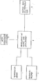
- the block diagram shows schematically an inventive control device for the control of a heat generator (oil-fired boiler) in a house.
- the control device 2 is connected to the power supply network 5 of the building.
- control unit 2 there is a transformer and a counting unit with time outputs (e.g. 5.4 0 , 8o min).
- the temperature sensor 1 reports to the control device 2 whether the set temperature (in this case the outside air temperature) is below or exceeded. If the temperature is exceeded (in the case of refrigeration systems, the temperature falls below), the control device 2 switches off the heat generator 3 for a certain time (for example 5, 4o or 8o min.). The heat generator 3 cannot start up due to its operating control devices. If the temperature sensor 1 feels after the set time (e.g. 5, 4o or 8o min.) That the set temperature is still exceeded, the energy tester 4 checks whether the heat consumer (e.g. space heating flow) requires energy.
- the set temperature in this case the outside air temperature
- the control device 2 switches off the heat generator 3 for a certain time (for example 5, 4o or 8o min.).
- the heat generator 3 cannot start up due to its operating control devices. If the temperature sensor 1
- the heat generator is put into operation or ready for operation, the energy tester 4 continuously checking whether the heat consumer still requires energy. If a little additional energy is required, if the temperature sensor 1 reports that the set temperature has still been exceeded, the heat generator 3 is put out of operation again for the set time. If the temperature sensor 1 reports that the set temperature has fallen below, the system is put back into operation or ready for operation regardless of whether the set time has expired. However, this only takes place when the energy tester 4 reports for the first time that the heat consumer needs energy.
Landscapes
- Engineering & Computer Science (AREA)
- Chemical & Material Sciences (AREA)
- Combustion & Propulsion (AREA)
- Mechanical Engineering (AREA)
- General Engineering & Computer Science (AREA)
- Control Of Temperature (AREA)
- Air Conditioning Control Device (AREA)
Abstract
Description
- Die Erfindung betrifft eine Regeleinrichtung für Heizungs-oder Kälteanlagen bestehend aus einem Regelgerät, mindestens einem Temperaturgeber z.B. Außenfühler, mindestens einem Energieprüfer z.B. Thermostat oder Ventilendschalter und mindestens einem Wärme- oder Kälteerzeuger.
- Regeleinrichtungen zur Steuerung von Heizungs- und Kälteanlagen sind in den verschiedensten Ausführungen bereits bekannt. Die DE-OS 2.527.2oo zeigt eine Regeleinrichtung für Verdampfungsbrenner durch die die Bimetall Heizwicklung des Ölreglers und die Erregerwicklung des Magnetventiles gegenüber der Zündstabanspeisung zeitverzögert an die Netzspannung anschaltbar ist.
- Aus der DE-AS 2.226.865 ist eine Regeleinrichtung bekannt, die mit zwei Thermogrenzwertschaltern, die unterschiedlich eingestellt sind, einen Umlaufwasserheizer und eine Umwälzpumpe schaltet.
- Die erfindungsgemäße Regeleinrichtung hat sich nun zur Aufgabe gestellt, nach dem Überschreiten einer Bezugstemperatur, die vom Temperaturgeber gefühlt und am Regelgerät eingestellt ist, den Wärme- oder Kälteerzeuger für eine, im Regelgerät eingestellte Abschaltzeit, unabhängig von der Heiz- oder Kältekreisregelung, abzuschalten und nach Ablauf der Abschaltzeit und dem Einschalten des Energieprüfers während dieser Abschaltzeit, den Wärme- oder Kälteerzeuger für eine, ebenfalls im Regelgerät eingestellte Einschaltzeit freizugeben.
- Die im Regelgerät eingestellte Abschaltzeit soll sich um eine Periode verlängern,wenn sich der Energieprüfer in der vorhergehenden Abschaltzeit nicht einschaltet.
- Die im Regelgerät eingestellte Einschaltzeit wird um eine Periode verlängert, wenn der Energieprüfer in der vorhergehenden Einschaltzeit nicht abschaltet.
- Beim Unterschreiten einer Bezugstemperatur, die vom Temperaturgeber gefühlt und im Regelgerät eingestellt ist, soll der Wärme-oder Kälteerzeuger erst in Betrieb gehen, wenn der Energieprüfer einschaltet.
- Nachstehend wird nun die Erfindung an Hand der Zeichnung, näher beschrieben, ohne jedoch darauf beschränkt zu sein.
- Das Blockschaltbild zeigt schematisch ein erfindungsgemäßes Regelgerät für die Steuerung eines Wärmeerzeugers (ölbefeuerter Heizkessel) in einem Wohnhaus.
- Das Regelgerät 2 ist an das Stromversorgungsnetz 5 des Gebäudes angeschlossen. Im Regelgerät 2 befindet sich ein Transformator und eine Zähleinheit mit Zeitausgängen (z.B. 5,40, 8o Min). Der Temperaturgeber 1 meldet an das Regelgerät 2, ob die eingestellte Temperatur (in diesem Fall die Außenlufttemperatur) unter- oder überschritten ist. Ist die Temperatur überschritten (bei Kälteanlagen Unterschritten) so schaltet das Regelgerät 2 für eine bestimmte Zeit (z.B. 5, 4o oder 8o Min.) den Wärmeerzeuger 3 ab. Der Wärmeerzeuger 3 kann sich durch seine Betriebsregelgeräte nicht in Betrieb setzen. Fühlt der Temperaturgeber 1, nach Ablauf der eingestellten Zeit (z.B. 5, 4o oder 8o Min.), daß die eingestellte Temperatur noch überschritten ist, so wird durch den Energieprüfer 4 kontrolliert, ob der Wärmeverbraucher (z.B. Raumheizungsvorlauf) Energie benötigt. Ist dies der Fall, so wird der Wärmeerzeuger in Betrieb bzw. Betriebsbereitschaft versetzt, wobei der Energieprüfer 4 laufend kontrolliert, ob der Wärmeverbraucher noch Energie benötigt. Wirdleine zusätzliche Energie mehr benötigt, so wird, falls der Temperaturgeber 1 meldet, daß die eingestellte Temperatur noch überschritten ist, der Wärmeerzeuger 3 wieder für die eingestellte Zeit außer Betrieb gesetzt. Meldet der Temperaturgeber 1, daß die eingestellte Temperatur unterschritten ist, so wird die Anlage, unabhängig ob die eingestellte Zeit abgelaufen ist, wieder in Betrieb bzw. Betriebsbereitschaft versetzt. Dies erfolgt jedoch erst, wenn der Energieprüfer 4 das erste Mal meldet, daß der Wärmeverbraucher Energie benötigt.
Claims (4)
Applications Claiming Priority (2)
| Application Number | Priority Date | Filing Date | Title |
|---|---|---|---|
| AT6193/78 | 1978-08-25 | ||
| AT619378A AT360204B (de) | 1978-08-25 | 1978-08-25 | Regeleinrichtung fuer heizungs- oder kaelte- anlagen |
Publications (2)
| Publication Number | Publication Date |
|---|---|
| EP0008461A1 true EP0008461A1 (de) | 1980-03-05 |
| EP0008461B1 EP0008461B1 (de) | 1983-04-20 |
Family
ID=3583823
Family Applications (1)
| Application Number | Title | Priority Date | Filing Date |
|---|---|---|---|
| EP19790103093 Expired EP0008461B1 (de) | 1978-08-25 | 1979-08-23 | Regeleinrichtung für Heizungs- oder Kälteanlagen |
Country Status (3)
| Country | Link |
|---|---|
| EP (1) | EP0008461B1 (de) |
| AT (1) | AT360204B (de) |
| DE (1) | DE2965249D1 (de) |
Cited By (2)
| Publication number | Priority date | Publication date | Assignee | Title |
|---|---|---|---|---|
| DE3145215A1 (de) * | 1980-11-14 | 1982-07-01 | Michael R. Ann Arbor Mich. Levine | Thermostateinrichtung |
| AT408583B (de) * | 1992-09-21 | 2002-01-25 | Vaillant Gmbh | Verfahren zur steuerung einer heizungsanlage |
Families Citing this family (1)
| Publication number | Priority date | Publication date | Assignee | Title |
|---|---|---|---|---|
| AT405449B (de) * | 1992-09-21 | 1999-08-25 | Vaillant Gmbh | Verfahren zum steuern einer heizungsanlage und vorrichtung zur durchführung des verfahrens |
Citations (6)
| Publication number | Priority date | Publication date | Assignee | Title |
|---|---|---|---|---|
| US2519266A (en) * | 1947-05-20 | 1950-08-15 | Robertshaw Fulton Controls Co | Temperature control apparatus |
| NL6919002A (de) * | 1968-12-26 | 1970-06-30 | ||
| DE2226865A1 (de) * | 1972-06-02 | 1973-12-06 | Vaillant Joh Kg | Regeleinrichtung fuer eine warmwasserheizungsanlage |
| NL7507345A (nl) * | 1974-06-19 | 1975-12-23 | Ferdinand Karpf | Automatische regelinrichting voor een met een ver- dampingsbrander uitgeruste verwarmingsinstallatie, zoals een centrale verwarmingsinstallatie of een oliebranderinstallatie. |
| US3964676A (en) * | 1974-09-30 | 1976-06-22 | Albert H. Rooks | Electronic morning start-up control for a building temperature control system |
| GB1537050A (en) * | 1976-11-24 | 1978-12-29 | Andrews Weatherfoil Ltd | Controller units for central heating systems |
-
1978
- 1978-08-25 AT AT619378A patent/AT360204B/de not_active IP Right Cessation
-
1979
- 1979-08-23 EP EP19790103093 patent/EP0008461B1/de not_active Expired
- 1979-08-23 DE DE7979103093T patent/DE2965249D1/de not_active Expired
Patent Citations (7)
| Publication number | Priority date | Publication date | Assignee | Title |
|---|---|---|---|---|
| US2519266A (en) * | 1947-05-20 | 1950-08-15 | Robertshaw Fulton Controls Co | Temperature control apparatus |
| NL6919002A (de) * | 1968-12-26 | 1970-06-30 | ||
| DE2226865A1 (de) * | 1972-06-02 | 1973-12-06 | Vaillant Joh Kg | Regeleinrichtung fuer eine warmwasserheizungsanlage |
| NL7507345A (nl) * | 1974-06-19 | 1975-12-23 | Ferdinand Karpf | Automatische regelinrichting voor een met een ver- dampingsbrander uitgeruste verwarmingsinstallatie, zoals een centrale verwarmingsinstallatie of een oliebranderinstallatie. |
| DE2527200A1 (de) * | 1974-06-19 | 1976-01-08 | Ferdinand Karpf | Vollautomatische regelungseinrichtung fuer heizgeraete mit verdampfungsbrenner, wie zentralheizungskessel oder oeloefen |
| US3964676A (en) * | 1974-09-30 | 1976-06-22 | Albert H. Rooks | Electronic morning start-up control for a building temperature control system |
| GB1537050A (en) * | 1976-11-24 | 1978-12-29 | Andrews Weatherfoil Ltd | Controller units for central heating systems |
Cited By (2)
| Publication number | Priority date | Publication date | Assignee | Title |
|---|---|---|---|---|
| DE3145215A1 (de) * | 1980-11-14 | 1982-07-01 | Michael R. Ann Arbor Mich. Levine | Thermostateinrichtung |
| AT408583B (de) * | 1992-09-21 | 2002-01-25 | Vaillant Gmbh | Verfahren zur steuerung einer heizungsanlage |
Also Published As
| Publication number | Publication date |
|---|---|
| DE2965249D1 (en) | 1983-05-26 |
| EP0008461B1 (de) | 1983-04-20 |
| AT360204B (de) | 1980-12-29 |
| ATA619378A (de) | 1979-11-15 |
Similar Documents
| Publication | Publication Date | Title |
|---|---|---|
| DE3145215A1 (de) | Thermostateinrichtung | |
| US4046532A (en) | Refrigeration load shedding control device | |
| US4703795A (en) | Control system to delay the operation of a refrigeration heat pump apparatus after the operation of a furnace is terminated | |
| US4485966A (en) | Pulsation device for a heating or cooling unit | |
| US2331476A (en) | Control system for heating devices | |
| EP0008461B1 (de) | Regeleinrichtung für Heizungs- oder Kälteanlagen | |
| EP0119313A2 (de) | Verfahren und Vorrichtung zur Einzelraumtemperaturregelung | |
| DE2539371A1 (de) | Thermostatventil fuer heizkoerper | |
| EP0192226B1 (de) | Verfahren zur Regelung der Temperatur in Räumen, die Heiz- oder Kühleinrichtungen mit Thermostatventilen aufweisen | |
| DE19601517A1 (de) | Regelung eines Gasheizgeräts | |
| EP0229319A2 (de) | Warmwasser-Heizungsanlage mit Wärmeverbrauchsmesser | |
| US2801826A (en) | Control apparatus | |
| AT202656B (de) | Schaltung zur Steuerung eines Mehrstufenmotors, insbesonders Vierstufenmotors für die Zufuhr der Verbrennungsluft bei Warmwasser- bzw. Dampfkesseln | |
| US2767922A (en) | Means for limiting furnace temperature in accordance with heat requirement | |
| US4046531A (en) | Refrigeration load shedding control device | |
| EP0036567B1 (de) | Steuereinrichtung für einen Umlaufwasserheizer | |
| US3028093A (en) | Multiple interlock control circuit for plural furnace units | |
| DE691232C (de) | Einrichtung zur temperaturabhaengigen Ein- und Ausschaltung der Energiequelle einer Kaeltemaschine | |
| AT297163B (de) | Aufladesteuerung für elektrische Speicherheizungen | |
| US2036868A (en) | Temperature control system | |
| AT263982B (de) | Ölheizungsanlage mit Verdampfungsbrenner | |
| DE710792C (de) | Selbsttaetig arbeitender Temperaturregler fuer Heizungsanlagen | |
| AT155166B (de) | Verfahren zum Regeln der mittleren Raumtemperatur in Warmwasserheizanlagen, vorzugsweise mit Kohlenbeheizung. | |
| DE2610516A1 (de) | Verfahren und anlage zum heizen von raeumen eines gebaeudes o.dgl. | |
| SU1173048A1 (ru) | Система автоматического регулировани теплофикационной турбоустановки |
Legal Events
| Date | Code | Title | Description |
|---|---|---|---|
| PUAI | Public reference made under article 153(3) epc to a published international application that has entered the european phase |
Free format text: ORIGINAL CODE: 0009012 |
|
| AK | Designated contracting states |
Designated state(s): BE CH DE FR GB IT NL SE |
|
| 17P | Request for examination filed | ||
| ITF | It: translation for a ep patent filed | ||
| GRAA | (expected) grant |
Free format text: ORIGINAL CODE: 0009210 |
|
| AK | Designated contracting states |
Designated state(s): BE CH DE FR GB IT NL SE |
|
| REF | Corresponds to: |
Ref document number: 2965249 Country of ref document: DE Date of ref document: 19830526 |
|
| ET | Fr: translation filed | ||
| PGFP | Annual fee paid to national office [announced via postgrant information from national office to epo] |
Ref country code: CH Payment date: 19841019 Year of fee payment: 6 |
|
| REG | Reference to a national code |
Ref country code: CH Ref legal event code: PL |
|
| REG | Reference to a national code |
Ref country code: FR Ref legal event code: ST |
|
| REG | Reference to a national code |
Ref country code: FR Ref legal event code: AR |
|
| REG | Reference to a national code |
Ref country code: FR Ref legal event code: DA |
|
| PG25 | Lapsed in a contracting state [announced via postgrant information from national office to epo] |
Ref country code: CH Free format text: LAPSE BECAUSE OF NON-PAYMENT OF DUE FEES Effective date: 19890831 |
|
| ITTA | It: last paid annual fee | ||
| PGFP | Annual fee paid to national office [announced via postgrant information from national office to epo] |
Ref country code: DE Payment date: 19940609 Year of fee payment: 16 |
|
| PGFP | Annual fee paid to national office [announced via postgrant information from national office to epo] |
Ref country code: GB Payment date: 19940610 Year of fee payment: 16 |
|
| PGFP | Annual fee paid to national office [announced via postgrant information from national office to epo] |
Ref country code: NL Payment date: 19940831 Year of fee payment: 16 |
|
| EAL | Se: european patent in force in sweden |
Ref document number: 79103093.5 |
|
| PGFP | Annual fee paid to national office [announced via postgrant information from national office to epo] |
Ref country code: FR Payment date: 19950614 Year of fee payment: 17 |
|
| PGFP | Annual fee paid to national office [announced via postgrant information from national office to epo] |
Ref country code: SE Payment date: 19950615 Year of fee payment: 17 |
|
| PGFP | Annual fee paid to national office [announced via postgrant information from national office to epo] |
Ref country code: BE Payment date: 19950706 Year of fee payment: 17 |
|
| PG25 | Lapsed in a contracting state [announced via postgrant information from national office to epo] |
Ref country code: GB Effective date: 19950823 |
|
| PG25 | Lapsed in a contracting state [announced via postgrant information from national office to epo] |
Ref country code: NL Effective date: 19960301 |
|
| GBPC | Gb: european patent ceased through non-payment of renewal fee |
Effective date: 19950823 |
|
| NLV4 | Nl: lapsed or anulled due to non-payment of the annual fee |
Effective date: 19960301 |
|
| PG25 | Lapsed in a contracting state [announced via postgrant information from national office to epo] |
Ref country code: DE Effective date: 19960501 |
|
| PG25 | Lapsed in a contracting state [announced via postgrant information from national office to epo] |
Ref country code: SE Effective date: 19960824 |
|
| PG25 | Lapsed in a contracting state [announced via postgrant information from national office to epo] |
Ref country code: BE Effective date: 19960831 |
|
| BERE | Be: lapsed |
Owner name: HOLZTRATTNER HEINRICH Effective date: 19960831 |
|
| PG25 | Lapsed in a contracting state [announced via postgrant information from national office to epo] |
Ref country code: FR Effective date: 19970430 |
|
| EUG | Se: european patent has lapsed |
Ref document number: 79103093.5 |
|
| REG | Reference to a national code |
Ref country code: FR Ref legal event code: ST |
|
| PLBE | No opposition filed within time limit |
Free format text: ORIGINAL CODE: 0009261 |
|
| STAA | Information on the status of an ep patent application or granted ep patent |
Free format text: STATUS: NO OPPOSITION FILED WITHIN TIME LIMIT |