EP0008523A2 - Systèmes de commande hydraulique - Google Patents
Systèmes de commande hydraulique Download PDFInfo
- Publication number
- EP0008523A2 EP0008523A2 EP79301667A EP79301667A EP0008523A2 EP 0008523 A2 EP0008523 A2 EP 0008523A2 EP 79301667 A EP79301667 A EP 79301667A EP 79301667 A EP79301667 A EP 79301667A EP 0008523 A2 EP0008523 A2 EP 0008523A2
- Authority
- EP
- European Patent Office
- Prior art keywords
- pressure
- load
- control valve
- spool
- flow
- Prior art date
- Legal status (The legal status is an assumption and is not a legal conclusion. Google has not performed a legal analysis and makes no representation as to the accuracy of the status listed.)
- Granted
Links
Images



Classifications
-
- F—MECHANICAL ENGINEERING; LIGHTING; HEATING; WEAPONS; BLASTING
- F15—FLUID-PRESSURE ACTUATORS; HYDRAULICS OR PNEUMATICS IN GENERAL
- F15B—SYSTEMS ACTING BY MEANS OF FLUIDS IN GENERAL; FLUID-PRESSURE ACTUATORS, e.g. SERVOMOTORS; DETAILS OF FLUID-PRESSURE SYSTEMS, NOT OTHERWISE PROVIDED FOR
- F15B11/00—Servomotor systems without provision for follow-up action; Circuits therefor
- F15B11/02—Systems essentially incorporating special features for controlling the speed or actuating force of an output member
- F15B11/04—Systems essentially incorporating special features for controlling the speed or actuating force of an output member for controlling the speed
- F15B11/05—Systems essentially incorporating special features for controlling the speed or actuating force of an output member for controlling the speed specially adapted to maintain constant speed, e.g. pressure-compensated, load-responsive
-
- E—FIXED CONSTRUCTIONS
- E02—HYDRAULIC ENGINEERING; FOUNDATIONS; SOIL SHIFTING
- E02F—DREDGING; SOIL-SHIFTING
- E02F9/00—Component parts of dredgers or soil-shifting machines, not restricted to one of the kinds covered by groups E02F3/00 - E02F7/00
- E02F9/20—Drives; Control devices
- E02F9/22—Hydraulic or pneumatic drives
- E02F9/2221—Control of flow rate; Load sensing arrangements
- E02F9/2225—Control of flow rate; Load sensing arrangements using pressure-compensating valves
-
- F—MECHANICAL ENGINEERING; LIGHTING; HEATING; WEAPONS; BLASTING
- F15—FLUID-PRESSURE ACTUATORS; HYDRAULICS OR PNEUMATICS IN GENERAL
- F15B—SYSTEMS ACTING BY MEANS OF FLUIDS IN GENERAL; FLUID-PRESSURE ACTUATORS, e.g. SERVOMOTORS; DETAILS OF FLUID-PRESSURE SYSTEMS, NOT OTHERWISE PROVIDED FOR
- F15B13/00—Details of servomotor systems ; Valves for servomotor systems
- F15B13/02—Fluid distribution or supply devices characterised by their adaptation to the control of servomotors
- F15B13/04—Fluid distribution or supply devices characterised by their adaptation to the control of servomotors for use with a single servomotor
- F15B13/0416—Fluid distribution or supply devices characterised by their adaptation to the control of servomotors for use with a single servomotor with means or adapted for load sensing
- F15B13/0417—Load sensing elements; Internal fluid connections therefor; Anti-saturation or pressure-compensation valves
-
- F—MECHANICAL ENGINEERING; LIGHTING; HEATING; WEAPONS; BLASTING
- F15—FLUID-PRESSURE ACTUATORS; HYDRAULICS OR PNEUMATICS IN GENERAL
- F15B—SYSTEMS ACTING BY MEANS OF FLUIDS IN GENERAL; FLUID-PRESSURE ACTUATORS, e.g. SERVOMOTORS; DETAILS OF FLUID-PRESSURE SYSTEMS, NOT OTHERWISE PROVIDED FOR
- F15B2211/00—Circuits for servomotor systems
- F15B2211/30—Directional control
- F15B2211/305—Directional control characterised by the type of valves
- F15B2211/30525—Directional control valves, e.g. 4/3-directional control valve
- F15B2211/3053—In combination with a pressure compensating valve
- F15B2211/3055—In combination with a pressure compensating valve the pressure compensating valve is arranged between directional control valve and return line
-
- F—MECHANICAL ENGINEERING; LIGHTING; HEATING; WEAPONS; BLASTING
- F15—FLUID-PRESSURE ACTUATORS; HYDRAULICS OR PNEUMATICS IN GENERAL
- F15B—SYSTEMS ACTING BY MEANS OF FLUIDS IN GENERAL; FLUID-PRESSURE ACTUATORS, e.g. SERVOMOTORS; DETAILS OF FLUID-PRESSURE SYSTEMS, NOT OTHERWISE PROVIDED FOR
- F15B2211/00—Circuits for servomotor systems
- F15B2211/30—Directional control
- F15B2211/32—Directional control characterised by the type of actuation
- F15B2211/329—Directional control characterised by the type of actuation actuated by fluid pressure
-
- F—MECHANICAL ENGINEERING; LIGHTING; HEATING; WEAPONS; BLASTING
- F15—FLUID-PRESSURE ACTUATORS; HYDRAULICS OR PNEUMATICS IN GENERAL
- F15B—SYSTEMS ACTING BY MEANS OF FLUIDS IN GENERAL; FLUID-PRESSURE ACTUATORS, e.g. SERVOMOTORS; DETAILS OF FLUID-PRESSURE SYSTEMS, NOT OTHERWISE PROVIDED FOR
- F15B2211/00—Circuits for servomotor systems
- F15B2211/30—Directional control
- F15B2211/35—Directional control combined with flow control
- F15B2211/353—Flow control by regulating means in return line, i.e. meter-out control
-
- F—MECHANICAL ENGINEERING; LIGHTING; HEATING; WEAPONS; BLASTING
- F15—FLUID-PRESSURE ACTUATORS; HYDRAULICS OR PNEUMATICS IN GENERAL
- F15B—SYSTEMS ACTING BY MEANS OF FLUIDS IN GENERAL; FLUID-PRESSURE ACTUATORS, e.g. SERVOMOTORS; DETAILS OF FLUID-PRESSURE SYSTEMS, NOT OTHERWISE PROVIDED FOR
- F15B2211/00—Circuits for servomotor systems
- F15B2211/40—Flow control
- F15B2211/405—Flow control characterised by the type of flow control means or valve
- F15B2211/40553—Flow control characterised by the type of flow control means or valve with pressure compensating valves
- F15B2211/40569—Flow control characterised by the type of flow control means or valve with pressure compensating valves the pressure compensating valve arranged downstream of the flow control means
-
- F—MECHANICAL ENGINEERING; LIGHTING; HEATING; WEAPONS; BLASTING
- F15—FLUID-PRESSURE ACTUATORS; HYDRAULICS OR PNEUMATICS IN GENERAL
- F15B—SYSTEMS ACTING BY MEANS OF FLUIDS IN GENERAL; FLUID-PRESSURE ACTUATORS, e.g. SERVOMOTORS; DETAILS OF FLUID-PRESSURE SYSTEMS, NOT OTHERWISE PROVIDED FOR
- F15B2211/00—Circuits for servomotor systems
- F15B2211/50—Pressure control
- F15B2211/505—Pressure control characterised by the type of pressure control means
- F15B2211/50509—Pressure control characterised by the type of pressure control means the pressure control means controlling a pressure upstream of the pressure control means
- F15B2211/50536—Pressure control characterised by the type of pressure control means the pressure control means controlling a pressure upstream of the pressure control means using unloading valves controlling the supply pressure by diverting fluid to the return line
-
- F—MECHANICAL ENGINEERING; LIGHTING; HEATING; WEAPONS; BLASTING
- F15—FLUID-PRESSURE ACTUATORS; HYDRAULICS OR PNEUMATICS IN GENERAL
- F15B—SYSTEMS ACTING BY MEANS OF FLUIDS IN GENERAL; FLUID-PRESSURE ACTUATORS, e.g. SERVOMOTORS; DETAILS OF FLUID-PRESSURE SYSTEMS, NOT OTHERWISE PROVIDED FOR
- F15B2211/00—Circuits for servomotor systems
- F15B2211/50—Pressure control
- F15B2211/515—Pressure control characterised by the connections of the pressure control means in the circuit
- F15B2211/5157—Pressure control characterised by the connections of the pressure control means in the circuit being connected to a pressure source and a return line
-
- F—MECHANICAL ENGINEERING; LIGHTING; HEATING; WEAPONS; BLASTING
- F15—FLUID-PRESSURE ACTUATORS; HYDRAULICS OR PNEUMATICS IN GENERAL
- F15B—SYSTEMS ACTING BY MEANS OF FLUIDS IN GENERAL; FLUID-PRESSURE ACTUATORS, e.g. SERVOMOTORS; DETAILS OF FLUID-PRESSURE SYSTEMS, NOT OTHERWISE PROVIDED FOR
- F15B2211/00—Circuits for servomotor systems
- F15B2211/50—Pressure control
- F15B2211/52—Pressure control characterised by the type of actuation
- F15B2211/528—Pressure control characterised by the type of actuation actuated by fluid pressure
-
- Y—GENERAL TAGGING OF NEW TECHNOLOGICAL DEVELOPMENTS; GENERAL TAGGING OF CROSS-SECTIONAL TECHNOLOGIES SPANNING OVER SEVERAL SECTIONS OF THE IPC; TECHNICAL SUBJECTS COVERED BY FORMER USPC CROSS-REFERENCE ART COLLECTIONS [XRACs] AND DIGESTS
- Y10—TECHNICAL SUBJECTS COVERED BY FORMER USPC
- Y10T—TECHNICAL SUBJECTS COVERED BY FORMER US CLASSIFICATION
- Y10T137/00—Fluid handling
- Y10T137/8593—Systems
- Y10T137/87169—Supply and exhaust
- Y10T137/87177—With bypass
- Y10T137/87185—Controlled by supply or exhaust valve
-
- Y—GENERAL TAGGING OF NEW TECHNOLOGICAL DEVELOPMENTS; GENERAL TAGGING OF CROSS-SECTIONAL TECHNOLOGIES SPANNING OVER SEVERAL SECTIONS OF THE IPC; TECHNICAL SUBJECTS COVERED BY FORMER USPC CROSS-REFERENCE ART COLLECTIONS [XRACs] AND DIGESTS
- Y10—TECHNICAL SUBJECTS COVERED BY FORMER USPC
- Y10T—TECHNICAL SUBJECTS COVERED BY FORMER US CLASSIFICATION
- Y10T137/00—Fluid handling
- Y10T137/8593—Systems
- Y10T137/87169—Supply and exhaust
- Y10T137/87233—Biased exhaust valve
Definitions
- This invention relates to systems for controlling the operation of double-acting hydraulic rams or motors and which systems incorporate a directional control valve.
- Both open and closed centre hydraulic directional control valves are used in such systems and whilst directional control valves of the proportional meter-in type, i.e. which meter or regulate the flow of pressure fluid to the load (ram or motor), have been found to have many advantages, they only work satisfactorily with a rising or positive load and with a heavy falling or negative load they revert back to the characteristics of the standard open or closed centre valve, i.e. poor metering, high pressure drop and high flow forces.
- the object of the present invention is to provide a control system incorporating improved directional control means which have all the advantages of the proportional meter-in type directional control valve whilst avoiding the disadvantages normally associated therewith.
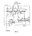
- a control system for the purpose mentioned includes a proportional meter-out type directional control valve which meters the flow of fluid out of the load and, in association therewith, a combined flow and pressure control valve in the return line from the load and which is responsive to the pressure drop across the meter-out orifice of the directional control valve such that return line flow is restricted at high pressure drops and the supply pressure to the load is increased at low pressure drops whereby there is obtained a substantially constant pressure drop across said meter-out orifice independent of the size or direction of the load.
- the directional control valve is a closed centre type of valve having two load ports and two return ports and arranged to connect one of the load ports with the supply pressure and one with one of the return ports when the spool is moved in either direction from the central closed or neutral position.
- the combined flow and pressure control valve comprises a spring-loaded spool controlling the restriction in the return line and connected to the control valve by pilot lines, preferably switched in response to displacement of the directional control valve spool, for applying the pressure downstream cf the meter-out orifice to act on the spool with the spring in apposition to the pressure upstream of the meter-out orifice.
- an unloader spool valve connected in the supply pressure line and also connected by a pilot pressure line to the combined flow and pressure control valve also controlling a restriction in the unloader pilot flow thereby to regulate the supply pressure.
- the pilot line 8 leading to the non spring end of a combined flow and pressure control valve 9 opens and the P to A port opens, connecting the pump to the load (ram or motor). Further movement closes the unloader switch port 6 and opens the B to R port, allowing oil to return from the load via the valve 9 to drain.
- the upstream pressure of the B to R metering orifice is fed via pilot lines 8 and 15 to the non spring end of the spool of valve 9 and the downstream pressure is transmitted to the spring end of said spool via pilot line 10.
- the unloader spool 1 regulates the supply pressure until a state of equilibrium is reached and the pressure drop across the unloader spool 1 is equal to the equivalent pressure of the unloader spring 7.
- the unloader spring 7 therefore maintains a fairly constant pressure drop across the unloader spool 1, and hence the unloader orifice 4, and the unloader pilot flow is therefore constant.
- orifice X is regulated by the pressure drop across the meter-out orifice B to R at low pressure drops, orifice X tends to close, thereby increasing the supply flow and pressure to the load, and hence the return flow from the load, until the B to R pressure drop is increased sufficiently to balance the spring load 11.
- orifice X tends to open, thereby decreasing the supply flow and pressure to the load and the return flow from the load, until the B to R pressure drop is again equal to the equivalent spring load 11.
- pilot line 12 to the non spring end of the valve 9 and the system operates as before, regulating return line flow from the load proportional to the size of the meter-out orifice A to R and independently of load size or direction.
- the system can also contain a pilot line relief valve 13, although this is not fundamental to the circuit, which sets a pressure limit on the unloader pilot flow at the spring end of the unloader spool 1. In so doing, a pressure limit is set on the supply pressure, since the pressure drop across the unloader is constant, as explained previously, and the pilot line relief valve, together with the unloader, forms a pilot-operated relief valve.
- pilot lines 8 and 12 which are used to transmit the upstream pressure of the selected meter-out orifice, to the non spring end of the control valve 9 can be selected by the spool 3 of the directional control valve in a number of different ways, the general requirements of the system being that the pilot lines must be sealed when the spool 3 is in neutral position to prevent service port leakage (not necessary if the load actuator is a motor with freewheel or if lock valves are fitted to the service lines A and B) and that the selected line must remain open regardless of load size or direction.
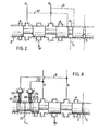
- a preferred system is shown in Figure 2 where pilot lines 8 and 12 transmit service port pressures to a pilot line switch port 14, situated on the spool 3.
- pilot line 8 or 12 When the spool 3 is selected, the appropriate pilot line 8 or 12 is connected to pilot line 15 which leads to the non-spring end of the control valve 9.
- This system has the advantage over that shown in Figure 1 that a shorter stroke of the spool 3 is required since the pilot lines 8 or 12 can be opened at the same time as the meter-out orifice is opened.
- pilot lines 8 and 12 are closed, when the main spool 3 is in neutral, by check valves 36 and 37. These are selectively opened by push rods 38 and 39 when the main spool 3 is selected to the right or to the left, by the mechanical action of the cam faces 40 and 41 on the main spool 3.
- the service port pressure is then transmitted via pilot line 15 to the non spring end of the combined flow and pressure control valve spool 9.
- pilot lines 8 and 12 are closed, when the spool 3 is in neutral by a 3-way spool valve 42. This is selected to open either pilot line 8 or pilot line 12 to pilot line 15 by the mechanical action of spring 46, push rod 43 and cam faces 44 or 45.
- pilot lines 8 and 12 are closed, when the main spool 3 is in neutral, by a 3-way spool valve 47. This. is selected to open either pilot line 8 or pilot line 12 to pilot line 15 by the pressure drop across an orifice 50 situated in the service line B.
- flow from the load creates a pressure drop across orifice 50, transmitted by pilot lines 51 and 52 to the ends of spool 47, sufficient to select spool 47 against spring load 49, and open pilot line 8 to pilot line 15.
- flow into the load creates a pressure drop across orifice 50 sufficient to select spool 47, against spring load 48, and open pilot line 12 to pilot line 15.
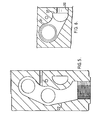
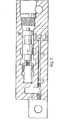
- the pressure drop created across the unload ⁇ r - orifice 4 is fed via passage 17, Figure 4, to the non spring end of the unloader spool 1 and via passages 22 and 24, Figures 4 and 7, to the spring end of the unloader spool 1, and is sufficient to open the unloader to the return line passage 22, thus allowing the pump flow to return to drain at low pressure.
- valve pilot switch is opened; further movement of the spool 3 opens passage 24 to passage 25 to allow oil to flow out of the load; and the unloader pilot switch 6 closes.
- the pressure in passage 24, i.e. upstream of the meter-out orifice, is fed via passage 8, through the open pilot switch 14 into passage 15, out of the valve block 19 and into the inlet block, Figure 4, at passage 29, to act on the non spring end of the valve spool 9.
- unloader pilot flow passes from passage 17, Figure 7, through the unloader orifice 4 and along passages 22 and 23 into chamber 35 in the valve spool 9, through orifice X, Figure 4, and into the return passage 22 and back to drain.
- the pressure drop across the unloader spool 1 is maintained constant by its unloader spring 7; the unloader spool, regulates the supply flow and pressure until the pressure at the non spring end of the unloader spool 1 is approximately equal to the equivalent pressure of the unloader spring 7 above the pressure at the spring end of the unloader spool 1.
- the pressure drop across the unloader orifice 4 is therefore fairly constant and the unloader pilot flow is also constant, as explained previously.
- the pressure drop across the control orifice X of the control valve 9 determines the pressure at the spring end of the unloader spool 1 and therefore the supply flow and pressure to the load.
- orifice Y With a rising load, i.e. one that pressurises the supply line to the load, at low pressure drops across the meter-out orifice, the opening of orifice Y may have no effect, but further movement of the spool of control valve 9 tends to close orifice X and hence increase the supply flow and pressure to the load. This in turn increases the return flow from the load, until the pressure drop across the meter-out orifice is equal to its equivalent spring load 11. At high pressure drops across the meter-out orifice, orifice X tends to open thus decreasing the supply flow and pressure, and hence the return line flow until the pressure drop across the meter-out orifice is again equal to its equivalent spring load.
- Orifice X in conjunction with the unloader spool 1, therefore, operates as a pressure control valve, regulating the supply flow and pressure to the load to maintain a constant pressure drop across the meter-out orifice.
- the unloader spool 1, Figure 4 can also be made to operate as a pilot-operated relief valve to protect the pump supply from over pressurisation by the addition of a small pilot relief valve 13 which limits the pressure at the spring end of the unloader spool 1.
- the pressure at the non spring end of the unloader spool 1 is therefore, also limited since a constant pressure drop exists over the unloader spool 1.
- a damping orifice 34 may be fitted to the spring end of the valve spool 9 to stabilize the spool against pump and load fluctuations, but it has no effect on the steady state operation of the system as described previously.
Landscapes
- Engineering & Computer Science (AREA)
- Physics & Mathematics (AREA)
- Fluid Mechanics (AREA)
- General Engineering & Computer Science (AREA)
- Mechanical Engineering (AREA)
- Mining & Mineral Resources (AREA)
- Civil Engineering (AREA)
- Structural Engineering (AREA)
- Fluid-Pressure Circuits (AREA)
Applications Claiming Priority (2)
| Application Number | Priority Date | Filing Date | Title |
|---|---|---|---|
| GB7834700 | 1978-08-25 | ||
| GB3470078 | 1978-08-25 |
Publications (3)
| Publication Number | Publication Date |
|---|---|
| EP0008523A2 true EP0008523A2 (fr) | 1980-03-05 |
| EP0008523A3 EP0008523A3 (en) | 1980-03-19 |
| EP0008523B1 EP0008523B1 (fr) | 1982-05-05 |
Family
ID=10499292
Family Applications (1)
| Application Number | Title | Priority Date | Filing Date |
|---|---|---|---|
| EP79301667A Expired EP0008523B1 (fr) | 1978-08-25 | 1979-08-15 | Systèmes de commande hydraulique |
Country Status (3)
| Country | Link |
|---|---|
| US (1) | US4275643A (fr) |
| EP (1) | EP0008523B1 (fr) |
| DE (1) | DE2962702D1 (fr) |
Cited By (8)
| Publication number | Priority date | Publication date | Assignee | Title |
|---|---|---|---|---|
| GB2121990A (en) * | 1982-06-15 | 1984-01-04 | William Richards Price | A hydraulic control system |
| DE3434014A1 (de) * | 1984-09-15 | 1986-03-20 | Beringer-Hydraulik GmbH, Neuheim, Zug | Hydraulische steuerung |
| EP0276221A4 (fr) * | 1986-07-21 | 1990-02-20 | Caterpillar Inc | Soupape de regulation compensee servant a reguler l'ecoulement d'un fluide. |
| EP0276222A4 (fr) * | 1986-07-21 | 1990-02-21 | Caterpillar Inc | Soupape de regulation compensee servant a reguler l'ecoulement d'un fluide. |
| EP0277946A4 (fr) * | 1986-07-21 | 1990-02-21 | Caterpillar Inc | Soupape de regulation compensee servant a reguler l'ecoulement d'un fluide. |
| EP0321475A4 (en) * | 1987-05-08 | 1991-11-06 | Caterpillar Inc. | Load responsive system having synchronizing systems between positive and negative load compensation |
| EP0298083A4 (en) * | 1986-12-22 | 1991-11-13 | Caterpillar Inc. | Load compensated valve |
| WO2015131918A1 (fr) * | 2014-03-01 | 2015-09-11 | Hydac Filtertechnik Gmbh | Système de soupape |
Families Citing this family (6)
| Publication number | Priority date | Publication date | Assignee | Title |
|---|---|---|---|---|
| US4503886A (en) * | 1983-05-12 | 1985-03-12 | Lockheed Corporation | Flow limiting selector valve |
| US4518320A (en) * | 1984-02-03 | 1985-05-21 | Deere & Company | Variable displacement pump system |
| US6082106A (en) * | 1997-10-17 | 2000-07-04 | Nachi-Fujikoshi Corp. | Hydraulic device |
| FI117571B (fi) * | 2005-02-23 | 2006-11-30 | John Deere Forestry Oy | Kompensointikytkentä moottorin ohjauksessa |
| US10216523B2 (en) | 2015-07-17 | 2019-02-26 | General Electric Company | Systems and methods for implementing control logic |
| DE202022100104U1 (de) | 2022-01-10 | 2023-04-17 | Dana Motion Systems Italia S.R.L. | Ventilanordnung und Hydraulikkreis |
Family Cites Families (7)
| Publication number | Priority date | Publication date | Assignee | Title |
|---|---|---|---|---|
| US2933105A (en) * | 1950-09-26 | 1960-04-19 | Borg Warner | Article handling and working apparatus |
| US3847180A (en) * | 1971-12-23 | 1974-11-12 | Caterpillar Tractor Co | Low effort, proportional control valve |
| GB1417606A (en) * | 1972-02-24 | 1975-12-10 | Daikin Ind Ltd | Fluid controlling apparatus |
| DE2230799A1 (de) * | 1972-06-23 | 1974-01-17 | Bosch Gmbh Robert | Steuervorrichtung fuer lastunabhaengige durchflussregulierung |
| GB1452609A (en) * | 1973-05-15 | 1976-10-13 | Sperry Rand Ltd | Hydraulic systems |
| US3998134A (en) * | 1974-11-08 | 1976-12-21 | Tadeusz Budzich | Load responsive fluid control valves |
| DE2519697A1 (de) * | 1975-05-02 | 1976-11-11 | Rexroth Gmbh G L | Mit einer zwei-wege-druckwaage kombiniertes vier-wegeventil |
-
1979
- 1979-08-15 EP EP79301667A patent/EP0008523B1/fr not_active Expired
- 1979-08-15 DE DE7979301667T patent/DE2962702D1/de not_active Expired
- 1979-08-24 US US06/069,536 patent/US4275643A/en not_active Expired - Lifetime
Cited By (8)
| Publication number | Priority date | Publication date | Assignee | Title |
|---|---|---|---|---|
| GB2121990A (en) * | 1982-06-15 | 1984-01-04 | William Richards Price | A hydraulic control system |
| DE3434014A1 (de) * | 1984-09-15 | 1986-03-20 | Beringer-Hydraulik GmbH, Neuheim, Zug | Hydraulische steuerung |
| EP0276221A4 (fr) * | 1986-07-21 | 1990-02-20 | Caterpillar Inc | Soupape de regulation compensee servant a reguler l'ecoulement d'un fluide. |
| EP0276222A4 (fr) * | 1986-07-21 | 1990-02-21 | Caterpillar Inc | Soupape de regulation compensee servant a reguler l'ecoulement d'un fluide. |
| EP0277946A4 (fr) * | 1986-07-21 | 1990-02-21 | Caterpillar Inc | Soupape de regulation compensee servant a reguler l'ecoulement d'un fluide. |
| EP0298083A4 (en) * | 1986-12-22 | 1991-11-13 | Caterpillar Inc. | Load compensated valve |
| EP0321475A4 (en) * | 1987-05-08 | 1991-11-06 | Caterpillar Inc. | Load responsive system having synchronizing systems between positive and negative load compensation |
| WO2015131918A1 (fr) * | 2014-03-01 | 2015-09-11 | Hydac Filtertechnik Gmbh | Système de soupape |
Also Published As
| Publication number | Publication date |
|---|---|
| DE2962702D1 (en) | 1982-06-24 |
| US4275643A (en) | 1981-06-30 |
| EP0008523A3 (en) | 1980-03-19 |
| EP0008523B1 (fr) | 1982-05-05 |
Similar Documents
| Publication | Publication Date | Title |
|---|---|---|
| US4020867A (en) | Multiple pressure compensated flow control valve device of parallel connection used with fixed displacement pump | |
| US3987622A (en) | Load controlled fluid system having parallel work elements | |
| US4112679A (en) | Load responsive fluid control valves | |
| EP0008523B1 (fr) | Systèmes de commande hydraulique | |
| US4082111A (en) | Load responsive fluid control valve | |
| US4253482A (en) | Hydraulic valve having pressure compensated demand flow | |
| CA1040061A (fr) | Systeme hydraulique pour vehicule de travail a dispositif regulateur/combinateur du fluide et des signaux | |
| US3979907A (en) | Priority control valve | |
| GB1425602A (en) | Directional control valves | |
| JPS6157482B2 (fr) | ||
| US4080994A (en) | Control arrangement for supplying pressure fluid to at least two hydraulically operated consumer devices | |
| USRE29538E (en) | Load responsive fluid control valve | |
| EP0111208A1 (fr) | Transmission de puissance | |
| US5156189A (en) | High flow control valve | |
| US3841096A (en) | Control and regulator device for a load-independent regulated hydraulic system | |
| US5433077A (en) | Actuator control device with meter-out valve | |
| US4408453A (en) | Hydraulic control system | |
| US3770007A (en) | Dual direction flow control valve | |
| US4089168A (en) | Load responsive fluid control valves | |
| US4362087A (en) | Fully compensated fluid control valve | |
| US4058139A (en) | Load responsive fluid control valves | |
| GB1560444A (en) | Load-responsive fluid power control system | |
| JPH0448969B2 (fr) | ||
| JPS6234963B2 (fr) | ||
| CA1056694A (fr) | Valves regulatrices de debit de fluide reagissant a la demande |
Legal Events
| Date | Code | Title | Description |
|---|---|---|---|
| PUAI | Public reference made under article 153(3) epc to a published international application that has entered the european phase |
Free format text: ORIGINAL CODE: 0009012 |
|
| PUAL | Search report despatched |
Free format text: ORIGINAL CODE: 0009013 |
|
| AK | Designated contracting states |
Designated state(s): DE GB SE |
|
| AK | Designated contracting states |
Designated state(s): DE GB SE |
|
| 17P | Request for examination filed | ||
| GRAA | (expected) grant |
Free format text: ORIGINAL CODE: 0009210 |
|
| AK | Designated contracting states |
Designated state(s): DE GB SE |
|
| REF | Corresponds to: |
Ref document number: 2962702 Country of ref document: DE Date of ref document: 19820624 |
|
| PGFP | Annual fee paid to national office [announced via postgrant information from national office to epo] |
Ref country code: GB Payment date: 19920804 Year of fee payment: 14 |
|
| PGFP | Annual fee paid to national office [announced via postgrant information from national office to epo] |
Ref country code: SE Payment date: 19920826 Year of fee payment: 14 |
|
| PGFP | Annual fee paid to national office [announced via postgrant information from national office to epo] |
Ref country code: DE Payment date: 19920827 Year of fee payment: 14 |
|
| PG25 | Lapsed in a contracting state [announced via postgrant information from national office to epo] |
Ref country code: GB Effective date: 19930815 |
|
| PG25 | Lapsed in a contracting state [announced via postgrant information from national office to epo] |
Ref country code: SE Effective date: 19930816 |
|
| GBPC | Gb: european patent ceased through non-payment of renewal fee |
Effective date: 19930815 |
|
| PG25 | Lapsed in a contracting state [announced via postgrant information from national office to epo] |
Ref country code: DE Effective date: 19940503 |
|
| EUG | Se: european patent has lapsed |
Ref document number: 79301667.6 Effective date: 19940310 |
|
| PLBE | No opposition filed within time limit |
Free format text: ORIGINAL CODE: 0009261 |
|
| STAA | Information on the status of an ep patent application or granted ep patent |
Free format text: STATUS: NO OPPOSITION FILED WITHIN TIME LIMIT |