EP0009639A2 - Structure de forage mobile polyvalente - Google Patents
Structure de forage mobile polyvalente Download PDFInfo
- Publication number
- EP0009639A2 EP0009639A2 EP79103264A EP79103264A EP0009639A2 EP 0009639 A2 EP0009639 A2 EP 0009639A2 EP 79103264 A EP79103264 A EP 79103264A EP 79103264 A EP79103264 A EP 79103264A EP 0009639 A2 EP0009639 A2 EP 0009639A2
- Authority
- EP
- European Patent Office
- Prior art keywords
- drill
- mast
- slide
- carrier
- pipe
- Prior art date
- Legal status (The legal status is an assumption and is not a legal conclusion. Google has not performed a legal analysis and makes no representation as to the accuracy of the status listed.)
- Withdrawn
Links
Images










Classifications
-
- E—FIXED CONSTRUCTIONS
- E21—EARTH OR ROCK DRILLING; MINING
- E21B—EARTH OR ROCK DRILLING; OBTAINING OIL, GAS, WATER, SOLUBLE OR MELTABLE MATERIALS OR A SLURRY OF MINERALS FROM WELLS
- E21B7/00—Special methods or apparatus for drilling
- E21B7/02—Drilling rigs characterised by means for land transport with their own drive, e.g. skid mounting or wheel mounting
- E21B7/027—Drills for drilling shallow holes, e.g. for taking soil samples or for drilling postholes
-
- E—FIXED CONSTRUCTIONS
- E21—EARTH OR ROCK DRILLING; MINING
- E21B—EARTH OR ROCK DRILLING; OBTAINING OIL, GAS, WATER, SOLUBLE OR MELTABLE MATERIALS OR A SLURRY OF MINERALS FROM WELLS
- E21B15/00—Supports for the drilling machine, e.g. derricks or masts
- E21B15/04—Supports for the drilling machine, e.g. derricks or masts specially adapted for directional drilling, e.g. slant hole rigs
-
- E—FIXED CONSTRUCTIONS
- E21—EARTH OR ROCK DRILLING; MINING
- E21B—EARTH OR ROCK DRILLING; OBTAINING OIL, GAS, WATER, SOLUBLE OR MELTABLE MATERIALS OR A SLURRY OF MINERALS FROM WELLS
- E21B19/00—Handling rods, casings, tubes or the like outside the borehole, e.g. in the derrick; Apparatus for feeding the rods or cables
- E21B19/02—Rod or cable suspensions
-
- E—FIXED CONSTRUCTIONS
- E21—EARTH OR ROCK DRILLING; MINING
- E21B—EARTH OR ROCK DRILLING; OBTAINING OIL, GAS, WATER, SOLUBLE OR MELTABLE MATERIALS OR A SLURRY OF MINERALS FROM WELLS
- E21B19/00—Handling rods, casings, tubes or the like outside the borehole, e.g. in the derrick; Apparatus for feeding the rods or cables
- E21B19/16—Connecting or disconnecting pipe couplings or joints
-
- E—FIXED CONSTRUCTIONS
- E21—EARTH OR ROCK DRILLING; MINING
- E21B—EARTH OR ROCK DRILLING; OBTAINING OIL, GAS, WATER, SOLUBLE OR MELTABLE MATERIALS OR A SLURRY OF MINERALS FROM WELLS
- E21B19/00—Handling rods, casings, tubes or the like outside the borehole, e.g. in the derrick; Apparatus for feeding the rods or cables
- E21B19/24—Guiding or centralising devices for drilling rods or pipes
-
- E—FIXED CONSTRUCTIONS
- E21—EARTH OR ROCK DRILLING; MINING
- E21B—EARTH OR ROCK DRILLING; OBTAINING OIL, GAS, WATER, SOLUBLE OR MELTABLE MATERIALS OR A SLURRY OF MINERALS FROM WELLS
- E21B3/00—Rotary drilling
- E21B3/02—Surface drives for rotary drilling
- E21B3/022—Top drives
Definitions
- the present invention relates to truck mounted mobile drilling rigs, and more particularly to an improved truck mounted mobile drilling rig which can be used with ! any of several drilling methods.
- the common mobile drilling rigs now in use mount a mast at the rear end of a large truck which may be retracted to lie horizontally or nearly horizontally over the truck, but which can be swung to an upright, vertical posi- ; tion for drilling.
- the truck will back up to align the drilling mast at the rear over a proposed or existing hole.
- the truck is then stabilized and leveled by suitable outriggers at each end of the truck.
- the drill rig truck will carry the machinery necessary to provide suitable power to compress air and to pump liquid as needed, depending upon the drilling equipment associated with the mast. If necessary, auxiliary vehicles can be used to carry extra compressors and the like.
- the drilling equipment carried on the truck can be of various types for different drilling methods.
- impact type drills will include pile drivers, air hammers and churning bits.
- Rotary type drills will include roller and fishtail bits attached to single and double wall drill stems, diamond bits and augers.
- Pile drivers are ordinarily used in overburden and unconsolidated sediments.
- Rotary drills are usually used for drilling wells.
- Diamond drills on different types of vehicles are used for obtaining hard rock core samples.
- Wagon drills carry jackhammers to drill in hard rock for setting explosives.
- Auger drills specialize in drilling holes and/or obtaining core samples in soil and overburden.
- the invention comprises, in essence, a multi-purpose mobile drill rig having a mast carried at the rear end of a truck which is shiftable from a horizontal retracted position over the truck to a vertical operative position for drilling. Also, this mast can drill at selected inclined positions if necessary.
- the mast carries a multi-purpose drill support which can carry any of several different types of drills including a pile driver, a rotary drive, a diamond drill and a jackhammer also called an air hammer.
- the drill rig may use air or water or a combination of both and it is capable of quickly shifting from one type of drilling method to another.
- objects of the present invention are to provide a novel and improved multi-purpose drill rig which is adapted for drilling by any one of several drilling methods; can quickly and easily shift from one drilling method to another without changing the set-up of the rig and without moving off the hole; can quickly and easily shift a drill out of alignment with the hole when other work is necessary such as setting casing or retrieving a drill stem; and which is an economical, rugged and durable unit.
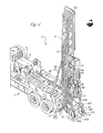
- an improved, mobile multiple purpose drilling rig R is mounted upon the frame of a truck T.
- the truck has lifting outriggers O at its front.
- Rear outriggers O 1 are attached to the frame of the drilling rig R.
- the drilling rig unit includes an elongated deck 30 which forms the bed of the truck and the drill rig mast 31 is at the rear end of this deck, that is, with respect to the rear of the truck. All other components forming the rig will, also be referred to as being forwardly and rearwardly, when necessary, with respect to the truck.
- An air compressor A, a hydraulic pump P and other components for operating the drill rig R are carried at the forward end and at the sides of the deck while the operators control console C is carried at the rear end of the deck alongside the mast 3l.
- the compressor A, the pump P, the engine, not shown, the operating components and the control console C are all conventional and need not be further described. Also, in the following description, it is to be noted that a number of other conventional parts and components, such as pressure lines to hydraulic cylinders are neither shown nor described.
- the drilling rig R includes the mast 31 to carry various types of drilling apparatus and this mast 31 is movably mounted for longitudinal slidable movements, verticle slidable movements and tipping movements.
- the mast may tip forwardly (with respect to the truck) from a vertical operating position to a near horizontal transport position over the truck T with the upper end of the mast resting upon strut supports S at the front end of the deck 30 as indicated in broken lines at Fig. 2.
- the mast 31 may also be operated at an inclined position as shown at Fig. 6.
- the mast is slidably affixed to a mast slide 32 at the forward face of the mast 31. Movement of the mast 31 along this mast slide 32 is controlled by hydraulic cylinders 33, best shown at Figs. 2 and 6.
- the base of the mast slide 32 is pivotally connected to the rear end of a deck slide 34 to permit the mast slide 32 and its mast 31 to be tipped forwardly from a vertical position and over the deck slide 34.
- This tipping movement is controlled by hydraulic cylinders 35, connecting with the front of the deck slide and with the top of the mast slide.
- the deck slide 34 is mounted upon horizontal, longitudinally-disposed, opposing guideways 36 at the rear section of the deck 30.
- a cylinder means is connected to the underside of the deck slide 34 and to the deck 30 to shift the deck slide forwardly and rearwardly on the deck.
- a slide frame 40 is slidably mounted between the elongated structural cords, a slide means, at the rear of the mast, and the slide frame supports a carrier 41 wherein a drilling mechanism is mounted.
- the carrier 41 is shiftably connected to the slide frame 40 by parallelogram linkages 42, a shifting means, to normally extend rearwardly from the mast but to swing inwardly . against the slide frame and within the embrace of the slide frame and partially into the mast.
- This longitudinal swinging movement is effected by diagonally placed cylinders 43 connecting with the slide 40 and carrier 41 and such movement provides a quick shift of the drilling mechanism whenever pipe pulling operations or the like are under way as with the aid of a pipe handling crown block 44 at the top of the mast.
- the slide frame 40 is connected with lifter-pulldown cables 45 extending from the top to the bottom of the mast 31 to forcibly raise and lower drilling.
- mechanisms mounted on the carrier 41 as shown at Fig. 2.
- a compound drum hoist 46 is mounted on the mast slide 32 to operate the boom at the top of the mast and the lifter-pulldown cables 45 as shown at Fig. 2.
- a suitable ground shoe 47 or 47a having a pipe passageway 48 or 48a through it will be connected to the base of the mast 31 and the mast will be lowered to place the shoe 47 or 47a onto the ground.
- the ground shoe 47 will outstand rearwardly from the mast with its center opening 48 in alignment with a drill stem depending from the drilling mechanism thereabove.
- the ground shoe 47 will include a breakout means within it to grip the drill stem, and to break and unwind drill stem joints as hereinafter described.
- the ground shoe 47a for a pile drive drilling mechanism, will include a pipe pulling means as hereinafter described.
- One or several drilling mechanisms may be mounted upon the carrier 41 for providing a variety of drilling modes and methods including pile driving, rotary well drilling, diamond drilling and jackhammer drilling.
- a selected method may be set up for a given drilling operation which will include several or all of the above mentioned drilling mechanisms.
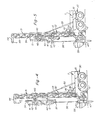
- a diesel pile driving hammer 50 is mounted in the carrier 4l and a ground shoe 47a is connected to the base of the mast 31.
- the diesel pile driving hammer 50 mounted in the carrier connects with a rigid thick-walled pipe 51 to drive it into the earth.
- the lower portion of the pile driving hammer is removed and the rotary drilling head 52 is mounted on the carrier and connected with a drill stem 53.
- the drill stem extends through a ground shoe 47 connected to the mast 3 1.
- a drive motor 54 at the top of this carrier 41 connects with the drilling head as shown.
- a lower portion of the pile driving hammer 51 is removed and a diamond drilling rotary head 54 is mounted on the carrier and is connected to a drill rod 56o
- the diamond drill head also connects with the drive motor 54.
- Fig. 5 shows the pile driving hammer 50 in place and a jackhammer 57 mounted on the outer face of the carrier 4l and connected with drill steel 58.
- the carrier is shifted into its support slide 40 to align the jackhammer steel 58 with the drill alignment of the other drilling mechanisms which are used with the carrier 41 at its rearwardly extended position.
- Fig. 6 the same arrangement is used as that shown at Fig. 5 but the mast 31 is tipped to a 45-degree inclination to illustrate the ease at which an inclined hole may be drilled.
- the only addition is a truncated ground engaging wedge 49 at the underside of the ground shoe 47 to provide good ground contact by the mast 31.
- the mast 31 is shifted on the mast slide 32 and by the deck slide to place the base of the mast against the ground and to pull it closely adjacent to the rear end of the deck 30.
- a solid pile or a thick-walled pipe is preferred with the pile driver. It may also be used to drive casing into overburden or into.a hole drilled by the rotary drill.
- a standard tubular drill string can be used with the rotary drilling head 50.
- a dual wall pipe, reverse circulation drilling system is ideal for the rotary drilling head 50 and is especially useful for soil sampling and mineral exploration. This is possible with a simple adaptor as hereinafter described.
- the piles, pipe tubes and steel rods used for drilling may collectively be referred to as "drill pipe means".
- This improved drill rig R is manifest and it is contemplated that drilling may proceed with both water and air as suitable drilling fluids depending upon the type of bit being used.
- An auxiliary piece of equipment will be a cyclone 59 to separate and/or control the discharge of cuttings.
- many of the components making up the drill rig R are conventional and need not be described; however, other components mentioned above will now be described in further detail.
- the Vehicle Deck 30 The Vehicle Deck 30
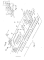
- the deck 30, which is mounted upon the bed frame of the trunk T, comprises a flat, horizontally disposed deck plate 60 having a peripheral flange 61 to provide a retainer lip to better hold items thereon.
- the deck plate is reinforced by a structural frame at its underside which is not shown and has a longitudinal central row of openings 62, 63, 64 and 65 and the longitudinal guideways 36 which carry the deck slide 34 are positioned at opposite sides of the rearward openings 64 and 65.
- the guideways are L shaped members having spacer flanges 66 upstanding from the deck plate 60 and outwardly extending guide flanges 67 at the top of the spacer flanges.
- the spacing between the guide flanges 67 and the deck plate surface defines laterally, outwardly-facing grooves 68.
- Other components which are attached to the deck will include a deck cover plate, sliding brackets and end plates, all of which are generally indicated as 69.
- a suitable bracket means, not shown, will be attached to the deck and to a cylinder means, also not shown, for moving the deck slide 34 along the guideways 360
- the deck slide 34 comprises a rectangular flat slide plate 70 which is connectively mounted upon the guideways 36 of the deck 30 for longitudinal movement thereon.
- the width of the plate 70 is slightly greater than the spacing of the opposing guideways 36 and an opposing, mating guideway is formed at the underside of, and at each side edge of the plate 70.
- Each guideway 71 is L shaped and is formed by bolting a spacer strip 72 and a flange strip 73 to the underside of the plate 70 to a mesh with the strips 66 and 67 of the respective guideway 36 as best shown at Fig. 10.
- Yoke brackets 74 are affixed to the underside of the slide plate 70 and are connected to the cylinder, heretofore mentioned but not shown, which will forcibly shift the deck slide 34 forwardly and rearwardly along the guideways 36 of the deck 30.
- a first pair of laterally spaced, upwardly extending pivot mount brackets 75 are affixed to the front end portion of the slide plate 70. These brackets connect with the lower ends of the hydraulic cylinders 35 as with pins 76. The cylinders 35 also connect with the mast slide 32 to raise and lower the mast slide 32 and the mast 31 as heretofore described.
- a second pair of laterally spaced upwardly extending pivot mount brackets 77 are affixed to the rear end portion of the slide plate 70 for pivot connection with the lower end of the mast slide 32, as with pins 78.
- the mast slide and the mast 31 will swing about the pivots of the brackets 77 as from a vertical position to a nearly horizontal position over the truck and upon the strut supports S at the front of the deck 30. Accordingly, the brackets 77 must extend upwardly above the slide plate 70 a distance sufficient to hold the lowered mast above equipment on the deck. This distance will be several feet and accordingly, the brackets 77 are reinforced with suitable cross struts 79.
- the mast slide 32 comprises a rectangular carrier plate 80 which is pivotally connected to the pivot mount brackets 77 of the deck slide 34 to swing from a vertical position to a nearly horizontal position as heretofore mentioned. Describing the mast slide as in its vertical position, a first pair of laterally spaced, forwardly outstanding pivot mount brackets 81 are affixed to the upper end of the plate 80 for pivotal connection with the upper ends of the power cylinders 35. The brackets 81 connect with the cylinders 35 as with pins 82.
- a second pair of laterally spaced, forwardly outstanding pivot mount brackets 83 are affixed to the lower end portion of the plate 80 for pivotal connection with the rearwardly upstanding pivot mount brackets 77 of the deck slide 34 as with pins 78, heretofore described.
- a pair of outwardly opposing guideways 84 are located near the side edges of the rear face of the carrier plate 80.
- Each guideway is an L shaped member formed by a spacer strip 85 and a flange strip 86 bolted to the plate as shown at Fig. 12.
- the cylinders 33 which shift the mast on the slide, are connected to a transverse shelf plate 87 located at the top of the front face of the carrier plate 80.
- the shelf plate merges with and is reinforced by the brackets 81 and a pair of passage holes 88 are located in this shelf plate 87 through which the pistons of cylinders 33 extend when the cylinders are bolted to the shelf plate.
- a pair of mounting blocks 89 are provided at the center, lower portion of the forward face of plate 80, with one being above the other.
- the drum hoist winch 46 is mounted upon these blocks 89.
- the mast 31 comprises an elongated framework, rectangular in section, having pairs of laterally spaced front and rear facing elongated cord members 90 and 91, respectively.
- the cord members are spaced and rigidly connected by bracing struts 92 at the forward face and at the sides of the mast, leaving the rearward face open to defined a slot means 93 wherein the slide frame 40 is mounted as heretofore mentioned.
- This mast 31 includes a slide bar 94 affixed to the forward edge of each front cord member 90, and each slide bar 94, located at the lower section of the mast, fits into a respective guideway 84 of the mast slide 32 as best shown at Fig. 12.
- the mast also includes a cross plate 95 which is transversly affixed to the forward edge of the forward cord members 90 at a suitable location above the slide bars 94.
- the cross plate 95 carries a pair of laterally spaced, forwardly extending pivot mount brackets 96 for connection with the piston of the cylinder 33 as heretofore mentioned.
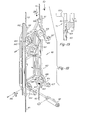
- the lifter-downpull cables 45 are located within this mast 31 to connect with the slide frame 40 and are also shown at Fig. 18 connecting with the slide frame 40.
- the lifter portions of the cables are threaded over a pair of laterally spaced upper pulleys 97 (only one being shown).
- the pulleys are mounted in suitable brackets 98 suspended from top cross brace members which form the crown 99 of the mast.
- the downpull portions of the cables 45 are threaded about a pair of laterally spaced lower pulleys 100 (only one being shown).
- the pulleys 100 are mounted in suitable upstanding brackets 101 which are affixed to a cross bar 102 connecting with the bottoms of the rear cord members 91.
- the various details as to how the cables 45 are operated and controlled by the operator are not shown. They are actuated by a pair of cylinders and a sheave arrangement in a conventional manner.
- the crown block 44 is an L shaped member which includes a vertical tubular sleeve 103 and a horizontal, narrow upright pulley case 104 at the top of the sleeve.
- the vertical sleeve 103 overhangs the forward face of the mast and is secured thereto, adjacent to the crown of the mast 31, by a pair of pivot collars 105 secured to transverse plates 106 attached to the forward face of the mast.
- the pulley case 104 extending from the top of the sleeve, will normally extend rearwardly over the mast crown 99 to cantilever a short distance therebeyond.
- the crown block 44 may thus swing from its normal rearward alignment, about the sleeve axis, and to a position at the side of the mast.
- a cable 107 extends upwardly from the hoist 46 at the forward face of the mast and into the sleeve 103.
- the cable turns thence about a first pulley 108 within the case 104 to extend horizontally to a second pulley 109 at the rearward end of the case, to turn about this pulley 109 and extend downwardly at the rear of the mast.
- the end of the cable carries a weighted head 110 and various tools such as a pipe attachment collar may also be fastened to the end of this cable.
- the pulley case 104 is supported upon a radially curved track 111 mounted upon the mast crown 99.
- a track engaging roller ll2 is mounted in suitable brackets l13 at each side of the pulley case.
- the track is suitably extended about the side of the mast 31 opposite to the operators console C to permit the boom to swing fully 90 degrees from the normal rearward position to permit the cable to be directly over pipes and other items normally carried at that side of the mast.
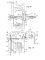
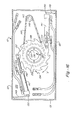
- the ground shoe 47 having a breakout means within it is formed as a flat, comparatively shallow rectangular housing having an upper plate 120, sidewalls 121 depending therefrom and a bottom cover plate 122 which is bolted to the lower edges of the sidewalls. Downwardly depending flanged feet members 123 and 124 are attached to the undersurface edges of the bottom cover plate (only two feet members being shown).
- This ground shoe is connected to the lower end of the mast 31 to outstand rearwardly therefrom by a spaced pair of upwardly inclined strut frames 125 affixed to the upper plate 120 for attachment to the lower ends of the rear upright mast cords 91.
- Each strut frame 125 has opposing upright, connective shoe plates 126 which embrace its respective mast cord 91 and is secured thereto by pins 127 (Fig. 13) fitting into holes 128 in the shoe plates and registering holes 128a in the mast cord members.
- a drill stem 53 projected from a drill 52 carried on the mast will extend through the pipe passageway 48 at the center of the ground shoe 47.
- the upper plate 120 and the bottom plate 122 are provided with aligned central openings 130 and 131 respectively.
- An upper protective cover ring 132 is mounted in the upper plate opening 130 and a lower wear ring bearing 133 is mounted in the lower plate opening 131.
- a breakout drive wheel 134 includes a central tubular shaft 135 mounted in and between the ring bearings 132 and 133.
- a bushing 136 is fitted within the tubular shaft 135 to guide a drill pipe.
- a pair of toothed, one way ratchet wheels 137 having a sprocket 138 between them are fitted about the shaft 135.
- a thrust collar 139 about the shaft 135 at the underside of the lower ratchet wheel engages a thrust bearing 140 at the lower ring bearing 133.
- the top portion of the uppermost pipe section of the string within the hole will extend through the passageway 48 of the shoe 47.
- the uppermost pipe section is then lifted out of the hole, to be gripped by tongs and the next pipe section will be held by a C-collar K by embracing flats near the top end of the pipe.
- the C-collar K is held by the shaft 135 of the breakout drive wheel 134.
- the shaft 135 is capped by a circular array of castellation slots 135 and the C-collar K includes lugs 135b depending from the collar to fit into the castellations, all as best shown at Fig. 17a.
- a pair of hydraulic cylinders 141 are mounted within the shoe cavity on trunion pivots 142 outstanding from opposite sides of the head of each cylinder to be fitted into bearing sockets 143 in the upper plate 120 and the bottom plate 122.
- the end of the reciprocal piston rod 144 of each cylinder 141 is drivably engageable with a ratchet wheel 137 to produce high torque rotation of the wheel.
- the two cylinders 141 are spaced at opposite sides of the drive wheel 134 to have their pistons 144 engageable with the ratchet wheels to rotate the drive wheel 134 in the direction of the indicated arrow 'a' at Fig. 16.
- the pipe may then be rapidly rotated to disconnect it from the pipe above by a hydraulic motor 145 mounted in the ground shoe 47, having its drive shaft carrying a sprocket 146 which is connected to the sprocket 138 between the ratchets by a chain 147.
- a bracket 148 holds the motor 145 and its sprocket 146 in place.
- the two cylinders 141 carried on pivots 142, are positioned to maintain a generally tangential driving engagement with the ratchet wheels 137 during extension of their pistons 144. In retraction they will swing past the teeth of the ratchet wheel 137.
- a tension spring 149 at each cylinder is connected between a sidewall portion 121 of the shoe 47 and a bracket 150 at the back end of the cylinder to bias the cylinder to a position of driving engagement with its ratchet wheel 137.
- a latching device 151 is associated with each piston 144 to hold the cylinder rod end away from the sprocket when it is rotating.
- a latch 152 having an inclined face is slidably mounted in an opening l53 in an end block assembly 154.
- the blade assembly is suitably mounted in the shoe housing.
- the latch is biased by a spring 155 to a rod engaging position when the piston rod 144 is fully extended.
- This piston rod 144 terminates as a head l56 which includes a grip pin 156a extending from opposite sides of the head.
- the head lies between the sprocket members 137 and pin 156a grips the valleys of the sprocket teeth.
- the slide frame 40 is formed as a rectangular, upright trough-shaped framework 160 having an open face at its rearward side.
- An upright slide channel 161 is affixed to each side of this framework.
- the slide frame is mounted in the slot cavity 93 of the mast 31 with the slide channels 161 lying against and embracing the upright rear cords 91 of the mast and thus, these rear cords 91 define a slide means whereon the slide frame is mounted.
- the rearward open face of the framework provides a pocket 162 whereinto the drill carrier 41 may swing as heretofore described (see Fig. 5).
- Upper arm braces l63 and lower arm braces 164 outstand rearwardly from each side at the top and bottom of this framework 160.
- a pivot support bracket 165 is mounted upon each arm 163 and 164 adjacent to the slide channel 161 and each bracket pivotally connects with a link 42 which also extends rearwardly from the bracket to connect with the drill carrier 41 as heretofore described.
- the pivotal connection is with a pin 166.
- a pad 167 is located at the extended end of each arm brace l63 and 164 to engage the link 42 in the bracket 165 mounted on the arm brace whenever the link is extended rearwardly horizontally.
- a cable socket l68 is located near the top and near the bottom of each slide channel 161 and the lifter-pulldown cables 45 extended into their respective sockets to connect with the slide frame.
- a pivot bracket 169 is associated with each upper arm brace 163 for connection by a pin 170 with the cylinder 43 which swings the drill carrier 41 from a rearwardly extended position to a retracted position in the pocket 162.
- the Drill Carrier 41 The Drill Carrier 41
- the carrier 41 is a versatile unit capable of holding a pile driver 50, a rotary drill 52, a diamond drill 55 and a jackhammer 57 as heretofore described.
- the pile driver installation will be described first since the pile driver 50 will ordinarily remain on the carrier when other components are used as indicated at Figs. 2 to 6.
- a conventional diesel pile driver such as manufactured by the FMC Corporation and described in its Operators Manual 1174, is preferred.
- This is an elongated, generally rectangular unit having suitable mounting holes 175 at both sides.
- a specially arranged drive anvil 176 and a drive spout 177 are mounted at the bottom of the hammer for connection with a pile or a thick-walled pipe 52 as further described.
- the carrier 41 comprises a pair of laterally-spaced, elongated side plate members 178R and 178L which are affixed to the sides of the pile driver in spaced parallelism by suitable bolts fitting into holes 175a which register with holes l75 in the pile driver and which are also held apart, and in spaced parallelism by a stiffener tube 179.
- the outer face of each plate 178 includes a pivot support bracket 181 at an upper position and at a lower position to receive the outward ends of the upper and lower links 42, extending from the slide frame 40, and the links 42 pivotally connect with the brackets 181 by pins 182.
- a post 183 out- stands from the rearward edge of each plate 178 near the lower bracket 181 to connect with the hydraulic cylinder 43.
- the linkage-cylinder mechanisms swing the carrier 41 into the pocket 162 of the slide frame 40 as heretofore described.
- the lower portions of the side plate members 178 project below the pile driver and mounting holes 184 are provided to register with mounting holes 184a in flanges of the drive anvil as hereinafter described.
- a flat, reinforced tongue 185 depends from the lower edge of each side plate 178 and the tongues fit into spaced sleeves 186 on the drive spout and other components as hereinafter described.
- a spaced, hooked catch plate 187 at the outward side of each sleeve 186 holds the drive spout, or other components, in place.
- a supplemental drive system is provided at the forward edge of the side plate 178R.
- the hydraulic motor 54 is mounted at the top of the pile driver on a drive shaft housing, plate 188, on a support plate 189 and a drive shaft 190 depends therefrom, through bearings 191 secured to the forward edge of side plate 178R to the bottom of the side plate.
- the shaft connects with rotary drilling heads 52 and 55, hereinafter further described.
- the drive anvil 176 is carried within a cylindrical housing 192 having an inset shoulder 193 at its base, lateral plate-like arms 194 holding diametrically opposing mounting plates 195 wherein mounting holes 184a are located to secure the anvil to the side plates 178R and 178L as heretofore described.
- a spout head 196 is mounted having a lower cylindrical stem projecting downwardly through the shoulder 193 and an upwardly projecting head terminating as a cap 197 wherein plastic and metallic discs 198 and 199 are placed.
- the discs are topped by a cap 200 which engages the pile driver hammer.
- the spout 177 is a solid cylindrical member having a spherical convex top surface 201 mating with a spherical concave surface 201a at the underside of the head 196.
- the spout has lateral plate-like arms 202 holding the diametrically opposing sleeves 186 which receive the tongues 185 of the side plate members 178R and 178L.
- the socket 103 of the spout receives the pipe 52 with an end shoulder 204 to abut against the end of the pipe 52 as it is being driven into the earth.
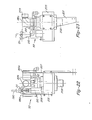
- the rotary drill head 52 may be installed on the tongues 185 by'removing the pile driver spout 177. Once installed, the drill head 52 is connected with the drive shaft 190.
- the drill head is built about a gear box 205 with mounting side plates 206 and 207 connected to the box to form sleeves 186a to receive the tongues 185 of the carrier side plates 178R and 178L so that the drill head is carried by these plates.
- the output shaft 208 which connects to the drill stem 53, extends through the gear box and the passageway through this shaft connects with an elbow 209 at the top of the gear box for fluid flow therethrough.
- the input to the gear box 205 is through an upward extension 210 with a universal coupling 211 at the top of the extension connecting with the drive shaft 190.
- a lug 212 on the gear box 205 is positioned adjacent to the elbow 209 for connection with the lift cable 107.
- the gear train within the gear box 205 is selected to provide a slower high torque rotation of the output shaft 208, responsive to high speed rotation of the drive shaft 190.
- the gears include an input pinion 213 connecting with the shaft of extension 210 which connects with drive 190.
- An intermediate gear 214 is mounted on a pinion shaft 215.
- the pinion of shaft 215 engages an output gear 216 which is keyed to the output shaft 208.
- This output shaft is comparable in diameter to the drill pipe 53 and the opening at the base is internally threaded with a tapered thread for the pipe connection. Suitable seals, keys and bearings hold the various pinions and gears in place, all of which are conventional and need not be further described.
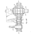
- Fig. 25 shows the drill head 52 adapted for a double wall drill stem 53 where fluid, air or water will move downwardly through the space between the two pipe walls and return through the center pipe.
- the drill head 52 carries an adaptor 247 at the base of the output shaft 208 which includes a stub shaft 248 which threads into the output shaft 208 to rotate therewith.
- a central passageway through the stub shaft extends through a reduced diameter .stem 249 at the bottom of the stub and a sized stem 250 at the bottom which fits the central passageway of the drill pipe forcing fluid flow therein and through the elbow 209.
- a pipe thread 251 above connects with the drill stem and a gland 252 wherein the stub rotates is located above the thread 251, in suitable flanges with proper fluid seals.
- An air or water supply line 253 to the gland forces the fluid through a passageway about the stem portion and into the outward space between the inner and outer pipe walls. The return flow is through the inner pipe and through the central passageway of the adaptor.
- the diamond drill head 55 shown by these figures may be installed on the tongues 185 by removing the pile driver spout 177. Once installed, the drill head 55 is connected with the drive shaft 190.
- the drill head is built about a gear box housing 220 which is embraced by a box-like case 221 having side plates 222 and a lid plate 223 at the case. Arm portions of this case 221 extend in diametric opposition from a centered output shaft 224 in the case and to sleeves 186b to receive the tongues 185 of the carrier side plates 178R and 178L so that the diamond drill is carried by the tongues.
- the output shaft 224 extends through the gear box and has a passageway 225 through it which is threaded at the bottom to connect with a drill rod 56 depending therefrom.
- the passageway 225 through this shaft connects with a fluid supply line 226 at the top of the gear box which includes a suitable elbow 227 and swivel connection 228 to facilitate good connection with a conventional fluid supply piping as the drill moves up and down the mast during operation.
- the input to the gear box is at a spline shaft 229 connected to a universal coupling 230 and thence to the drive shaft 190.
- a post 231 upstands from the lid plate 223 with a clevis at the top for connection with the lift cable 107 to facilitate mounting the unit onto the carrier.
- the gear train within the gear box is selected to provide a comparatively high speed output for the shaft 224 which is only slightly less than the high speed rotation of the drive shaft 190.
- the gears include an input gear 232 keyed to the input spline shaft 228 which engages an idler gear 233, bearing mounted on a fixed shaft 234.
- the idler gear is engaged by a drive gear 235 keyed to the output shaft 224.
- Suitable seals, keys and bearings hold the gears in place, all of which are conventional and need not be further described.
- the jackhammer 57 is mounted upon a transverse bracket 180 which is spaced between the rearward edges 178R and 178L in such a manner as to align the drill steel 58 connected to the jackhammer with a hole drilled by a rotary drill or diamond drill whenever the carrier 41 is shifted into the slide frame pocket 162 and against the mast as best illustrated at Fig. 5.
- Figs. 1 and 2 show a puller ground shoe 47a which is used with the pile driver to pull a pile out of the ground.
- This puller ground shoe 47a has the same mounting arrangement as the breakout ground shoe 47.
- Brackets 126a connect with the base of the mast to carry a U-shaped wall 160 which in turn carries a flat shoe plate 120a.
- the plate 120 bears against the ground and a pile extends through a passageway 48a when the apparatus is in use.
- a pile is lifted by increments with a pair of cylinders 161 upstanding from the shoe plate 120a at opposite sides of the passageway 48a.
- Balanced hanger straps 162 from each side of each cylinder being connected with horizontal sill bars 163.
- the pile is connected to the sill bars in any suitable manner and extension of the cylinders will lift the pile an increment. It may then be held in the passageway 48a by slips to permit the cylinders to be lowered to get another grip on the pile for raising it another increment.
Landscapes
- Engineering & Computer Science (AREA)
- Life Sciences & Earth Sciences (AREA)
- Geology (AREA)
- Mining & Mineral Resources (AREA)
- Physics & Mathematics (AREA)
- Environmental & Geological Engineering (AREA)
- Fluid Mechanics (AREA)
- General Life Sciences & Earth Sciences (AREA)
- Geochemistry & Mineralogy (AREA)
- Mechanical Engineering (AREA)
- Earth Drilling (AREA)
Applications Claiming Priority (2)
| Application Number | Priority Date | Filing Date | Title |
|---|---|---|---|
| US942550 | 1978-09-15 | ||
| US05/942,550 US4371041A (en) | 1978-09-15 | 1978-09-15 | Multi-purpose mobile drill rig |
Publications (2)
| Publication Number | Publication Date |
|---|---|
| EP0009639A2 true EP0009639A2 (fr) | 1980-04-16 |
| EP0009639A3 EP0009639A3 (fr) | 1980-08-20 |
Family
ID=25478257
Family Applications (1)
| Application Number | Title | Priority Date | Filing Date |
|---|---|---|---|
| EP79103264A Withdrawn EP0009639A3 (fr) | 1978-09-15 | 1979-09-04 | Structure de forage mobile polyvalente |
Country Status (5)
| Country | Link |
|---|---|
| US (1) | US4371041A (fr) |
| EP (1) | EP0009639A3 (fr) |
| AU (1) | AU5071579A (fr) |
| CA (1) | CA1117933A (fr) |
| ZA (1) | ZA794671B (fr) |
Cited By (12)
| Publication number | Priority date | Publication date | Assignee | Title |
|---|---|---|---|---|
| FR2486584A1 (fr) * | 1980-07-14 | 1982-01-15 | Varco Int | Appareil de forage de puits |
| FR2497869A1 (fr) * | 1981-01-12 | 1982-07-16 | Cogema | Machine de forage montee sur vehicule et procede de forage utilisant une telle machine |
| FR2498673A1 (fr) * | 1981-01-23 | 1982-07-30 | Varco Int | Appareil de forage d'un puits avec structure de guidage montee de facon mobile pour l'unite de forage |
| FR2586748A1 (fr) * | 1984-10-03 | 1987-03-06 | Triten Corp | Appareil destine au forage, a entrainement en tete |
| AU585286B2 (en) * | 1984-12-01 | 1989-06-15 | Ingersoll-Rand Company | Casing handling arrangement for a drilling rig with hydraulic top head drive |
| EP0485189A3 (en) * | 1990-11-06 | 1992-07-15 | Geo Search Co. Ltd. | Pavement structure examination vehicle |
| WO1997021902A3 (fr) * | 1995-12-12 | 1997-08-07 | Boart Longyear Company | Installation de forage |
| AU708156B2 (en) * | 1997-04-11 | 1999-07-29 | Northam Platinum Limited | Underground mining drill rig |
| WO2015163809A1 (fr) * | 2014-04-24 | 2015-10-29 | Atlas Copco Rock Drills Ab | Installation de forage et tête de forage d'une installation de forage |
| CN106715820A (zh) * | 2014-09-25 | 2017-05-24 | 安德鲁·尼姆克瑞克 | 移动式钻机 |
| NO342128B1 (no) * | 2013-12-03 | 2018-03-26 | Stimline As | Rørhåndteringsapparat |
| CN115045609A (zh) * | 2022-03-24 | 2022-09-13 | 国网浙江省电力有限公司湖州供电公司 | 一种拆分式微型桩基础专用钻机 |
Families Citing this family (105)
| Publication number | Priority date | Publication date | Assignee | Title |
|---|---|---|---|---|
| US4458768A (en) * | 1981-01-23 | 1984-07-10 | Varco International, Inc. | Top drive well drilling apparatus |
| USD282368S (en) | 1983-06-06 | 1986-01-28 | Smith Albert W | Combined erectable hydraulic drilling rig and transport trailer |
| US4539893A (en) * | 1984-05-23 | 1985-09-10 | Ingersoll-Rand Company | Power feed system for a rotary drill |
| US4697648A (en) * | 1985-09-24 | 1987-10-06 | Brandt Bernd A | Spring-loaded suspension system for augers and screw anchors |
| US4671365A (en) * | 1985-11-01 | 1987-06-09 | Ingersoll-Rand Company | Drill feeding and hoisting system for an earthdrill |
| US5107940A (en) * | 1990-12-14 | 1992-04-28 | Hydratech | Top drive torque restraint system |
| AU629137B2 (en) * | 1991-01-24 | 1992-09-24 | Frankipile Australia Pty. Limited | Foundation installation means |
| US5199507A (en) * | 1992-02-05 | 1993-04-06 | Westmoreland Harry L | Portable drilling system |
| US5236054A (en) * | 1992-09-21 | 1993-08-17 | Jack Alexander D | Combination carrier truck and umbilical drilling rig |
| DE4312368C5 (de) * | 1993-04-16 | 2008-09-25 | Abi Anlagentechnik-Baumaschinen-Industriebedarf Maschinenfabrik Und Vertriebsgesellschaft Mbh | Einrichtung zur Befestigung von Arbeitsgeräten am Hubschlitten des Mäklers von Baumaschinen |
| US5709277A (en) * | 1995-07-07 | 1998-01-20 | Geldner; Robert L. | Directional boring machine |
| DE19609899A1 (de) * | 1996-03-13 | 1997-09-18 | Wirth Co Kg Masch Bohr | Vorrichtung zur Herstellung eines Erdlochs |
| US5803189A (en) * | 1996-08-21 | 1998-09-08 | Geldner; Robert L. | Directional boring machine |
| US6061933A (en) * | 1997-04-29 | 2000-05-16 | Rogge; Steven Dean | Compactor for use with backhoe method and apparatus |
| US6481510B1 (en) * | 2000-05-26 | 2002-11-19 | 360Fiber Ltd, | Directional drill for railway drilling and method of using same |
| DE10048257A1 (de) † | 2000-09-29 | 2002-04-11 | Anlagentech Baumasch Ind | Mäkler mit Wechselvorrichtung für hydraulische Arbeitsgeräte |
| US6510908B2 (en) * | 2001-01-18 | 2003-01-28 | Hernischfeger Technologies, Inc. | Blasthole drill with rotary head carriage resiliently held on a mast |
| US6533045B1 (en) * | 2001-05-02 | 2003-03-18 | Jack M. Cooper | Portable drilling rig |
| US20030111232A1 (en) * | 2001-12-17 | 2003-06-19 | Welsh Walter Thomas | Crown block shifting apparatus and method |
| US6981855B2 (en) * | 2002-09-30 | 2006-01-03 | Sandvik Ab | Drilling rig having a compact compressor/pump assembly |
| USD477332S1 (en) | 2002-09-30 | 2003-07-15 | Schramm, Inc. | Earth drill |
| US6860337B1 (en) * | 2003-01-24 | 2005-03-01 | Helmerich & Payne, Inc. | Integrated mast and top drive for drilling rig |
| US7765749B2 (en) * | 2003-04-25 | 2010-08-03 | National Oilwell, L.P. | Fast moving drilling rig |
| US7063172B1 (en) * | 2003-12-24 | 2006-06-20 | Mark C Marentette | Grounding rod driving device |
| US6994171B2 (en) * | 2004-01-28 | 2006-02-07 | Helmerich & Payne, Inc. | Two section mast with self-aligning connections |
| AU2005244146B2 (en) * | 2004-04-30 | 2010-02-18 | Astec Industries, Inc. | Apparatus and method for modified horizontal directional drilling assembly |
| US20050241857A1 (en) * | 2004-05-03 | 2005-11-03 | Beato Christopher L | Method to transport and operate a small footprint tower to reduce environmental impact |
| US7255180B2 (en) * | 2004-05-03 | 2007-08-14 | Drillmar, Inc. | Modular drill system requiring limited field assembly and limited equipment support |
| EP1655415A1 (fr) * | 2004-11-08 | 2006-05-10 | BAUER Maschinen GmbH | Machine de travaux de construction avec mât et poulie réglable |
| ATE356918T1 (de) * | 2004-11-08 | 2007-04-15 | Bauer Maschinen Gmbh | Bauarbeitsgerät |
| EP1655450B1 (fr) * | 2004-11-08 | 2007-02-14 | BAUER Maschinen GmbH | Appareil de forage |
| US20080000662A1 (en) * | 2006-06-30 | 2008-01-03 | Tyer Robert C | Chain driven reciprocating hammer with automatic work piece input centering and clamping |
| ES2329318B1 (es) * | 2006-07-10 | 2011-02-10 | Los Bolillas, S.L. | Perforadora autotransportada multiposicionable de perforacion versatil. |
| US20080129029A1 (en) * | 2006-12-05 | 2008-06-05 | Holte Ardis L | Extensible equipment mast |
| AU2007209822A1 (en) * | 2007-03-01 | 2008-09-18 | Fairbrother Industries Limited | Post drivers |
| US7640998B2 (en) * | 2007-03-06 | 2010-01-05 | Howell Jr Richard L | Excavation apparatus |
| US20110083840A1 (en) * | 2007-03-15 | 2011-04-14 | Greg Wiedmer | Workover rig with reinforced mast |
| US7775298B2 (en) * | 2007-10-29 | 2010-08-17 | Abergeldie Holdings Pty Ltd/Abergeldie Plant Pty Ltd | Drilling assemblies and methods of drilling |
| US8549815B2 (en) * | 2008-02-29 | 2013-10-08 | National Oilwell Varco L.P. | Drilling rig masts and methods of assembly and erecting masts |
| US8813436B2 (en) | 2008-02-29 | 2014-08-26 | National Oilwell Varco, L.P. | Pinned structural connection using a pin and plug arrangement |
| US8468753B2 (en) * | 2008-02-29 | 2013-06-25 | National Oilwell Varco L.P. | Drilling rigs and erection methods |
| US7770668B2 (en) * | 2008-09-26 | 2010-08-10 | Longyear Tm, Inc. | Modular rotary drill head |
| US8875911B2 (en) * | 2009-05-13 | 2014-11-04 | National Oilwell Varco, L.P. | Drilling rig mast lift systems and methods |
| US8646549B2 (en) * | 2009-10-08 | 2014-02-11 | Atlas Copco Drilling Solutions Llc | Drilling machine power pack which includes a clutch |
| US8556003B2 (en) * | 2009-11-18 | 2013-10-15 | National Oilwell Varco, L.P. | Split sub-basement drill rig |
| EP2378001B1 (fr) * | 2010-04-16 | 2013-06-12 | BAUER Maschinen GmbH | Dispositif de traitement de sol |
| PH12013501642A1 (en) | 2011-02-07 | 2019-06-03 | Strange Invest Wa Pty Ltd | Drill rig and associated drill rig traverse system |
| US8573334B2 (en) | 2011-12-16 | 2013-11-05 | Entro Industries, Inc. | Rotation device for load transporting apparatus |
| US10556631B2 (en) | 2011-12-16 | 2020-02-11 | Entro Industries, Inc. | Low profile roller assembly |
| US9533723B2 (en) | 2011-12-16 | 2017-01-03 | Entro Industries, Inc. | Mounting structure with storable transport system |
| US9091125B2 (en) | 2012-01-16 | 2015-07-28 | National Oilwell Varco, L.P. | Collapsible substructure for a mobile drilling rig |
| US20130341059A1 (en) * | 2012-06-21 | 2013-12-26 | Complete Production Services, Inc. | Top drive sheave method and apparatus |
| US9562406B2 (en) | 2012-11-19 | 2017-02-07 | Key Energy Services, Llc | Mechanized and automated well service rig |
| US9394664B2 (en) * | 2013-03-12 | 2016-07-19 | Brooke Erin Desantis | Hydraulic breaker hammer casing assembly for pile driving |
| US9566702B2 (en) * | 2013-06-18 | 2017-02-14 | JW Tooling, LLC | Hydraulic rotator converter for a hydraulic impact hammer and method |
| JP6242629B2 (ja) * | 2013-08-21 | 2017-12-06 | 株式会社角藤 | 掘削機の作業軸連結機構 |
| USD725156S1 (en) * | 2014-04-11 | 2015-03-24 | Sandvik Mining And Construction Oy | Boring machine |
| USD733192S1 (en) * | 2014-04-11 | 2015-06-30 | Sandvik Mining And Construction Oy | Boring machine |
| USD726780S1 (en) * | 2014-04-11 | 2015-04-14 | Sandvik Mining And Construction Oy | Boring machine |
| WO2016049422A1 (fr) * | 2014-09-25 | 2016-03-31 | Andrew Niemczyk | Installation de forage mobile |
| EP3081421B1 (fr) * | 2015-04-17 | 2019-07-31 | Vermeer Manufacturing Company | Système de refroidissement de moteur comportant un ventilateur à basse vitesse |
| CN105002908B (zh) * | 2015-07-31 | 2016-09-28 | 周兆弟 | 综合打桩机 |
| US9784040B2 (en) | 2015-09-17 | 2017-10-10 | Entro Industries, Inc. | Oil rig pony substructures with outrigger sections |
| USD780812S1 (en) * | 2015-10-15 | 2017-03-07 | Andrew Niemczyk | Compact mobile drilling rig |
| US10738545B2 (en) | 2015-12-15 | 2020-08-11 | Prostar Energy Technologies (Usa) Llc | Pipe handler and pipe loader for a well rig |
| CN105386723A (zh) * | 2015-12-18 | 2016-03-09 | 黄朝阳 | 长螺旋桅杆可旋转式钻机 |
| USD866613S1 (en) * | 2016-04-11 | 2019-11-12 | Roddie, Inc. | Hand portable directional drill |
| JP6692579B2 (ja) * | 2016-08-03 | 2020-05-13 | 日本車輌製造株式会社 | 杭打機 |
| AU201710287S (en) * | 2017-01-18 | 2017-02-08 | Deep Exploration Tech Crc Limited | Mobile Coiled Tubing Drilling Apparatus |
| RU2641677C1 (ru) * | 2017-03-10 | 2018-01-19 | Публичное акционерное общество "Татнефть" имени В.Д. Шашина | Установка для проведения спуско-подъемных операций в скважинах с наклонным устьем |
| US10899401B2 (en) | 2017-06-05 | 2021-01-26 | Entro Industries, Inc. | Yaw alignment system |
| US10793409B2 (en) | 2017-07-12 | 2020-10-06 | Entro Industries, Inc. | Lifting loads with lifting devices |
| US10889961B2 (en) | 2017-08-08 | 2021-01-12 | Entro Industries, Inc. | Automatic walking for a load transporting apparatus |
| US10895882B2 (en) | 2017-08-01 | 2021-01-19 | Entro Industries, Inc. | Controlling load transporting devices |
| USD971969S1 (en) * | 2017-08-04 | 2022-12-06 | Liberty Oilfield Services Llc | Oilfield frac pump |
| US11180319B2 (en) | 2017-11-22 | 2021-11-23 | Entro Industries, Inc. | Skid system for load transport apparatus |
| IT201800001088A1 (it) * | 2018-01-16 | 2019-07-16 | Soilmec Spa | Assieme per la movimentazione di una attrezzatura di scavo o perforazione del terreno e metodo di attuazione. |
| USD851688S1 (en) * | 2018-01-17 | 2019-06-18 | The Charles Machine Works, Inc. | Horizontal directional drill |
| USD851132S1 (en) * | 2018-01-17 | 2019-06-11 | The Charles Machine Works, Inc. | Horizontal directional drill |
| US11407460B2 (en) | 2018-05-31 | 2022-08-09 | Entro Industries, Inc. | Nonlinear walking apparatus |
| US11015635B2 (en) * | 2018-07-24 | 2021-05-25 | Ojjo, Inc. | Threaded truss foundations and related systems, methods, and machines |
| US11319808B2 (en) * | 2018-10-12 | 2022-05-03 | Caterpillar Global Mining Equipment Llc | Hose retention system for drilling machine |
| US11492774B2 (en) | 2019-01-04 | 2022-11-08 | Ojjo, Inc. | Systems, methods and machines for driving screw anchors |
| USD927558S1 (en) * | 2019-03-05 | 2021-08-10 | Yamamoto Foundation Works Co., Ltd. | Boring machine with casing driver |
| CN109989704B (zh) * | 2019-04-26 | 2024-04-09 | 倬方钻探工程集团有限责任公司 | 越野轻便钻机 |
| US11131111B2 (en) * | 2019-08-09 | 2021-09-28 | Caterpillar Global Mining Equipment Llc | Mast coupling assembly for a mobile drilling machine |
| US10954645B2 (en) * | 2019-08-23 | 2021-03-23 | Christopher DeBlauw | System and apparatus for driving piles |
| US11628525B2 (en) * | 2019-11-11 | 2023-04-18 | Ojjo, Inc. | Devices, machines, and systems for automated truss assembly and crimping |
| WO2021119785A1 (fr) * | 2019-12-20 | 2021-06-24 | Petróleo Brasileiro S.A. - Petrobras | Unité compacte de périphériques pour sondes de production terrestre |
| AU2021207686A1 (en) * | 2020-01-15 | 2022-09-08 | Ojjo, Inc. | Systems, methods, and machines for constructing solar foundations |
| USD1009944S1 (en) * | 2020-03-10 | 2024-01-02 | Jiangsu Xcmg Construction Machinery Research Institute Ltd. | Rotary drilling rig |
| CN112443276B (zh) * | 2020-12-01 | 2022-11-25 | 中国地质科学院 | 一种致密岩地质勘探取样钻井系统及其工作方法 |
| CN112963185B (zh) * | 2021-03-15 | 2022-12-27 | 中国煤炭科工集团太原研究院有限公司 | 滑轨装置和具有它的锚杆钻机 |
| CN112963184B (zh) * | 2021-03-15 | 2022-12-27 | 中国煤炭科工集团太原研究院有限公司 | 锚杆支护施工装置和履带式多臂帮锚杆钻车 |
| US11253883B1 (en) | 2021-06-09 | 2022-02-22 | Russell R. Gohl | Cavity cleaning and coating system |
| CN113309477B (zh) * | 2021-06-23 | 2022-06-17 | 贵州盘江煤层气开发利用有限责任公司 | 一种适用于多煤层条件的煤层气勘探开发的多功能钻机 |
| US11535321B1 (en) * | 2022-08-24 | 2022-12-27 | Russell R. Gohl | Trailer system |
| CN115788283A (zh) * | 2022-11-18 | 2023-03-14 | 中国水利水电建设工程咨询贵阳有限公司 | 一种冻土地区地质勘探的钻探设备 |
| CN116537726B (zh) * | 2023-05-19 | 2024-05-28 | 宁波市电力设计院有限公司 | 一种三维地质建模用取芯装置 |
| CN116876978B (zh) * | 2023-08-03 | 2024-06-07 | 深蓝(天津)智能制造有限责任公司 | 一种井下管柱电控钻孔工具 |
| CN117188960B (zh) * | 2023-08-29 | 2026-05-12 | 中铁十五局集团有限公司 | 适应岩质地层的同步式带加腋水平悬臂的矩形深孔钻机 |
| CN118326968B (zh) * | 2024-06-14 | 2024-08-20 | 国网安徽省电力有限公司宿州供电公司 | 一种电力工程用地锚拆除机 |
| CN119124708A (zh) * | 2024-08-01 | 2024-12-13 | 天津大学 | 一种污染场地高保真采样装置及方法 |
| CN120231479B (zh) * | 2025-05-09 | 2025-10-21 | 徐州融河机械制造有限公司 | 一种旋挖钻机 |
| CN120940366B (zh) * | 2025-09-30 | 2026-05-08 | 河北庭耀建设项目管理有限公司 | 一种打桩工程用土壤污染控制与治理设备 |
Family Cites Families (15)
| Publication number | Priority date | Publication date | Assignee | Title |
|---|---|---|---|---|
| FR350832A (fr) | 1905-01-18 | 1905-06-27 | De Fondations Par Compression Mecanique Du Sol | Sonnette métallique à usages multiples |
| US2904310A (en) * | 1957-08-19 | 1959-09-15 | Raymond F Leonard | Portable hydraulic drilling rig |
| US2963100A (en) * | 1957-10-23 | 1960-12-06 | Raymond Int Inc | Pile driving hammers |
| US3280925A (en) * | 1961-06-19 | 1966-10-25 | Becker Drilling Alberta Ltd | Method and apparatus for impact drilling of overburden |
| FR92130E (fr) * | 1966-06-30 | 1968-09-27 | Benoto Sa | Appareil permettant de transformer une foreuse, d'un type quelconque, en foreuse rotative |
| US3438450A (en) * | 1967-02-24 | 1969-04-15 | Failing Ind Inc | Hydraulically operated earth boring tools |
| US3576218A (en) * | 1969-07-28 | 1971-04-27 | Edgar J Lisenby | Combined earth boring and post driving apparatus |
| US3613906A (en) * | 1970-05-20 | 1971-10-19 | Bruce Deyo | Drill stem storage and handling mechanism |
| US3708024A (en) * | 1971-03-10 | 1973-01-02 | Sanderson Cyclone Drill Co | Drilling machine |
| AU460673B2 (en) * | 1971-04-30 | 1975-04-16 | Longyear (Australia) Pty. Ltd | Dual purpose drill rig |
| FR2138415B1 (fr) | 1971-05-25 | 1974-10-11 | Activite Atom Avance | |
| US3766995A (en) * | 1971-10-20 | 1973-10-23 | Dresser Ind | Earth boring machine with multi-motor drive |
| US3896887A (en) * | 1973-12-26 | 1975-07-29 | Gardner Denver Co | Mounting for drill rig mast |
| US3921739A (en) * | 1974-09-30 | 1975-11-25 | Farmer Foundation Company | Walking platform for drilling rigs and other heavy machinery |
| US4102094A (en) * | 1975-09-26 | 1978-07-25 | The Foundation Equipment Corporation | Bottom brace for crane |
-
1978
- 1978-09-15 US US05/942,550 patent/US4371041A/en not_active Expired - Lifetime
-
1979
- 1979-09-04 EP EP79103264A patent/EP0009639A3/fr not_active Withdrawn
- 1979-09-05 ZA ZA00794671A patent/ZA794671B/xx unknown
- 1979-09-11 AU AU50715/79A patent/AU5071579A/en not_active Abandoned
- 1979-09-14 CA CA000335696A patent/CA1117933A/fr not_active Expired
Cited By (17)
| Publication number | Priority date | Publication date | Assignee | Title |
|---|---|---|---|---|
| FR2486584A1 (fr) * | 1980-07-14 | 1982-01-15 | Varco Int | Appareil de forage de puits |
| FR2497869A1 (fr) * | 1981-01-12 | 1982-07-16 | Cogema | Machine de forage montee sur vehicule et procede de forage utilisant une telle machine |
| FR2498673A1 (fr) * | 1981-01-23 | 1982-07-30 | Varco Int | Appareil de forage d'un puits avec structure de guidage montee de facon mobile pour l'unite de forage |
| DE3201425A1 (de) * | 1981-01-23 | 1982-10-21 | Varco International Inc., 92668 Orange, Calif. | Tiefbohrvorrichtung und dafuer vorgesehene bohreinheit |
| FR2586748A1 (fr) * | 1984-10-03 | 1987-03-06 | Triten Corp | Appareil destine au forage, a entrainement en tete |
| AU585286B2 (en) * | 1984-12-01 | 1989-06-15 | Ingersoll-Rand Company | Casing handling arrangement for a drilling rig with hydraulic top head drive |
| EP0485189A3 (en) * | 1990-11-06 | 1992-07-15 | Geo Search Co. Ltd. | Pavement structure examination vehicle |
| US5794723A (en) * | 1995-12-12 | 1998-08-18 | Boart Longyear Company | Drilling rig |
| WO1997021902A3 (fr) * | 1995-12-12 | 1997-08-07 | Boart Longyear Company | Installation de forage |
| AU708156B2 (en) * | 1997-04-11 | 1999-07-29 | Northam Platinum Limited | Underground mining drill rig |
| NO342128B1 (no) * | 2013-12-03 | 2018-03-26 | Stimline As | Rørhåndteringsapparat |
| WO2015163809A1 (fr) * | 2014-04-24 | 2015-10-29 | Atlas Copco Rock Drills Ab | Installation de forage et tête de forage d'une installation de forage |
| CN106232931A (zh) * | 2014-04-24 | 2016-12-14 | 阿特拉斯·科普柯凿岩设备有限公司 | 钻机和钻机的钻头 |
| CN106232931B (zh) * | 2014-04-24 | 2018-09-25 | 安百拓凿岩有限公司 | 钻机和钻机的钻头 |
| US10174555B2 (en) | 2014-04-24 | 2019-01-08 | Epiroc Rock Drills Aktiebolag | Drilling rig and drill head of a drilling rig |
| CN106715820A (zh) * | 2014-09-25 | 2017-05-24 | 安德鲁·尼姆克瑞克 | 移动式钻机 |
| CN115045609A (zh) * | 2022-03-24 | 2022-09-13 | 国网浙江省电力有限公司湖州供电公司 | 一种拆分式微型桩基础专用钻机 |
Also Published As
| Publication number | Publication date |
|---|---|
| US4371041A (en) | 1983-02-01 |
| ZA794671B (en) | 1980-08-27 |
| AU5071579A (en) | 1980-03-20 |
| EP0009639A3 (fr) | 1980-08-20 |
| CA1117933A (fr) | 1982-02-09 |
Similar Documents
| Publication | Publication Date | Title |
|---|---|---|
| US4371041A (en) | Multi-purpose mobile drill rig | |
| US5213169A (en) | Exploration-sampling drilling system | |
| US2849212A (en) | Drilling apparatus | |
| US3645343A (en) | Rotary drilling machine | |
| US7469754B2 (en) | Apparatus for slant drilling | |
| US6315059B1 (en) | Portable water well drill | |
| US4290495A (en) | Portable workover rig with extendable mast substructure, platform mounted drawworks and adjustable wellhead anchor | |
| AU593643B2 (en) | Drilling apparatus | |
| US4077671A (en) | Subterranean drilling and slurry mining method | |
| EP0245394A1 (fr) | Procede et installation de forage pour le forage d'un puits. | |
| US3920087A (en) | Rotary drive and joint breakout mechanism | |
| US5186266A (en) | Multi-walled drill string for exploration-sampling drilling systems | |
| US3009521A (en) | Drive for earth boring tools | |
| CN118008130A (zh) | 一种钻深1000米的履带移动式柴油钻机 | |
| EP4248051B1 (fr) | Système de manipulation de tige pour appareil de forage | |
| US2803434A (en) | Rotary well drilling machine | |
| JPS61176788A (ja) | きりもみおよび/またはつり上げ機械 | |
| US2746720A (en) | Posthole digger | |
| US3746110A (en) | Auger section positioning hoist having pendent control means | |
| US4582146A (en) | Earth drilling apparatus | |
| CA2564357C (fr) | Appareil et methode pour l'installation de forage directionnel horizontal modifiee | |
| US4223870A (en) | Bailer for top head drive rotary well drills | |
| CA2503057C (fr) | Vehicule de servitude multifonction pour entretien des puits | |
| GB1603608A (en) | Drive unit for drill rig | |
| US2976942A (en) | Apparatus for drilling horizontally extending holes in embankments and walls |
Legal Events
| Date | Code | Title | Description |
|---|---|---|---|
| PUAI | Public reference made under article 153(3) epc to a published international application that has entered the european phase |
Free format text: ORIGINAL CODE: 0009012 |
|
| AK | Designated contracting states |
Designated state(s): BE DE FR GB IT NL SE |
|
| PUAL | Search report despatched |
Free format text: ORIGINAL CODE: 0009013 |
|
| AK | Designated contracting states |
Designated state(s): BE DE FR GB IT NL SE |
|
| STAA | Information on the status of an ep patent application or granted ep patent |
Free format text: STATUS: THE APPLICATION IS DEEMED TO BE WITHDRAWN |
|
| 18D | Application deemed to be withdrawn |
Effective date: 19810605 |
|
| RIN1 | Information on inventor provided before grant (corrected) |
Inventor name: REGIMBAL, RICHARD R. Inventor name: BECKER, FLOYD W. |