EP0009900B1 - Filtre monolithique à bande passante symétrique par rapport à la fréquence centrale - Google Patents
Filtre monolithique à bande passante symétrique par rapport à la fréquence centrale Download PDFInfo
- Publication number
- EP0009900B1 EP0009900B1 EP79301868A EP79301868A EP0009900B1 EP 0009900 B1 EP0009900 B1 EP 0009900B1 EP 79301868 A EP79301868 A EP 79301868A EP 79301868 A EP79301868 A EP 79301868A EP 0009900 B1 EP0009900 B1 EP 0009900B1
- Authority
- EP
- European Patent Office
- Prior art keywords
- filter
- monolithic crystal
- passband
- series
- electrodes
- Prior art date
- Legal status (The legal status is an assumption and is not a legal conclusion. Google has not performed a legal analysis and makes no representation as to the accuracy of the status listed.)
- Expired
Links
- 239000013078 crystal Substances 0.000 title claims description 55
- 239000003990 capacitor Substances 0.000 claims description 14
- 230000009466 transformation Effects 0.000 claims description 3
- 238000000844 transformation Methods 0.000 claims description 3
- 238000010586 diagram Methods 0.000 description 7
- 230000003068 static effect Effects 0.000 description 3
- 230000015556 catabolic process Effects 0.000 description 1
- 230000008878 coupling Effects 0.000 description 1
- 238000010168 coupling process Methods 0.000 description 1
- 238000005859 coupling reaction Methods 0.000 description 1
- 238000006731 degradation reaction Methods 0.000 description 1
- 238000004519 manufacturing process Methods 0.000 description 1
Images
Classifications
-
- H—ELECTRICITY
- H03—ELECTRONIC CIRCUITRY
- H03H—IMPEDANCE NETWORKS, e.g. RESONANT CIRCUITS; RESONATORS
- H03H9/00—Networks comprising electromechanical or electro-acoustic elements; Electromechanical resonators
- H03H9/46—Filters
- H03H9/54—Filters comprising resonators of piezoelectric or electrostrictive material
- H03H9/542—Filters comprising resonators of piezoelectric or electrostrictive material including passive elements
Definitions
- the present invention relates to monolithic crystal filters having a predetermined passband symmetrically located about a center frequency.
- monolithic crystal filters are basically described in U.S. patent no. 3,564,463.
- the aforementioned patent further describes the use of bridging capacitors connected between the input and output electrodes of the monolithic crystal filter element for increasing the passband selectivity of a monolithic crystal filter.
- two or more monolithic crystal filter elements with bridging capacitors may be cascaded. Such an arrangement of monolithic crystal filter elements is useful in the IF line up of radio receivers.
- the resonating frequencies of the electrode pairs on the monolithic crystal filter elements are selected to be below the passband center frequency so that capacitive coupling may be utilized between successive monolithic crystal filter elements.
- the frequency response of these monolithic crystal filters is not symmetrically located with respect to the passband center frequency. This creates problems in applications, such as in highly selective radio receivers, where symmetrical selectivity is important.
- a monolithic crystal filter for passing a predetermined passband of frequencies having a predetermined passband center frequency includes a monolithic crystal filter element, a series impedance connected to the monolithic crystal filter element and a bridging impedance connected across the monolithic crystal filter element and the series impedance.
- the monolithic crystal filter element has two pairs of acoustically coupled electrodes which resonate at substantially the same frequency.
- the series, impedance is connected to one of the electrode pairs for adapting the resonating frequency of the respective electrode pair so that the geometric mean of the adapted and non-adapted electrode-pair resonating frequencies is substantially the same as the passband center frequency.
- the bridging impedance is connected between the non-adapted electrode pair of the monolithic crystal filter element and the series impedance for providing symmetrically located stopbands above and below the filter passband.
- the monolithic crystal filter provides an improved frequency response which has relatively steep and symmetrical skirts in the filter stopbands.
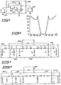
- a monolithic crystal filter 100 embodying the present invention.
- the filter includes a monolithic crystal filter element 101, a series impedance 102 and a bridging impedance 103 connected across the monolithic crystal filter element 101 and the series impedance 102.
- the monolithic crystal filter may be advantageously utilized in a narrow-band radio receiver where it is necessary to have a highly selective filter in the intermediate-frequency (IF) stages.
- IF stages of an FM receiver may be tuned to frequencies centered at 10.7 MHz.
- the IF stages of an FM receiver it is very important that the IF signal be filtered symmetrically around the IF center frequency. Significant degradation in the performance of the FM receiver will be produced if the IF passband is asymmetrical about the IF center frequency.
- the monolithic crystal filter 100 of Fig. 1 is terminated at the input by input impedance 104 and at the output by output impedance 105. As previously mentioned, the input and output of the monolithic crystal filter 100 may be connected between IF stages. Furthermore, the monolithic crystal filter 100 may be cascaded with another monolithic crystal filter 100 or another monolithic crystal filter element 101. If the monolithic crystal filter 100 is cascaded with another monolithic crystal filter element 101, the cascaded arrangement exhibits a frequency response similar to that illustrated in Fig. 2.
- the frequency response of Fig. 2 is symmetrically located about a passband center frequency F c , which here is 10.7 MHz or the IF center frequency, and has upper and lower stopbands situated approximately 20 KHz from the center frequency.
- the cascaded circuit exhibits a response which has a passband of approximately 40 KHz and a stopband attenuation of greater than 50 dB.
- the monolithic crystal element 101 may be any suitable commercially available monolithic crystal element which has two pairs of electrodes that exhibit substantially identical resonating frequencies.
- the resonating frequencies of the electrode pairs are preferably located below the passband center frequency. Alternatively, the resonating frequencies of the electrode pairs may also be located above the passband center frequency.
- the electrodes on one major surface are connected to signal ground and the electrodes on the opposite major surface are arranged such that the first of the electrodes is connected to the series impedance 102 and the second of the electrodes is connected to the bridging impedance 103.
- the series impedance 102 adapts the frequency of the electrode pair to which it is connected such that the geometric mean, i.e.
- the bridging impedance 103 is connected across the series impedance 102 and monolithic crystal filter element 101 to provide upper and lower stopbands for attenuating frequencies at the skirts of the filter device.
- Fig. 3 a detailed circuit diagram is illustrated for the generalized circuit diagram of Fig. 1, where circuitry within the dashed lines in Fig. 3 is identified by reference numerals of corresponding blocks of Fig. 1.
- the output impedance 105 may be generally represented by a capacitor C L and a resistor R L .
- the bridging impedance 103 may be a capacitor Cg.
- the monolithic crystal filter element 101 may be replaced by an equivalent circuit model, as is known in the art, where C 01 and R s1 , C m1 and L m1 are substantially identical to C 02 , R s2 , C m2 and L m2 , respectively.
- the capacitors C 01 and C 02 are termed static capacitances and are the capacitance of the electrode pairs themselves.
- the resonating frequency of the first electrode circuit formed by R s1 , C m1 , L m1 and L 12 is substantially identical to the resonating frequency of the second electrode circuit formed by R s2 , C m2' L m2 and L 12 .
- the series impedance 102 is added to move the resonating frequency for the first electrode circuit above the resonating frequency of the second electrode circuit.
- the resonating frequency of the first electrode circuit must be raised by the series impedance 102.
- the series impedance In order to raise the resonating frequency of the first electrode circuit, the series impedance must be capacitive. Therefore, capacitor C a is added.
- the static capacitance C 01 In order to realize the improvement in the selectivity characteristic of the monolithic crystal filter resulting from the series impedance 102, the static capacitance C 01 must be compensated.
- an inductor L o can be used to resonate with C 01 at the passband center frequency.
- an inductor L a is added to the input impedance 104.
- the resistance R, of the input impedance 104 is the equivalent series resistance of the preceding stage connected to the input of the monolithic crystal filter.
- the value of the terminating resistance R s is dictated by the desired filter selectivity characteristic.
- the value of the inductor L o will be relatively large compared to the values of other inductors used throughout the IF section of the receiver. Therefore, impedance transformations may be utilized to transform the inductor L o to equivalent reactive components having more suitable values.
- the electrical components of the input impedance 104 and the series impedance 102 of Fig. 3 may be transformed by impedance transformations known in the art to the arrangement of electrical components for the input impedance 104 and series impedance 102 of Fig. 4.
Landscapes
- Physics & Mathematics (AREA)
- Acoustics & Sound (AREA)
- Filters And Equalizers (AREA)
- Piezo-Electric Or Mechanical Vibrators, Or Delay Or Filter Circuits (AREA)
Claims (10)
Applications Claiming Priority (2)
| Application Number | Priority Date | Filing Date | Title |
|---|---|---|---|
| US05/950,201 US4224586A (en) | 1978-10-10 | 1978-10-10 | Monolithic crystal filter having a passband symmetrical about a center frequency |
| US950201 | 1978-10-10 |
Publications (2)
| Publication Number | Publication Date |
|---|---|
| EP0009900A1 EP0009900A1 (fr) | 1980-04-16 |
| EP0009900B1 true EP0009900B1 (fr) | 1982-12-01 |
Family
ID=25490099
Family Applications (1)
| Application Number | Title | Priority Date | Filing Date |
|---|---|---|---|
| EP79301868A Expired EP0009900B1 (fr) | 1978-10-10 | 1979-09-12 | Filtre monolithique à bande passante symétrique par rapport à la fréquence centrale |
Country Status (12)
| Country | Link |
|---|---|
| US (1) | US4224586A (fr) |
| EP (1) | EP0009900B1 (fr) |
| JP (1) | JPS5552624A (fr) |
| AR (1) | AR217203A1 (fr) |
| AU (1) | AU524799B2 (fr) |
| BR (1) | BR7906228A (fr) |
| CA (1) | CA1125397A (fr) |
| DE (1) | DE2964149D1 (fr) |
| IL (1) | IL58156A (fr) |
| MX (1) | MX148075A (fr) |
| PH (1) | PH18857A (fr) |
| ZA (1) | ZA794565B (fr) |
Families Citing this family (1)
| Publication number | Priority date | Publication date | Assignee | Title |
|---|---|---|---|---|
| DE3409927A1 (de) * | 1984-03-17 | 1985-09-26 | Ernst Leitz Wetzlar Gmbh, 6330 Wetzlar | Breitbandiges anpassungsnetzwerk |
Family Cites Families (6)
| Publication number | Priority date | Publication date | Assignee | Title |
|---|---|---|---|---|
| US2198684A (en) * | 1938-09-20 | 1940-04-30 | Bell Telephone Labor Inc | Wave filter |
| US2271870A (en) * | 1939-11-10 | 1942-02-03 | Bell Telephone Labor Inc | Wave transmission network |
| FR1523518A (fr) * | 1966-04-11 | 1968-05-03 | Western Electric Co | Dispositif acoustique servant à transmettre de l'énergie entre deux circuits d'énergie |
| US3564463A (en) * | 1966-04-11 | 1971-02-16 | Bell Telephone Labor Inc | Monolithic piezoelectric filter having mass loaded electrodes for resonation regions acoustically coupled together |
| US3716808A (en) * | 1971-05-20 | 1973-02-13 | Motorola Inc | Bandpass filter including monolithic crystal elements with resonating portions selected for symmetrical response |
| CA1101945A (fr) * | 1977-04-15 | 1981-05-26 | Henry K. Yee | Filtre de bande laterale unique a cristal monolithique |
-
1978
- 1978-10-10 US US05/950,201 patent/US4224586A/en not_active Expired - Lifetime
-
1979
- 1979-08-29 CA CA334,706A patent/CA1125397A/fr not_active Expired
- 1979-08-29 ZA ZA00794565A patent/ZA794565B/xx unknown
- 1979-08-31 IL IL58156A patent/IL58156A/xx unknown
- 1979-09-12 DE DE7979301868T patent/DE2964149D1/de not_active Expired
- 1979-09-12 EP EP79301868A patent/EP0009900B1/fr not_active Expired
- 1979-09-21 AU AU51100/79A patent/AU524799B2/en not_active Ceased
- 1979-09-28 BR BR7906228A patent/BR7906228A/pt unknown
- 1979-10-02 JP JP12725779A patent/JPS5552624A/ja active Pending
- 1979-10-04 PH PH23111A patent/PH18857A/en unknown
- 1979-10-09 AR AR278432A patent/AR217203A1/es active
- 1979-10-10 MX MX179605A patent/MX148075A/es unknown
Also Published As
| Publication number | Publication date |
|---|---|
| CA1125397A (fr) | 1982-06-08 |
| EP0009900A1 (fr) | 1980-04-16 |
| IL58156A0 (en) | 1979-12-30 |
| DE2964149D1 (en) | 1983-01-05 |
| ZA794565B (en) | 1980-08-27 |
| MX148075A (es) | 1983-03-10 |
| AU5110079A (en) | 1980-04-17 |
| US4224586A (en) | 1980-09-23 |
| AR217203A1 (es) | 1980-02-29 |
| IL58156A (en) | 1981-11-30 |
| PH18857A (en) | 1985-10-21 |
| BR7906228A (pt) | 1980-07-15 |
| AU524799B2 (en) | 1982-10-07 |
| JPS5552624A (en) | 1980-04-17 |
Similar Documents
| Publication | Publication Date | Title |
|---|---|---|
| US4785270A (en) | Monolithic lattice saw filter | |
| US5499002A (en) | Resonator filter utilizing cascaded impedance inverters | |
| US4028647A (en) | Monolithic crystal filters | |
| US5157362A (en) | Narrow band notch filter with extended passband | |
| US3609601A (en) | Monolithic filter having "m" derived characteristics | |
| US3671889A (en) | Broadband composite filter circuit | |
| US4423394A (en) | Multiple pole bandpass filter having monolithic crystal elements | |
| US4224586A (en) | Monolithic crystal filter having a passband symmetrical about a center frequency | |
| US4156214A (en) | Multipole resonator | |
| GB1022306A (en) | Improvements in or relating to bandpass filters | |
| CA1101945A (fr) | Filtre de bande laterale unique a cristal monolithique | |
| US5369382A (en) | Two-pole monolithic crystal filter including shunt resonator stages | |
| US3676806A (en) | Polylithic crystal bandpass filter having attenuation pole frequencies in the lower stopband | |
| US3716808A (en) | Bandpass filter including monolithic crystal elements with resonating portions selected for symmetrical response | |
| US3983518A (en) | Filter chain | |
| US4281300A (en) | Multi-pole crystal filter and method of improving the frequency response | |
| EP0156808B1 (fr) | Appareil pour la suppression de poles d'attenuation parasites dans des filtres piezo-electriques | |
| US4268807A (en) | Band-pass filter and gain stage | |
| US4007434A (en) | Notch filter | |
| US4205284A (en) | Electrical frequency filter comprising piezoelectric crystals | |
| JPH09116379A (ja) | 弾性表面波フィルタ | |
| US4006437A (en) | Frequency filter | |
| JPS632404A (ja) | 誘電体フイルタの帯域幅調整方法 | |
| US2216541A (en) | Wave filter | |
| JPS6177408A (ja) | 有極形ロ−パスフイルタ |
Legal Events
| Date | Code | Title | Description |
|---|---|---|---|
| PUAI | Public reference made under article 153(3) epc to a published international application that has entered the european phase |
Free format text: ORIGINAL CODE: 0009012 |
|
| AK | Designated contracting states |
Designated state(s): DE FR GB NL |
|
| 17P | Request for examination filed | ||
| GRAA | (expected) grant |
Free format text: ORIGINAL CODE: 0009210 |
|
| AK | Designated contracting states |
Designated state(s): DE FR GB NL |
|
| REF | Corresponds to: |
Ref document number: 2964149 Country of ref document: DE Date of ref document: 19830105 |
|
| ET | Fr: translation filed | ||
| PGFP | Annual fee paid to national office [announced via postgrant information from national office to epo] |
Ref country code: DE Payment date: 19840704 Year of fee payment: 6 |
|
| PGFP | Annual fee paid to national office [announced via postgrant information from national office to epo] |
Ref country code: FR Payment date: 19840709 Year of fee payment: 6 |
|
| PGFP | Annual fee paid to national office [announced via postgrant information from national office to epo] |
Ref country code: NL Payment date: 19870930 Year of fee payment: 9 |
|
| PG25 | Lapsed in a contracting state [announced via postgrant information from national office to epo] |
Ref country code: GB Effective date: 19880912 |
|
| PG25 | Lapsed in a contracting state [announced via postgrant information from national office to epo] |
Ref country code: NL Effective date: 19890401 |
|
| REG | Reference to a national code |
Ref country code: GB Ref legal event code: PCNP |
|
| NLV4 | Nl: lapsed or anulled due to non-payment of the annual fee | ||
| PG25 | Lapsed in a contracting state [announced via postgrant information from national office to epo] |
Ref country code: FR Free format text: LAPSE BECAUSE OF NON-PAYMENT OF DUE FEES Effective date: 19890531 |
|
| GBPC | Gb: european patent ceased through non-payment of renewal fee | ||
| PG25 | Lapsed in a contracting state [announced via postgrant information from national office to epo] |
Ref country code: DE Effective date: 19890601 |
|
| REG | Reference to a national code |
Ref country code: FR Ref legal event code: ST |
|
| PLBE | No opposition filed within time limit |
Free format text: ORIGINAL CODE: 0009261 |
|
| STAA | Information on the status of an ep patent application or granted ep patent |
Free format text: STATUS: NO OPPOSITION FILED WITHIN TIME LIMIT |