EP0010021B1 - Dispositif d'impression du type série-parallèle pour imprimante et télécopieur comportant un tel dispositif - Google Patents
Dispositif d'impression du type série-parallèle pour imprimante et télécopieur comportant un tel dispositif Download PDFInfo
- Publication number
- EP0010021B1 EP0010021B1 EP79400654A EP79400654A EP0010021B1 EP 0010021 B1 EP0010021 B1 EP 0010021B1 EP 79400654 A EP79400654 A EP 79400654A EP 79400654 A EP79400654 A EP 79400654A EP 0010021 B1 EP0010021 B1 EP 0010021B1
- Authority
- EP
- European Patent Office
- Prior art keywords
- electrode holder
- printing
- electrodes
- coil
- displacement
- Prior art date
- Legal status (The legal status is an assumption and is not a legal conclusion. Google has not performed a legal analysis and makes no representation as to the accuracy of the status listed.)
- Expired
Links
- 238000006073 displacement reaction Methods 0.000 claims description 9
- XEEYBQQBJWHFJM-UHFFFAOYSA-N Iron Chemical group [Fe] XEEYBQQBJWHFJM-UHFFFAOYSA-N 0.000 claims description 7
- 230000003287 optical effect Effects 0.000 claims description 7
- 230000008878 coupling Effects 0.000 claims 2
- 238000010168 coupling process Methods 0.000 claims 2
- 238000005859 coupling reaction Methods 0.000 claims 2
- 238000013519 translation Methods 0.000 description 24
- 230000014616 translation Effects 0.000 description 24
- 238000010586 diagram Methods 0.000 description 3
- 230000009471 action Effects 0.000 description 2
- 230000007423 decrease Effects 0.000 description 2
- 230000007246 mechanism Effects 0.000 description 2
- 230000003321 amplification Effects 0.000 description 1
- 230000033228 biological regulation Effects 0.000 description 1
- 239000004020 conductor Substances 0.000 description 1
- 230000005284 excitation Effects 0.000 description 1
- 230000006872 improvement Effects 0.000 description 1
- 239000012212 insulator Substances 0.000 description 1
- 238000012423 maintenance Methods 0.000 description 1
- 238000000034 method Methods 0.000 description 1
- 238000003199 nucleic acid amplification method Methods 0.000 description 1
- 230000008569 process Effects 0.000 description 1
- 230000009467 reduction Effects 0.000 description 1
- 238000005070 sampling Methods 0.000 description 1
- 230000009466 transformation Effects 0.000 description 1
- 238000000844 transformation Methods 0.000 description 1
Images

Classifications
-
- B—PERFORMING OPERATIONS; TRANSPORTING
- B41—PRINTING; LINING MACHINES; TYPEWRITERS; STAMPS
- B41J—TYPEWRITERS; SELECTIVE PRINTING MECHANISMS, i.e. MECHANISMS PRINTING OTHERWISE THAN FROM A FORME; CORRECTION OF TYPOGRAPHICAL ERRORS
- B41J25/00—Actions or mechanisms not otherwise provided for
- B41J25/001—Mechanisms for bodily moving print heads or carriages parallel to the paper surface
- B41J25/006—Mechanisms for bodily moving print heads or carriages parallel to the paper surface for oscillating, e.g. page-width print heads provided with counter-balancing means or shock absorbers
-
- B—PERFORMING OPERATIONS; TRANSPORTING
- B41—PRINTING; LINING MACHINES; TYPEWRITERS; STAMPS
- B41J—TYPEWRITERS; SELECTIVE PRINTING MECHANISMS, i.e. MECHANISMS PRINTING OTHERWISE THAN FROM A FORME; CORRECTION OF TYPOGRAPHICAL ERRORS
- B41J2/00—Typewriters or selective printing mechanisms characterised by the printing or marking process for which they are designed
- B41J2/315—Typewriters or selective printing mechanisms characterised by the printing or marking process for which they are designed characterised by selective application of heat to a heat sensitive printing or impression-transfer material
- B41J2/32—Typewriters or selective printing mechanisms characterised by the printing or marking process for which they are designed characterised by selective application of heat to a heat sensitive printing or impression-transfer material using thermal heads
Definitions
- the present invention relates to printing devices of the series-parallel type, and in particular those for printing electro-sensitive printer paper.
- Printers of the series-parallel type comprising a number N of pens each printing simultaneously a series of n consecutive dots per line, are well known.
- printers include a printing device having a determined number of electrodes.
- the printing device is integral with an electrode holder and is displaceable in translation on a guide, in a reciprocating horizontal movement using a translation mechanism generally produced using a connecting rod and a crank.
- the object of the present invention is to remedy these drawbacks.
- the intensity of the current flowing in the first coil having a first value at the start of the displacement and a second value less than the first value of current during the displacement, and the current flowing in the second coil being applied after application of the second value of the current in the first coil so that the displacement in each direction, the supply of said coils being swapped, can be carried out at approximately constant speed during the printing time of the k consecutive characters.
- the advantages obtained thanks to the printing device of the invention result from the fact that the translational movement of the electrode holder is obtained directly by the action of a magnetic field on a soft iron core secured to the electrode holder, this which thereby eliminates the mechanical relay rod-crank of the printers of the prior art and which provides the device with greater control flexibility and greater printing speed since, the mechanical inertia and friction are significantly reduced.
- the number of mechanical moving parts is considerably reduced and in fact limited to the single electrode holder, the reliability of the device is increased and its maintenance made easier. The reduction in the mechanical parts used also leads to a lowering of the cost price.
- the use of at least two coils to ensure the displacement of the electrode holder makes it possible to obtain even greater flexibility of operation which cannot be obtained by the use of a single coil because the controls separated from the two resulting coils make it possible to determine with great precision the braking times of the electrode holder and therefore to ensure better regulation of the speed of movement of the electrode holder.
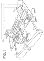
- two flexible strips 8 and 9 are respectively fixed to the ends of an electrode holder 1 and to a fixed support 7 by their other end; these strips in the rest position are perpendicular to the planes of the electrode holder 1 and of the fixed support 7 and serve as a support means allowing the translation of the electrode holder.
- An axis 4, coils 10, 12, 16 and 18 supplied respectively by current sources 11, 13, 17 and 19 are integral with the fixed support 7 which is not shown in this figure.
- a light source6, a photo- detector 23, AND gates, P 1 to P n , and a memory 24 are also integral with this fixed support 7;
- the electrode holder 1 has n electrodes e 1 to having a first end integral with the electrode holder 1 and a second in contact with an electro-sensitive paper (not shown). These electrodes e i to have a non-pitted zone symbolizing an electrical conductor and a pitted zone symbolizing an insulator making it possible to electrically isolate the electrodes from each other.
- Each gate P j receives on a first input an output signal from a memory 24 and on a second input the output signal from a photodetector 23.
- the electrode holder 1 also comprises two supports 15 and 21 of respective soft iron cores 14 and 20. These soft iron cores are subjected to a magnetic field created by the autonomous coils 10 and 12 for the core 14, and 16 and 18 for the core 20; these four coils thus represented symbolize four coils surrounding their respective iron core around which they are arranged. These two identical sets make it possible to make small translations of the electrode holder 1 which will be explained below.
- a rod 3 which can pivot around the fixed axis 4, supports at a first end a plate 5 pierced with k holes t 1 to t k .
- the rotational movement of this rod 3 is linked to the small translations of the electrode holder 1 because the second end of this rod 3 partially surrounds an axis 2, integral with the electrode holder 1.
- the light source 6 illuminates the plate 5 whose the holes make it possible to successively excite the photo-detector 23 during small translations of the electrode holder 1.
- the printing of the k-1 other characters is carried out during small transformations of the electrode holder 1.
- This electrode holder 1 in fact moves to the right or to the left from its equilibrium position, due to the flexible lamellae 8 and 9 which connect it to the fixed support 7; these small translations are substantially rectilinear because their amplitude is small compared to the length of the strips 8 and 9.
- the small translations to the right are controlled by the magnetic field of the coils 10 and 16 respectively excited by the current sources 11 and 17.
- the small translations to the left are controlled by the magnetic field of the coils 12 and 18 respectively excited by the current sources 13 and 19.
- the rod 3 drives the plate 5 in its rotational movement.
- the interval between each hole of the plate 5 is equal to hx 0.125 mm, h being the mechanical amplification equal to the ratio of the distance separating each hole of the plate 5 from the axis 4 and that separating the axes 4 and 2.
- the uniform movement is obtained from the currents supplied by the current sources 11 and 13 on the one hand and 17 and 19 on the other hand, the timing diagrams of which are shown in the following figure.
- a signal a symbolizes the current supplied by the current sources 11 and 17, and a signal b symbolizes the current supplied by the current sources 13 and 19.
- the coils 10 and 16 are suddenly excited by the signal a, which represents a current of value l 0 constant until the instant t 1 , then by a current of value l 1 until the instant t 3 .
- the decrease in the value of the excitation current of these coils decreases the speed of translation to the right of the electrode holder 1; this braking is accentuated by the signal b representing a current of value 1 2 exciting the coils 12 and 18 between the instants t 2 and t 4 in a suitable direction so that the magnetic field created by this current produces an action which opposes the previous one.
- the cycle is reproduced but for a translation to the left.
- this printing process is also applicable to a reading device of the series-parallel type.
- this reading comprises n photosensitive elements which can read k consecutive points during a translation at constant speed of the reading device. It also includes precise identification means constituted by a clock sampling the readings.
- the invention is not limited to the embodiment described and shown, in particular the device can be produced according to the following variations.
- the means for controlling the small translations of the electrode holder 1 may consist of a single soft iron core provided with its two coils excited by their respective current source.
- the means for locating the positioning of each character to be printed consisting of the rod 3 and of the plate 5 associated with an optical reader can be replaced by an optical reader associated with two parallel test patterns each consisting of alternating black and white lines of same width, one of the sights being integral with the electrode holder 1 and the other fixed.
- the lines of one pattern being parallel to those of the other, the optical reader will deliver an electrical signal at each coincidence of the black and white lines of the two patterns.
- the width of the lines must be 0.062 5 mm (that is to say equal to half the space between two points to be printed).
- These means of locating the positioning of each character to be printed can also consist of a test pattern, comprising black lines spaced 0.125 mm apart, associated with an optical reader.
- Such printing devices are particularly usable in fax machines.
Landscapes
- Printers Or Recording Devices Using Electromagnetic And Radiation Means (AREA)
- Facsimile Scanning Arrangements (AREA)
- Facsimiles In General (AREA)
- Character Input (AREA)
Description
- La présente invention concerne des dispositifs d'impression du type série-parallèle, et en particulier ceux permettant d'impressionner un papier électrosensible d'imprimante.
- Des imprimantes du type série-parallèle, comportant un nombre N de stylets imprimant chacun simultanément une suite de n points consécutifs par ligne, sont bien connues.
- Ces imprimantes comportent un dispositif d'impression possédant un nombre déterminé d'électrodes. Le dispositif d'impression est solidaire d'un porte-électrodes et est déplaçable en translation sur un guide, dans un mouvement horizontal alternatif à l'aide d'un mécanisme de translation généralement réalisé à l'aide d'une bielle et d'une manivelle.
- Dans le cas des télécopieurs, l'impression d'une ligne d'une feuille de papier de format A4 nécessite, selon l'avis T4 du C.C.I.T.T, 1 728 points à imprimer en une durée de l'ordre de 30 ms, la distance entre chaque point de 0, 125mm étant affectée d'une tolérance de ± 0,015 mm ; les imprimantes de type série-parallèle connues ne sont ni suffisamment rapides, ni suffisamment précises pour réaliser ce type d'impression, principalement à cause de leur mécanisme de translation dont la vitesse se trouve limitée par l'inertie et le frottement des pièces en mouvement et des jeux qu'il est nécessaire de compenser.
- La présente invention a pour objet de remédier à ces inconvénients.
- Selon l'invention, un dispositif d'impression de type série-parallèle, permettant d'imprimer des lignes de m caractères (m = kn avec k et n entiers positifs supérieurs à 1) sur un papier électrosensible, comportant, n (n entier positif) électrodes solidaires d'un porte-électrodes, des moyens de support permettant la translation du porte-électrodes selon au moins deux directions opposées d'une ligne, les n électrodes pouvant imprimer simultanément, chacune pouvant en outre imprimer une suite de k (k = m/n) caractères consécutifs lors d'une translation du porte-électrodes correspondant à l'impression d'une ligne, et des moyens de repérage du positionnement de chaque caractère à imprimer lors de cette translation, est caractérisé par des moyens de translation qui comprennent, pour déplacer le porte-électrodes dans chacune des directions, au moins une première bobine reliée à une première source de courant pour commander et contrôler le déplacement du porte-électrodes, au moins une deuxième bobine reliée à une deuxième source de courant pour freiner le déplacement du porte-électrodes, et au moins un noyau de fer doux, solidaire du porte-électrodes sensible aux champs magnétiques créés par les première et deuxième bobines lorsqu'elles sont alimentées par les première et deuxième sources de courant et par rapport auxquelles il peut se. déplacer, l'intensité du courant circulant dans la première bobine ayant une première valeur au début du déplacement et une deuxième valeur inférieure à la première valeur de courant en cours de déplacement, et le courant circulant dans la deuxième bobine étant appliqué après l'application de la deuxième valeur du courant dans la première bobine de façon que le déplacement dans chaque direction, l'alimentation desdites bobines étant permutée, puisse être réalisé à vitesse à peu près constante pendant la durée d'impression des k caractères consécutifs.
- Les avantages obtenus grâce au dispositif d'impression de l'invention résultent du fait que le mouvement de translation du porte-électrodes est obtenu directement par l'action d'un champ magnétique sur un noyau de fer doux solidaire du porte-électrodes, ce qui supprime de ce fait le relayage mécanique à bielle-manivelle des imprimantes de l'art antérieur et qui procure au dispositif une plus grande souplesse de commande et une plus grande vitesse d'impression puisque, les inerties mécaniques et les frottements sont notablement diminués. Comme le nombre de pièces mécaniques en mouvement se trouve considérablement réduit et limité en fait à l'unique porte-électrodes, la fiabilité du dispositif se trouve accrue et son entretien facilité. La réduction des pièces mécaniques mise en oeuvre conduit également à l'abaissement du prix de revient.
- D'autre part, l'utilisation d'au moins deux bobines pour assurer le déplacement du porte-électrodes permet d'obtenir encore une plus grande souplesse de fonctionnement qui ne saurait être obtenue par l'utilisation d'une seule bobine car les commandes séparées des deux bobines qui en résultent permettent de déterminer avec une grande précision les instants de freinage du porte-électrodes et d'assurer par conséquent une meilleure régulation de la vitesse de déplacement du porte-électrodes.
- L'invention sera mieux comprise et d'autres caractéristiques apparaîtront à l'aide de la description et des dessins s'y rapportant sur lesquels :
- la figure 1 est un schéma d'un mode de réalisation du dispositif selon t'invention ;
- la figure 2 représente un chronogramme de signaux permettant d'expliquer le fonctionnement du dispositif de la figure 1.
- Sur la figure 1, par l'une de leur extrémité deux lamelles souples 8 et 9 sont respectivement fixées aux extrémités d'un porte-électrodes 1 et sur un support fixe 7 par leur autre extrémité ; ces lamelles en position de repos sont perpendiculaires aux plans du porte-électrodes 1 et du support fixe 7 et servent à un moyen de support permettant la translation du porte-électrodes.
- Un axe 4, des bobines 10, 12, 16 et 18 alimentées respectivement par des sources de courant 11, 13, 17 et 19 sont solidaires du support fixe 7 ce qui n'est pas représenté sur cette figure. De même une source lumineuse6, un photo- détecteur 23, des portes ET, P1 à Pn, et une mémoire 24 sont également solidaires de ce support fixe 7 ;
- Le porte-électrodes 1 comporte n électrodes e1 à en ayant une première extrémité solidaire du porte-électrodes 1 et une seconde en contact avec un papier électrosensible (non représenté). Ces électrodes ei à en comportent une zone non piquetée symbolisant un conducteur électrique et une zone piquetée symbolisant un isolant permettant d'isoler électriquement les électrodes entre elles. La partie conductrice de chaque électrodes ej (j = 1 .. n) reçoit le signal de sortie de la porte ET, Pj (j = 1 .. n) correspondante. Chaque porte Pj reçoit sur une première entrée un signal de sortie d'une mémoire 24 et sur une seconde entrée le signal de sortie d'un photodétecteur 23.
- Le porte-électrodes 1 comporte également deux supports 15 et 21 de noyaux de fer doux respectifs 14 et 20. Ces noyaux de fer doux sont soumis à un champ magnétique créé par les bobines autonomes 10 et 12 pour le noyau 14, et 16 et 18 pour le noyau 20 ; ces quatre bobines ainsi représentées symbolisent quatre bobines entourant leur noyau de fer respectif autour duquel elles sont disposées. Ces deux ensembles identiques permettent de réaliser de petites translations du porte-électrodes 1 qui seront explicitées plus loin.
- Une tige 3, pouvant pivoter autour de l'axe fixe4, supporte à une première extrémité une plaque 5 percée de k trous t1 à tk. Le mouvement de rotation de cette tige 3 est liée aux petites translations du porte-électrodes 1 du fait que la seconde extrémité de cette tige 3 entoure partiellement un axe 2, solidaire du porte-électrodes 1. La source lumineuse 6 éclaire la plaque 5 dont les trous permettent d'exciter successivement le photo-détecteur 23 lors des petites translations du porte-électrodes 1.
- Le dispositif d'impression de type série-parallèle ainsi décrit, permet d'imprimer simultanément n caractères grâce à ses n électrodes e1 à en ; cette impression est répétée k fois lors de petites translations du porte-électrodes 1 effectuées à vitesse approximativement constante. En conséquence l'impression d'une ligne comportera n × k = m caractères.
- Dans la présente réalisation n = 144, k = 12 et m = 1 728.
- En effet l'impression simultanée des n caractères est réalisée par les n électrodes e1 à en lorsqu'elles reçoivent chacune un signal électrique provenant de leur porte Pj (j = 1 .. n) correspondante (du fait que la seconde extrémité de ces électrodes est en contact avec le papier électrosensible).
- L'impression des k-1 autres caractères est réalisée lors des petites'translations du porte-électrodes 1. Ce porte-électrodes 1 en effet se déplacer vers la droite ou vers la gauche de sa position d'équilibre, du fait des lamelles souples 8 et 9 qui le relient au support fixe 7 ; ces petites translations sont sensiblement rectilignes car leur amplitude est faible par rapport à la longueur des lamelles 8 et 9. Les petites translations vers la droite sont commandées par le champ magnétique des bobines 10 et 16 respectivement excitées par les sources de courant 11 et 17. Les petites translations vers la gauche sont commandées par le champ magnétique des bobines 12 et 18 respectivement excitées par les sources de courant 13 et 19.
- Lors du déplacement du porte-électrodes 1, la tige 3 entraîne la plaque 5 dans son mouvement de rotation. Lorsque le faisceau lumineux émis par la source 6 traverse un trou de la plaque 5 le photodétecteur 23 émet un signal logique qui ouvre les portes Pj (j = 1 .. n), permettant aux informations stockées dans la mémoire 24 d'être appliquées sur les électrodes ej (j = 1 .. n) correspondantes. Ici l'intervalle entre chaque trou de la plaque 5 est égal à h x 0,125 mm, h étant l'amplification mécanique égale au rapport de la distance séparant chaque trou de la plaque 5 de l'axe 4 et de celle séparant les axes 4 et 2.
- Le mouvement uniforme est obtenu à partir des courants fournis par les sources de courant 11 et 13 d'une part et 17 et 19 d'autre part dont les chronogrammes sont représentés sur la figure suivante.
- Sur la figure 2 un signal a symbolise le courant fourni par les sources de courant 11 et 17, et un signal b symbolise le courant fourni par les sources de courant 13 et 19.
- A l'instant to les bobines 10 et 16 sont excitées brutalement par le signal a, qui représente un courant de valeur l0 constant jusqu'à l'instant t1, puis par un courant de valeur l1 jusqu'à l'instant t3. La diminution de la valeur du courant d'excitation de ces bobines diminue la vitesse de translation vers la droite du porte-électrodes 1 ; ce freinage est accentué par le signal b représentant un courant de valeur 12 excitant les bobines 12 et 18 entre les instants t2 et t4 dans un sens convenable pour que le champ magnétique créé par ce courant produise une action qui s'oppose à la précédente. Entre les instants t5 et tg le cycle se reproduit mais pour une translation vers la gauche.
- Une amélioration du mouvement uniforme du porte-électrodes 1 pendant la durée d'impression d'une ligne, est obtenue en imposant une translation de ce porte-électrodes 1 entre les deux positions extrêmes de 2,5 mm alors que l'impression des 12 caractères ne nécessite qu'une translation de 1,5 mm.
- Il est à noter que si l'écriture d'une ligne quelconque s'effectue pendant une translation de gauche à droite, celle de la suivante s'effectue lors de la translation suivante de droite à gauche.
- L'expérience montre et le calcul confirme que ces courants associés à la résistance des lamelles souples 8 et 9 procurent une translation s'effectuant à vitesse sensiblement constante dans chaque sens pendant la durée de l'impression des k caractères
- Il est à noter que ce procédé d'impression est également applicable à un dispositif de lecture de type série-parallèle. Dans ce cas ce dispositif de lecture comporte n éléments photosensibles pouvant lire k points consécutifs lors d'une translation à vitesse constante du dispositif de lecture. Il comporte également des moyens de repérage précis constitués par une horloge échantillonnant les lectures.
- L'invention n'est pas limitée au mode de réalisation décrit et représenté, en particulier le dispositif peut être réalisé selon les variations suivantes.
- Les moyens permettant de commander les petites translations du porte-électrodes 1 peuvent être constitués d'un seul noyau de fer doux munis de ses deux bobines excitées par leur source de courant respective.
- Les moyens de repérage du positionnement de chaque caractère à imprimer constitués de la tige 3 et de la plaque 5 associée à un lecteur optique peuvent être remplacés par un lecteur optique associé à deux mires parallèles constituées chacune d'une alternance de traits noirs et blancs de même largeur, l'une des mires étant solidaires du porte-électrodes 1 et l'autre fixe. Les traits d'une mire étant parallèles à ceux de l'autre, le lecteur optique délivrera un signal électrique à chaque coïncidence des traits noirs et blancs des deux mires. Cependant dans ce cas la largeur des traits doit être de 0,062 5 mm (c'est-à-dire égale à la moitié de l'espace entre deux points à imprimer).
- Ces moyens de repérage du positionnement de chaque caractère à imprimer peuvent également être constitués d'une mire, comportant des traits noirs espacés de 0,125 mm, associée à un lecteur optique.
- De tels dispositifs d'impression sont notamment utilisables dans les télécopieurs.
Claims (5)
Applications Claiming Priority (2)
| Application Number | Priority Date | Filing Date | Title |
|---|---|---|---|
| FR7827921 | 1978-09-29 | ||
| FR7827921A FR2437298A1 (fr) | 1978-09-29 | 1978-09-29 | Dispositif d'impression du type serie-parallele pour imprimante et telecopieur comportant un tel dispositif |
Publications (2)
| Publication Number | Publication Date |
|---|---|
| EP0010021A1 EP0010021A1 (fr) | 1980-04-16 |
| EP0010021B1 true EP0010021B1 (fr) | 1983-01-26 |
Family
ID=9213183
Family Applications (1)
| Application Number | Title | Priority Date | Filing Date |
|---|---|---|---|
| EP79400654A Expired EP0010021B1 (fr) | 1978-09-29 | 1979-09-18 | Dispositif d'impression du type série-parallèle pour imprimante et télécopieur comportant un tel dispositif |
Country Status (5)
| Country | Link |
|---|---|
| US (1) | US4294551A (fr) |
| EP (1) | EP0010021B1 (fr) |
| JP (1) | JPS5549268A (fr) |
| DE (1) | DE2964622D1 (fr) |
| FR (1) | FR2437298A1 (fr) |
Families Citing this family (4)
| Publication number | Priority date | Publication date | Assignee | Title |
|---|---|---|---|---|
| US4497682A (en) * | 1981-05-29 | 1985-02-05 | Monarch Marking Systems, Inc. | Hand-held electrically selectable labeler |
| US4407692A (en) * | 1981-05-29 | 1983-10-04 | Monarch Marking Systems, Inc. | Hand-held electrically selectable labeler |
| US4556442A (en) * | 1981-05-29 | 1985-12-03 | Monarch Marking Systems, Inc. | Hand-held electrically selectable labeler |
| US4941405A (en) * | 1987-12-16 | 1990-07-17 | Dataproducts Corporation | Driving mechanism for reciprocating print shuttle |
Family Cites Families (9)
| Publication number | Priority date | Publication date | Assignee | Title |
|---|---|---|---|---|
| GB1260570A (en) * | 1968-09-10 | 1972-01-19 | New Zealand Inv S Dev Authorit | Improvements in or relating to recorders for recording numerous inputs of data |
| DE2145245A1 (de) * | 1971-09-10 | 1973-03-15 | Triumph Werke Nuernberg Ag | Druckvorrichtung |
| US3802544A (en) * | 1972-04-28 | 1974-04-09 | Centronics Data Computer | High speed dot matrix printer |
| IT1000641B (it) * | 1973-12-28 | 1976-04-10 | Olivetti & Co Spa | Unita di stampa elettrotermica di tipo perfezionato |
| NL161279C (nl) * | 1974-03-08 | 1980-01-15 | Philips Nv | Besturingsinrichting voor een matrixdrukker. |
| FR2283003A1 (fr) * | 1974-07-25 | 1976-03-26 | Sagem | Perfectionnements apportes aux imprimantes |
| US3941051A (en) * | 1974-08-08 | 1976-03-02 | Printronix, Inc. | Printer system |
| FR2300678A1 (fr) * | 1975-02-13 | 1976-09-10 | Logabax | Dispositif d'impression pour imprimantes rapides |
| FR2368361A1 (fr) * | 1976-10-20 | 1978-05-19 | Oki Electric Ind Co Ltd | Imprimante par points |
-
1978
- 1978-09-29 FR FR7827921A patent/FR2437298A1/fr active Granted
-
1979
- 1979-09-18 DE DE7979400654T patent/DE2964622D1/de not_active Expired
- 1979-09-18 EP EP79400654A patent/EP0010021B1/fr not_active Expired
- 1979-09-25 US US06/078,804 patent/US4294551A/en not_active Expired - Lifetime
- 1979-09-29 JP JP12631379A patent/JPS5549268A/ja active Pending
Also Published As
| Publication number | Publication date |
|---|---|
| EP0010021A1 (fr) | 1980-04-16 |
| FR2437298A1 (fr) | 1980-04-25 |
| FR2437298B1 (fr) | 1983-09-16 |
| US4294551A (en) | 1981-10-13 |
| DE2964622D1 (en) | 1983-03-03 |
| JPS5549268A (en) | 1980-04-09 |
Similar Documents
| Publication | Publication Date | Title |
|---|---|---|
| US2659652A (en) | High-speed multiplex recording apparatus | |
| EP0096677A1 (fr) | Dispositif automatique d'analyse et sa commande pour des applications de traitement opto-mécanique | |
| JPH09189873A (ja) | マルチビーム走査方法およびマルチビーム走査装置 | |
| EP0010021B1 (fr) | Dispositif d'impression du type série-parallèle pour imprimante et télécopieur comportant un tel dispositif | |
| GB2220384A (en) | Identifying cassettes used in selective printing machines | |
| US4609946A (en) | Facsimile apparatus and duplicator | |
| US2575742A (en) | Device for copying records on a proportional scale | |
| US4631432A (en) | Linear motor facsimile machine | |
| US518534A (en) | Johan w | |
| US2294645A (en) | Printing plate | |
| EP0210927A1 (fr) | Résolveur pour repérer la position angulaire d'un organe tournant | |
| CA1074449A (fr) | Dispositif d'inscription de symboles graphiques et alphanumeriques pour table tracante | |
| US4211493A (en) | Impact printing apparatus | |
| FR2477971A1 (fr) | Dispositif enregistreur a jet de liquide | |
| US4106029A (en) | Device for recording measuring values | |
| EP0168474A1 (fr) | Organe indicateur de position pour un dispositif commande electriquement tel qu'une imprimante. | |
| EP0021966B1 (fr) | Imprimante à radar ultrasonique | |
| US2067489A (en) | Photoelectric engraving | |
| US461575A (en) | hereick | |
| US2743398A (en) | Electromagnetic translating device | |
| EP0156799A1 (fr) | Machine de fac-similes a usages multiples | |
| US759177A (en) | Watchman's time-recorder. | |
| US3969998A (en) | Printing actuator | |
| US849276A (en) | Automatic street-indicator for electric railways. | |
| US839436A (en) | Curve-drawing instrument. |
Legal Events
| Date | Code | Title | Description |
|---|---|---|---|
| PUAI | Public reference made under article 153(3) epc to a published international application that has entered the european phase |
Free format text: ORIGINAL CODE: 0009012 |
|
| AK | Designated contracting states |
Designated state(s): DE GB NL |
|
| 17P | Request for examination filed | ||
| GRAA | (expected) grant |
Free format text: ORIGINAL CODE: 0009210 |
|
| AK | Designated contracting states |
Designated state(s): DE GB NL |
|
| REF | Corresponds to: |
Ref document number: 2964622 Country of ref document: DE Date of ref document: 19830303 |
|
| PGFP | Annual fee paid to national office [announced via postgrant information from national office to epo] |
Ref country code: DE Payment date: 19840723 Year of fee payment: 6 |
|
| PGFP | Annual fee paid to national office [announced via postgrant information from national office to epo] |
Ref country code: NL Payment date: 19860930 Year of fee payment: 8 |
|
| PG25 | Lapsed in a contracting state [announced via postgrant information from national office to epo] |
Ref country code: NL Effective date: 19880401 |
|
| NLV4 | Nl: lapsed or anulled due to non-payment of the annual fee | ||
| PG25 | Lapsed in a contracting state [announced via postgrant information from national office to epo] |
Ref country code: DE Effective date: 19880601 |
|
| GBPC | Gb: european patent ceased through non-payment of renewal fee | ||
| PG25 | Lapsed in a contracting state [announced via postgrant information from national office to epo] |
Ref country code: GB Free format text: LAPSE BECAUSE OF NON-PAYMENT OF DUE FEES Effective date: 19881118 |
|
| PLBE | No opposition filed within time limit |
Free format text: ORIGINAL CODE: 0009261 |
|
| STAA | Information on the status of an ep patent application or granted ep patent |
Free format text: STATUS: NO OPPOSITION FILED WITHIN TIME LIMIT |