EP0010041A1 - Verfahren zum Stranggiessen von Metallen, mit Umrühren in der sekundären Kühlungszone - Google Patents
Verfahren zum Stranggiessen von Metallen, mit Umrühren in der sekundären Kühlungszone Download PDFInfo
- Publication number
- EP0010041A1 EP0010041A1 EP79400695A EP79400695A EP0010041A1 EP 0010041 A1 EP0010041 A1 EP 0010041A1 EP 79400695 A EP79400695 A EP 79400695A EP 79400695 A EP79400695 A EP 79400695A EP 0010041 A1 EP0010041 A1 EP 0010041A1
- Authority
- EP
- European Patent Office
- Prior art keywords
- solidification
- metal
- inductor
- well
- magnetic field
- Prior art date
- Legal status (The legal status is an assumption and is not a legal conclusion. Google has not performed a legal analysis and makes no representation as to the accuracy of the status listed.)
- Granted
Links
Images


Classifications
-
- B—PERFORMING OPERATIONS; TRANSPORTING
- B22—CASTING; POWDER METALLURGY
- B22D—CASTING OF METALS; CASTING OF OTHER SUBSTANCES BY THE SAME PROCESSES OR DEVICES
- B22D11/00—Continuous casting of metals, i.e. casting in indefinite lengths
- B22D11/12—Accessories for subsequent treating or working cast stock in situ
- B22D11/122—Accessories for subsequent treating or working cast stock in situ using magnetic fields
Definitions
- the present invention relates to the continuous casting of molten metals, in particular steel. It relates more precisely to the operations of mixing the liquid metal, during solidification in the secondary cooling stage of the casting machine, in order to improve the metallurgical quality of the product obtained.
- the invention relates in particular to the casting of products of elongated section, for example slabs.
- the liquid interior part of the product is therefore substantially in the form of a cone, the base of which corresponds to the free surface of the metal in the mold and the top of which is located at the outlet of the cooling stage. secondary. It is customary to designate this cone by the expression “liquid well” or “solidification well”, and the distance separating the base from the top by "metallurgical height”.
- the mixing in the secondary cooling stage of a continuous casting machine of elongated products, such as slabs can it be carried out by entraining the liquid metal in a horizontal translational movement, this is that is to say directed perpendicular to the pouring axis and propagating from one small face of the product to the other.
- This stirring can also consist of a vertical entrainment of the molten metal extended over the entire width of the cast product (German patent n ° 2,720,391) or on its perimeter (French patents n ° 2,085,261 and n ° 2,104,863).
- the applicant asked the question whether the improvement in metallurgical quality, resulting from an increased proportion of equiaxed solidification structure, was due to the mixing as such, in which case it can be estimated that this means is used to the best of its ability, or if this improvement depends quantitatively on the type of metal drive, that is to say on the directional characteristics of the forced convection movements that are created within the mass in merger, or its extension to most of the product.
- the subject of the invention is a process for the continuous casting of molten metals, in particular steel, for obtaining products of elongated section, such as slabs, process according to which the molten metal at the top during solidification in the secondary cooling stage of the casting machine, has a stirring action exerted at least in the vicinity of the lower end of the solidification well, this stirring is carried out by driving the metal in a direction having at least one vertical component, method characterized in that the entrainment of the molten metal is located on a part of the perimeter of the cast product.
- the present invention therefore consists, in its essential characteristics, of promoting vertical exchanges of molten material, therefore of stimulating a rise in the liquid metal from the bottom of the solidification well, more effectively than by the methods previously mentioned.
- the map of the speeds of movements in a plane parallel to the large faces of the product reveals a horizontal motor drive corridor, that is to say subject directly to the action of the magnetic field and which, therefore, can be described as a “driving zone” or “circulation zone” as opposed to the two more diffuse recirculation regions which are established to ensure the return of the metal, on either side of the central corridor, in a shape reminiscent of that of butterfly wings.
- the invention makes it possible to locate exactly where it is desired, the action of the electromagnetic fields and therefore to obtain the desired result.
- the basic idea of the present invention therefore consists in fetching these small crystals accumulated at the bottom of the well, and available in large quantities, and transporting them to higher levels of the metallurgical height where it is desired to be seen. interrupt basaltic growth in favor of an equiaxed structure.
- the invention is basically an operation of seeding the most disadvantaged regions of the liquid well, with small equiaxial crystals coming from richer regions located at the bottom of the well.
- liquid metal does not have a role here by itself but rather as a vehicle for collecting and transporting solidification germs. Incidentally, it is true, this movement of liquid mass between the bottom of the solidification well and higher regions makes it possible to mix a hot metal with a cooler metal and therefore to homogenize the temperature, which in particular has the effect of reducing the overheating of the upper regions, therefore, to facilitate the growth of the solidification germs which are brought there.
- the electromagnetic stirring in question here consists in subjecting the cast product to the action of a mobile magnetic field, which gives rise in liquid metal to convection movements directed and oriented in the direction of propagation. of the field.
- the mobile magnetic field constitutes for its part a privileged tool for setting work since it allows the control of the brewing itself, by conferring on the user the control of the drive of the metal, therefore the control of the convection movements which he wishes to develop there.
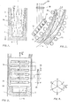
- the poured metal already solidified is designated by 1, 2 the liquid well in the course of solidification, 3 the solidification front without distinguishing that relating to the large faces of the slab from that relating on the small faces, 4 the bottom of the solidification well at 5 the pouring axis which moreover merges with the axis of the slab.
- X indicates the number of the figure which shows them for the first time.
- V B vector Velocity of the magnetic induction field B
- liquid metal well is shown in the figures by way of illustration without it being possible to assume quantitatively the actual relationships existing between the metallurgical height and the transverse dimensions of the cast product.
- the bottom of the solidification well is in the form of a narrow and deep valley oriented parallel to the plane of the large faces and of which the slopes are formed. by the solidification fronts relating to these large faces.
- the closure of the well that is to say the end of solidification, then occurs by gradual approximation of the two slopes, with no significant contribution from the solidification fronts of the small faces, unlike less asymmetrical formats, such as round or square , in which complete solidification results from an equivalent and simultaneous progression of the entire periphery.
- the ascent of the liquid metal from the bottom of the solidification well can be obtained by putting the metal into circulation, which can have several different configurations:
- this method of mixing is essentially characterized by predominantly vertical movements, occurring over the entire width of the solidification well 2.
- the movements create a rising circulation 16 along a solidification front of large face followed by a downward circulation 17 symmetrical on the opposite slope.
- the assembly is in the form of a sheet closed on itself, occupying the entire width of the liquid well 2, and rotating around its axis, perpendicular to the pouring axis 5, each current loop defining a movement plane parallel to the small faces of the slab.
- the driving zone as it was defined previously, can be either the upward or downward part of the sheet.
- such a movement is obtained by means of a sliding magnetic field whose direction of propagation B is vertical and which acts over the entire width of the solidification well 2
- the mean direction of the field lines is preferably perpendicular to the plane of the large faces of the slab.
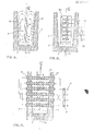
- Such a magnetic field can be created by polyphase static inductors of known type, two examples of which are given here with reference to the following figures: a one-piece inductor 21 placed behind the support rollers 22 (FIGS. 2 and 3), or an inductive assembly 41 constituted by the functional association of several identical unit inductors structurally independent of each other, and each placed inside of the tubular support rollers 43 (FIGS. 4, 5, 6 and 7).
- the one-piece inductor 21 of Figures 2 or 3 has a structure similar to that of a linear induction motor stator. It consists of a flat cylinder head 23 made of laminated sheets having, on its face facing the cast product, notches parallel to each other and perpendicular to the plane of the sheets.
- These notches are occupied by electrical conductors 24, generally copper bars.
- the inductor is arranged, in accordance with the invention, facing one of the large faces of the slab and so that the conductive bars 24 are perpendicular to the casting axis 5. As shown in FIG. 3, these bars are connected together in pairs in series so that the electric current flows there in opposite directions.
- Each bar is spaced from its partner by a number of notches equal to the number of phases of the power supply so as to constitute overall a well known nested type winding.
- connection box 20 a polyphase, for example three-phase power supply, symbolically represented at 25 in the figures, by the three phases R, S, T and the neutral N, so as to generate a magnetic field sliding vertically along the axis 5.
- a polyphase for example three-phase power supply, symbolically represented at 25 in the figures, by the three phases R, S, T and the neutral N, so as to generate a magnetic field sliding vertically along the axis 5.
- this inductor is, as clearly shown in FIG. 3, that the length of the bars 24 is at least equal to the width of the solidification well 2, so that the magnetic field produced acts well over the entire width. It should be noted that, in order not to overload the figure, the support rollers have not been shown. The electromagnetic action at a point weakening with the distance from this point to the inductor, the "driving area" within the liquid metal, as defined in the previous lines, is of course the most next to the inductor.
- the mixing mode of Figure 2 is obtained by a propagation V B of the field oriented from bottom to top.
- This direction of propagation is achieved by means of the connection mode of the inductor 21 to the power supply 25 as shown diagrammatically in FIG. 3.
- the letter R, S or T representative of the phase to which it is connected, and possibly surmounted by a line R, S and T indicating the relative direction of the electric current flowing through it.
- the bars marked R and R constitute a pair mounted in series, connected to the phase R of the supply and are respectively traversed by the same current flowing in opposite directions, for example from left to right for the R bar and from right to left for the R bar.
- the mode of circulation of the liquid metal illustrated in FIG. 2 is reversible, which can be obtained either by placing the inductor 21 facing the other large face of the slab while retaining the same direction of propagation of the field, or more simply by reversing the direction of sliding of the magnetic field without modifying the location of the inductor, by inversion of two phases of the electrical supply.
- Figure 8 schematically translating on a circle the three phases R, S, T of the power supply offset from each other by 120 °, as well as their "inverses".
- R, S, T, by rotating vectors constitutes a convenient means for quickly finding, from a given connection mode of the inductor, the sliding direction of the magnetic field which it creates.
- the method of stirring the metal of FIG. 2 can also be obtained by placing the inductor 21 opposite the other face of the slab and by reversing the direction of sliding of the field there. In this case, it is well understood, it is the descending part 17 of the ply which is driving.
- zones 16 and 17 are both driving, one ascending, the other descending. To do this, it suffices to complete the system with a second inductor arranged symmetrically with the first, facing the other large face of the slab and creating a sliding magnetic field in an opposite direction.
- the direction of sliding of the field is the same on the two inductors, in which case a recirculation zone is created in the center of the liquid well which separates the two direct drive motor zones of the same direction, located along each of the fronts of solidification of the large faces.
- the induction device 41 is this time constituted by the association of several identical elementary inducing units 42, for example six in number and each placed inside a tubular support roller 43.
- each inductor unit consists of coils 44 arranged side by side, one after the other, around a common horizontal axis so as to cover all of the width of the orame.
- Figures 5, 6, and 7 respectively show three possible variants of implementation.
- only six coils have been shown per inductor unit.
- the coils belonging to the same inductor unit can be mounted in parallel or in 3 ie.
- the reversal of the electric current direction between two coils can be carried out, as it is, by inversion, either of the winding direction of the windings, scit du of connection.
- a system ar ogue is thus constructed with a plurality of inductors with sliding field, each consisting of a vertical succession of coils, does not change: as before, each inductor unit 42 is connected to a single phase of the power supply.
- the mounting of the coils belonging to the same inductor unit does not change either: it is such that the electric current flows in opposite directions in two immediately adjacent coils.
- the only difference is the relative mounting of coils of the same rank on separate inductor units so that the electric current now flows in the same direction.
- the third variant is illustrated in FIG. 7.
- inductor units 42 connected to the same phase of the power supply 25 can either be connected in series, as shown in the figures, or in parallel.
- planar movements being all the more easy as the available surface is more important, it is understood that, taking into account the format of the cast product, this mode of mixing, whose circulation loops occupy the half-width of the well, is more advantageous than the preceding stirring modes, the loops of which close according to the thickness of the liquid well.
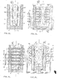
- the vertical driving zone 96 rising in the case of the figure, can be obtained by means of a magnetic field sliding vertically but whose action remains this time localized in the central region of the well.
- FIGS. 10 and II below show two exemplary embodiments of the means for producing such a field.
- the first example (FIG. 10) consists in using a monobloc inductor 101, the structure, the arrangement of which on the casting machine, and the implementation are identical to those of the inductor of FIG. 3, but the dimensions transverse are reduced so as to limit its action to the central region of the liquid well 2.
- the second example, illustrated in FIG. 11, takes up the principle of the inductor 41 made up of several elementary inductive units 42 arranged inside the support rollers 43.
- a system similar to those described above is then produced but which is distinguishes, as can be seen, from the fact that only the coils 44 located opposite the central region of the liquid well 2 are activated on each inductor unit 42.
- the assembly of the coils can be interchanged any of the three variants described above and illustrated respectively in FIGS. 5, 6 and 7.
- planar movements parallel to the plane of the large faces consists in this time of creating two vertical driving zones each located opposite the solidification fronts of the small faces of the product.
- these two motor zones are reverse, a simple circulatory regime is established and well organized around a perperdicular axis with large faces and by the median axis 5 (figure 1).
- the median axis 5 (figure 1).
- movements become more complicated if the motor areas are brought together axis 5, because it creates recirculation zones 127 and confined in the narrow regions located between a motor zone and the solidification front of the smallest nearest face.
- Such a drive mode can be obtained, as shown in the following two figures (13 and 14), by means of vertically sliding magnetic fields, produced by inductors arranged facing at least one large face of the slab and placed laterally on both sides d. the axis of casting.
- These inductors can be of the "monobloc" type ref. 131 and 131 ') therefore arranged behind the support rollers, completely analogous to the inductor shown in the but connected, as shown in figure 13, to the power supply 25 to create two vertically sliding magnetic fields oriented in opposite directions.
- inductors can also be formed by the units 42 previously described, in which case, as shown in the only a few coils 44 per unit 42 will be activated, arranged tively outside and on either side of the central region of the liquid well 2. big face.
- another configuration of the movements of circulation of the liquid metal capable of ensuring the transport of the crystals between the bottom of the liquid well and the higher regions, consists in creating, as shown in FIG. 16, a motor zone 166 parallel to the large faces of the product, directed obliquely and oriented from the bottom up. There is thus formed on either side of the motor zone 166, a lower recirculation zone 167 and an upper recirculation zone 168.
- the crystals coming from the lower region 167 penetrate through the lower end of the direct drive zone 166 and exit from it by the upper end, taking the easiest path, that is to say by engaging in the upper region 168.
- the from S passing from the half loop opposite without having to operate a abrupt change of direction.
- the desirable orientation for the motor area would be horizontal, as is customary.
- this increasing inclination correlatively disadvantages the possibilities of material exchange between the bottom of the well and the higher levels and therefore goes against the desired result.
- This compromise is characterized by a metal entrainment parallel to the large faces and whose direction of propagation has a non-zero angle with the horizontal, and preferably between around 30 and 60 °.
- the direction of metal drive can no longer be reversible, as in the previous brewing modes, but necessarily oriented from bottom to top.
- the system remains symmetrical with respect to the casting axis 5 as regards the direction of the drive.
- the first variant is produced, in accordance with FIG. 17 by means of a one-piece inductor 171, similar in all points to the inductor shown in FIG. 10, except as regards its inclined orientation relative to the casting axis 5.
- the advantage of this variant lies essentially in the fact that the inductor being independent of the constituent members of the casting machine, it can be given the best inclination 1. 3 .
- each unit 42 has a functional autonomy and creates a horizontally sliding magnetic field along the generators of the rollers. To do this, each unit 42 is no longer, as in the previous cases, connected to a single phase of the power supply 25, but to the three phases simultaneously and the internal wiring of the coils 44, as well as the winding directions. , are carried out according to the scheme of usual practice.
- the system according to the invention is however characterized by the fact that the inducing units have a phase shift between them, so that a succession of coils of the same rank, taken one after the other on units different, constitutes, as in the case of FIGS. 5 and 6, an inductor with a magnetic field sliding vertically from bottom to top
- the combined effect of the horizontal displacement field with the vertically moving field V B identifies with the effect of a single field propagating obliquely according to their result
- the actual position of the inductor over the metallurgical height is not limited to that visible in the figures. The user can act on this position so that the movements caused reach the immediate vicinity of the bottom of the solidification well.
- the setting in motion of the liquid metal at the bottom of the well depends not only on the height position of the inductor but also on its power, electreomagnetic on metal.
Landscapes
- Engineering & Computer Science (AREA)
- Mechanical Engineering (AREA)
- Continuous Casting (AREA)
Priority Applications (1)
| Application Number | Priority Date | Filing Date | Title |
|---|---|---|---|
| AT79400695T ATE1884T1 (de) | 1978-10-05 | 1979-10-01 | Verfahren zum stranggiessen von metallen, mit umruehren in der sekundaeren kuehlungszone. |
Applications Claiming Priority (2)
| Application Number | Priority Date | Filing Date | Title |
|---|---|---|---|
| FR7828726 | 1978-10-05 | ||
| FR7828726A FR2437900A1 (fr) | 1978-10-05 | 1978-10-05 | Procede de coulee continue des metaux avec brassage dans la zone du refroidissement secondaire |
Publications (2)
| Publication Number | Publication Date |
|---|---|
| EP0010041A1 true EP0010041A1 (de) | 1980-04-16 |
| EP0010041B1 EP0010041B1 (de) | 1982-12-01 |
Family
ID=9213482
Family Applications (1)
| Application Number | Title | Priority Date | Filing Date |
|---|---|---|---|
| EP79400695A Expired EP0010041B1 (de) | 1978-10-05 | 1979-10-01 | Verfahren zum Stranggiessen von Metallen, mit Umrühren in der sekundären Kühlungszone |
Country Status (4)
| Country | Link |
|---|---|
| EP (1) | EP0010041B1 (de) |
| AT (1) | ATE1884T1 (de) |
| DE (1) | DE2964155D1 (de) |
| FR (1) | FR2437900A1 (de) |
Cited By (5)
| Publication number | Priority date | Publication date | Assignee | Title |
|---|---|---|---|---|
| EP0092126B1 (de) * | 1982-04-19 | 1986-03-26 | Asea Ab | Verfahren zum Umrühren der nicht erstarrten Bereiche in einem Giessstrang |
| US4699205A (en) * | 1984-04-06 | 1987-10-13 | Voest-Alpine Aktiengesellschaft | Method of establishing a turbulent motion of molten steel within a strand guide |
| DE102014105870A1 (de) * | 2014-04-25 | 2015-10-29 | Thyssenkrupp Ag | Verfahren und Vorrichtung zum Dünnbrammen-Stranggießen |
| CN106925762A (zh) * | 2015-12-29 | 2017-07-07 | 北京有色金属研究总院 | 一种高剪切强电磁搅拌熔体处理的装置和方法 |
| CN116213664A (zh) * | 2023-03-27 | 2023-06-06 | 东北大学 | 一种连铸二冷区分节辊式多模式电磁搅拌控流装置 |
Families Citing this family (1)
| Publication number | Priority date | Publication date | Assignee | Title |
|---|---|---|---|---|
| FR2528739B1 (fr) * | 1982-06-18 | 1985-08-02 | Siderurgie Fse Inst Rech | Procede et installation de brassage electromagnetique de brames metalliques, notamment d'acier, coulees en continu |
Citations (7)
| Publication number | Priority date | Publication date | Assignee | Title |
|---|---|---|---|---|
| FR2068803A1 (de) | 1969-12-12 | 1971-09-03 | Aeg Elotherm Gmbh | |
| FR2085261A1 (de) | 1970-04-02 | 1971-12-24 | Centrifugation Et | |
| FR2104863A1 (de) | 1970-08-20 | 1972-04-21 | Republic Steel Corp | |
| FR2185468A1 (de) | 1972-05-24 | 1974-01-04 | Philips Nv | |
| DE2401145A1 (de) | 1973-04-18 | 1974-10-31 | Nippon Steel Corp | Verfahren und vorrichtung zum kontinuierlichen giessen |
| GB1405312A (en) | 1972-06-08 | 1975-09-10 | Siderurgie Fse Inst Rech | Machines for the continuous casting of metals |
| DE2720391A1 (de) | 1976-05-21 | 1977-12-01 | Asea Ab | Anordnung beim stranggiessen |
-
1978
- 1978-10-05 FR FR7828726A patent/FR2437900A1/fr active Granted
-
1979
- 1979-10-01 AT AT79400695T patent/ATE1884T1/de active
- 1979-10-01 DE DE7979400695T patent/DE2964155D1/de not_active Expired
- 1979-10-01 EP EP79400695A patent/EP0010041B1/de not_active Expired
Patent Citations (7)
| Publication number | Priority date | Publication date | Assignee | Title |
|---|---|---|---|---|
| FR2068803A1 (de) | 1969-12-12 | 1971-09-03 | Aeg Elotherm Gmbh | |
| FR2085261A1 (de) | 1970-04-02 | 1971-12-24 | Centrifugation Et | |
| FR2104863A1 (de) | 1970-08-20 | 1972-04-21 | Republic Steel Corp | |
| FR2185468A1 (de) | 1972-05-24 | 1974-01-04 | Philips Nv | |
| GB1405312A (en) | 1972-06-08 | 1975-09-10 | Siderurgie Fse Inst Rech | Machines for the continuous casting of metals |
| DE2401145A1 (de) | 1973-04-18 | 1974-10-31 | Nippon Steel Corp | Verfahren und vorrichtung zum kontinuierlichen giessen |
| DE2720391A1 (de) | 1976-05-21 | 1977-12-01 | Asea Ab | Anordnung beim stranggiessen |
Cited By (7)
| Publication number | Priority date | Publication date | Assignee | Title |
|---|---|---|---|---|
| EP0092126B1 (de) * | 1982-04-19 | 1986-03-26 | Asea Ab | Verfahren zum Umrühren der nicht erstarrten Bereiche in einem Giessstrang |
| US4699205A (en) * | 1984-04-06 | 1987-10-13 | Voest-Alpine Aktiengesellschaft | Method of establishing a turbulent motion of molten steel within a strand guide |
| DE102014105870A1 (de) * | 2014-04-25 | 2015-10-29 | Thyssenkrupp Ag | Verfahren und Vorrichtung zum Dünnbrammen-Stranggießen |
| US10486228B2 (en) | 2014-04-25 | 2019-11-26 | Thyssenkrupp Steel Europe Ag | Method and device for thin-slab strand casting |
| DE102014105870B4 (de) | 2014-04-25 | 2024-10-10 | Thyssenkrupp Ag | Verfahren und Vorrichtung zum Dünnbrammen-Stranggießen |
| CN106925762A (zh) * | 2015-12-29 | 2017-07-07 | 北京有色金属研究总院 | 一种高剪切强电磁搅拌熔体处理的装置和方法 |
| CN116213664A (zh) * | 2023-03-27 | 2023-06-06 | 东北大学 | 一种连铸二冷区分节辊式多模式电磁搅拌控流装置 |
Also Published As
| Publication number | Publication date |
|---|---|
| DE2964155D1 (en) | 1983-01-05 |
| FR2437900A1 (fr) | 1980-04-30 |
| ATE1884T1 (de) | 1982-12-15 |
| FR2437900B1 (de) | 1982-05-28 |
| EP0010041B1 (de) | 1982-12-01 |
Similar Documents
| Publication | Publication Date | Title |
|---|---|---|
| CA1091787A (fr) | Procede et dispositif pour le brassage electromagnetique de produits metalliques coules en continu | |
| EP1039979B1 (de) | Einrichtung zum elektromagnetischen abbremsen einer metalschmelze in einer stranggiessanlage | |
| EP1954427B1 (de) | Einstellung des modus von elektromagnetischem rühren über die höhe einer stranggussform | |
| EP0439981B1 (de) | Verfahren und Vorrichtung zur Herstellung von thixotropen metallischen Produkten mittels Strangguss und elektromagnetischem Rühren | |
| EP1551580B1 (de) | Verfahren und vorrichtung zur stromsteuerung in einer brammen-stranggiesskokille | |
| EP0010041B1 (de) | Verfahren zum Stranggiessen von Metallen, mit Umrühren in der sekundären Kühlungszone | |
| CA1203069A (fr) | Procede et dispositif de coulee electromagnetique de metaux | |
| EP0005676A2 (de) | Elektromagnetisches Rührverfahren beim Stranggiessen | |
| EP1677928A1 (de) | Elektromagnetisches rührverfahren zum stranggiessen von metallprodukten mit einem länglichen querschnitt | |
| EP0197482A2 (de) | Vorrichtung zum Rühren des flüssigen Metalls in einer Stranggiessanlage | |
| EP0542021B1 (de) | Verfahren zum elektromagnetischen Führen beim stranggiessen | |
| EP1259343B1 (de) | Vorrichtung zur beschickung von flüssigem metall in eine stranggusskokille und verfahren zu deren verwendung | |
| FR2485411A1 (fr) | Lingotiere de coulee continue electromagnetique de produits metalliques a section rectangulaire allongee | |
| EP0097561B2 (de) | Verfahren und Vorrichtung zum elektromagnetischen Rühren stranggegossener Brammen, insbesondere aus Stahl | |
| FR2550717A1 (fr) | Agitateur electromagnetique | |
| EP2038082B1 (de) | Verfahren zum stranggiessen von flachen metallprodukten mit elektromagnetischem rühren und anlage zur durchführung | |
| EP3224163A1 (de) | Vorrichtung und verfahren für gesteuerte förderung | |
| EP0289433A1 (de) | Verfahren zur Erstarrung eines flüssigen Metalls in einem Giessrad | |
| FR2529117A1 (fr) | Procede de brassage electromagnetique des metaux, notamment des aciers, coules en continu et dispositif de mise en oeuvre | |
| FR2511274A1 (fr) | Procede et dispositif de brassage magnetique a aimants permanents | |
| BE358682A (de) | ||
| BE886897A (fr) | Procede et appareil de revetement de pieces sous laitier | |
| FR2601270A1 (fr) | Dispositif electromagnetique, a champ tournant, de brassage du metal liquide en coulee continue. |
Legal Events
| Date | Code | Title | Description |
|---|---|---|---|
| PUAI | Public reference made under article 153(3) epc to a published international application that has entered the european phase |
Free format text: ORIGINAL CODE: 0009012 |
|
| AK | Designated contracting states |
Designated state(s): AT BE DE GB IT |
|
| 17P | Request for examination filed |
Effective date: 19800924 |
|
| ITF | It: translation for a ep patent filed | ||
| GRAA | (expected) grant |
Free format text: ORIGINAL CODE: 0009210 |
|
| AK | Designated contracting states |
Designated state(s): AT BE DE GB IT |
|
| REF | Corresponds to: |
Ref document number: 1884 Country of ref document: AT Date of ref document: 19821215 Kind code of ref document: T |
|
| REF | Corresponds to: |
Ref document number: 2964155 Country of ref document: DE Date of ref document: 19830105 |
|
| PLBI | Opposition filed |
Free format text: ORIGINAL CODE: 0009260 |
|
| PLBI | Opposition filed |
Free format text: ORIGINAL CODE: 0009260 |
|
| 26 | Opposition filed |
Opponent name: MANNESMANN AKTIENGESELLSCHAFT Effective date: 19830813 |
|
| 26 | Opposition filed |
Opponent name: ASEA AKTIEBOLAG Effective date: 19830813 |
|
| PGFP | Annual fee paid to national office [announced via postgrant information from national office to epo] |
Ref country code: DE Payment date: 19840823 Year of fee payment: 6 |
|
| PGFP | Annual fee paid to national office [announced via postgrant information from national office to epo] |
Ref country code: BE Payment date: 19840930 Year of fee payment: 6 |
|
| PGFP | Annual fee paid to national office [announced via postgrant information from national office to epo] |
Ref country code: AT Payment date: 19851015 Year of fee payment: 7 |
|
| RDAG | Patent revoked |
Free format text: ORIGINAL CODE: 0009271 |
|
| STAA | Information on the status of an ep patent application or granted ep patent |
Free format text: STATUS: PATENT REVOKED |
|
| 27W | Patent revoked |
Effective date: 19860521 |
|
| BERE | Be: lapsed |
Owner name: INSTITUT DE RECHERCHE DE LA SIDERURGIE FRANCAISE Effective date: 19861031 |
|
| GBPC | Gb: european patent ceased through non-payment of renewal fee |