EP0010068A1 - Stickenwagen für Backbleche - Google Patents
Stickenwagen für Backbleche Download PDFInfo
- Publication number
- EP0010068A1 EP0010068A1 EP79810114A EP79810114A EP0010068A1 EP 0010068 A1 EP0010068 A1 EP 0010068A1 EP 79810114 A EP79810114 A EP 79810114A EP 79810114 A EP79810114 A EP 79810114A EP 0010068 A1 EP0010068 A1 EP 0010068A1
- Authority
- EP
- European Patent Office
- Prior art keywords
- embroidery
- baking
- carriage according
- carriages
- trolley
- Prior art date
- Legal status (The legal status is an assumption and is not a legal conclusion. Google has not performed a legal analysis and makes no representation as to the accuracy of the status listed.)
- Granted
Links
Images
Classifications
-
- B—PERFORMING OPERATIONS; TRANSPORTING
- B62—LAND VEHICLES FOR TRAVELLING OTHERWISE THAN ON RAILS
- B62B—HAND-PROPELLED VEHICLES, e.g. HAND CARTS OR PERAMBULATORS; SLEDGES
- B62B3/00—Hand carts having more than one axis carrying transport wheels; Steering devices therefor; Equipment therefor
- B62B3/006—Hand carts having more than one axis carrying transport wheels; Steering devices therefor; Equipment therefor for stacking objects like trays, bobbins, chains
-
- A—HUMAN NECESSITIES
- A21—BAKING; EDIBLE DOUGHS
- A21C—MACHINES OR EQUIPMENT FOR MAKING OR PROCESSING DOUGHS; HANDLING BAKED ARTICLES MADE FROM DOUGH
- A21C9/00—Other apparatus for handling dough or dough pieces
- A21C9/08—Depositing, arranging and conveying apparatus for handling pieces, e.g. sheets of dough
-
- B—PERFORMING OPERATIONS; TRANSPORTING
- B62—LAND VEHICLES FOR TRAVELLING OTHERWISE THAN ON RAILS
- B62B—HAND-PROPELLED VEHICLES, e.g. HAND CARTS OR PERAMBULATORS; SLEDGES
- B62B2501/00—Manufacturing; Constructional features
- B62B2501/06—Materials used
- B62B2501/067—Wires
Definitions
- the invention relates to embroidery trolleys for baking trays, each trolley having a mobile base on which a supporting frame with horizontal baking tray holders arranged one above the other is fastened.
- Such embroidery trolleys are used in bakeries and pastry shops.
- the known carriages have vertical supports at the four corners, on which horizontal supports for inserting and holding the sheets are arranged
- the non-fermented dough pieces e.g. B. Summit, placed on the baking trays and the latter inserted into the embroidery trolley. Since the dough pieces are not yet fermented, they can be inserted up to 30 baking trays depending on the trolley construction.
- the loaded embroidery wagon can now be rolled into a cold room before fermentation. It takes up a floor space in the cold room that also corresponds to the baking sheet surface of the support structure of the trolley.
- the trolleys are put into the embroidery ovens (convection ovens with a standing or rotating baking trolley) driven to bake the dough pieces. Since the air flow in the embroidery ovens is blown through transversely between the trays, the supports left empty between the baking trays cause an obstruction of the air flow, so that the baking properties are negatively influenced.
- the embroidery ovens convection ovens with a standing or rotating baking trolley
- the object of the invention is now to remedy these disadvantages. According to the invention, this is done in such a way that two embroidery carriages each form a pair of carriages that can be pushed into one another, that the baking sheet supports of the two carriages projecting freely forward are offset in height from one another, and that at least one guide is provided for aligning the carriages when they are pushed together.
- the wagons are also separated rolled in the oven. Unlike the known drive car, where every second baking plate holder is empty and the air circulation in the oven impeded, are at the e rfindungsgefflessen Stick Cart baking sheets of optimal heating efficiency of the furnace exposed.
- Each of the two embroidery carriages 1, 2 has one Mobile pedestal 3 with rubber castors 4
- the support frame 5 with the horizontal baking tray brackets is attached to the pedestal 3 by means of screws.
- the support frame 5 consists of two rectangular, manufactured profile frames 7, to which the baking sheet metal holders 6, which are designed as an angle profile, are welded.
- the baking sheet holders 6 are arranged one above the other at regular intervals and (as seen in the direction of insertion of the embroidery collar) project cantilevered to the front.
- the front ends of two angle profile rails are connected to each other by flat steel cross struts 13.
- the baking tray brackets 6 of the two carriages 1, 2 of the pair of carriages are offset in height from one another, so that when pushed together, the baking tray brackets of one carriage 1 come to rest in the spaces between the baking tray brackets of the other carriage 2 .
- the driving stands 3 are also made up of profiles.
- Each pedestal 3 comprises two parallel longitudinal beams Sa-8d which project freely to the front and are stiffened to one another by means of two transverse beams 9.
- In the middle between the cross members 9 is constructed from sheet iron ter wedge 10 attached to the former.
- the support frame 5 is screwed onto the wedge 10.
- a guide rail 11 is mounted next to the longitudinal beam 8a, the front end of which is bent inwards away from this longitudinal beam 9. This creates between the guide rail 11 and its adjacent longitudinal beam 8a, a front-widened guide channel 12, into which the corresponding, slightly inwardly displaced longitudinal beam 8d of the other carriage 2 penetrates when pushed into one another.
- the second side member 8d of the first carriage is also slightly offset inward, like the side member 8c of the second carriage 2. This ensures that the two associated side members 8a, 8c and 8b, 8d come to lie close to each other when inserted. From the figures it can be seen that the claimed floor area of the two nested cars 1, 2 is the same size as the floor area of each individual car.
- the embodiment described and illustrated above is an embroidery wagon for an oven which is approximately 30 cm from the floor.
- the stitch wagon is moved under the oven plate that is on her Front has a wedge-shaped cutout for removing the wedge 10 onto the driving base.
- the embroidery trolley could also be designed so that the gesture would be attached directly to the profile beams of the driving base; this for ovens in which the entire cart is used to enter the oven. In this case, of course, no rubber wheels are possible due to the high baking temperatures of approx. 250 ° - 270 ° C.
- the guidance could be achieved by pins and guide rails attached to the cross members 9.
- a guide is always necessary so that the cantilevered baking tray holders are guided into the yoke formed by the profile frame 7 before they are moved in. For this reason, it is important that the guide in the carriage base does not have too much play and that the two carriages can be properly aligned.
- the angle profiles of the baking sheet holders 6 can be spaced apart by spacers from the profile frames 7, so that the play between the baking sheet holders and the profile frames 7 is somewhat greater than the play in the guide channel 12. This makes it easier to push the two carriages into one another.
- the profile frame 7 are offset to the rear so that both carriages are pushed together so that together they occupy the same footprint as a single car.
- the guide could also be provided in the upper part of the car. It would also be possible to provide two guides, one in the base, the other in the upper part.
Landscapes
- Engineering & Computer Science (AREA)
- Chemical & Material Sciences (AREA)
- Combustion & Propulsion (AREA)
- Transportation (AREA)
- Mechanical Engineering (AREA)
- Life Sciences & Earth Sciences (AREA)
- Food Science & Technology (AREA)
- Handcart (AREA)
- Furnace Charging Or Discharging (AREA)
- Drying Of Solid Materials (AREA)
- Treatment Of Fiber Materials (AREA)
Abstract
Description
- Die Erfindung befasst sich mit Stickenwagen für Backbleche, wobei jeder Wagen einen fahrbaren Untersatz auf weist, auf dem ein Traggestell mit übereinander angeordnet horizontalen Backblechhalterungen befestigt ist.
- Solche Stickenwagen werden in Bäckereien und Konditoreien verwendet. Die bekannten Wagen weisen an den vier Ecken vertikale Stützen auf, an denen horizontale Auflagen zum Einschieben und Halten der Bleche angeordnet sind
- Zur Herstellung von Backwaren aller Art werden die ungegärten Teiglinge, z. B. Gipfel, auf die Backbleche gelegt und letztere in den Stickenwagen einges Da die noch ungegärten Teiglinge eine sehr geringe Höhe aufweisen, ist es möglich, je nach Wagenkonstruktion, bis zu 30 Backbleche einzuschieben.
- Der beladene Stickenwagen kann nun vor der Gärung in einen Kühlraum gerollt werden. Er beansprucht im Kühlraum eine Bodenfääche, die der Backblechfläche zusätzlich der Stützkonstruktion des Wagens entspricht.
- Nüssen die Teiglinge gegärt werden, so ergibt dies eine Volumenzunahme, die einen grösseren Abstand zwischen den einzelnen Blechen erfordert. Im bisherigen Verfahren wurde jeweils jedes zweite Blech herausgenommen und in einem anderen Wagen deponiert. Der eine Wagen mit der Hälfte der ursprünglichen Beladung verblieb im Kühlraum, der zweite Wagen wurde in den Gärraum gefahren. Das Umladen bringt eine zeitaufwendige Manipulation mit sich, bei der eine allfällige Beschädigung der Teiglinge nicht ausgeschlossen werden kann.
- Nach dem Gären werden die Wagen in die Sticken- öfen (Umluftöfen mit stehendem oder rotierendem Backwagen) gefahren, um die Teiglinge zu backen. Da bei den Sticken- öfen der Luftstrom quer zwischen den Blechen durchgeblaser wird, verursachen die zwischen den Backblechen leer gelassenen Auflagen eine Behinderung des Luftstromes, so dass die Backeigenschaften negativ beeinflusst werden.
- Die Erfindung stellt sich nun zur Aufgabe, diese Nachteile zu beheben. Erfindungsgemäss erfolgt dies so, dass je zwei Stickenwagen ein ineinanderschiebbares Wagenpaar bilden, dass die frei nach vorne ragenden Backblechhalterungen der beiden Wagen in der Höhe versetzt zueinander angeordnet sind, und dass mindestens eine Führung vorhanden ist zum Ausrichten der Wagen beim Ineinanderschieben.
- Diese Lösung weist verschiedene Vorteile auf. Zum Stapeln der Bleche im Kühlraum werden die beiden Wagen des Wagenpaares ineinandergeschoben und beanspruchen nicht mehr Platz als ein einziger Wagen. Für die Gärung können die Wagen einfach auseinandergezogen werden, ohne Umschichtung der Bleche. Zwischen den Backblechen des einzelnen Wagens ist nun genügend Raum für die Volumenzunahme der Teilinge vorhanden.
- Nach der Gärung werden die Wagen ebenfalls einzeln in den Backofen gerollt. Im Gegensatz zu den bekannten Stickenwagen, wo jede zweite Backblechhalterung leer ist und die Luftzirkulation im Ofen behindert, sind bei den erfindungsgemässen Stickenwagen die Backbleche optimal der Heizwirkung des Ofens ausgesetzt.
- Nachfolgend werden anhand der Zeichnungen Ausführungsbeispiele der Erfindung näher erläutert. Es zeigen:
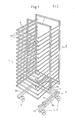
- Fig. 1 einen Stickenwagen eines Stickenwagenpaares in perspektivischer Ansicht,
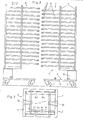
- Fig. 2 eine Seitenansicht der beiden Stickenwagen des Stickenwagenpaares vor dem Ineinanderschieben,
- Fig. 3 eine Draufsicht auf die ineinandergeschobenen Fahruntersätze, wobei die Traggestelle zur besseren Veranschaulichung nicht gezeichnet sind.
- Jeder der beiden Stickenwagen 1, 2 besitzt einen fahrbaren Untersatz 3 mit gummibereiften Lenkrollen 4 Das Traggestell 5 mit den horizontalen Backblechhalterungen ist mittels Schrauben auf dem Untersatz 3 befestigt. Las Traggestell 5 besteht aus zwei rechteckingen, hechgestellt Profilrahmen 7, an denen die als Winkelprofils chienen ausgebildeten Backblechhalterungen 6 angeschweisst sind.
- Die Backblechhalterungen 6 sind in gleichmässigen Abständen übereinander angeordnet und ragen (in Einschieberichtung des Stickennragens gesehen) freitragend nach vorne. Die vorderen Enden je zweier Winkelprofilschienen sind durch Flachstahl-Querstreben 13 miteinander verbunden.
- Wie aus der Fig. 2 ersichtlich ist, sind die Backblechhalterungen 6 der beiden Wagen 1, 2 des Wagenpaares in der Höhe versetzt zueinander angeordnet, so dass beim Ineinanderschieben die Backblechhalterungen des einen Wagens 1 in die Zwischenräume der Backblechhalterungen des anderen Wagens 2 zu liegen kommen.
- Die Fahruntersätze 3 sind ebenfalls aus Profilen aufgebaut. Jeder Untersatz 3 umfasst zwei frei nach vorne ragende, parallele Längsträger Sa - 8d, die hinten mittels zweier Querträger 9 miteinander versteift sind. Mittig zwischen den Querträgern 9 ist ein aus Eisenblech konstruierter Keil 10 an den ersteren befestigt. Das Traggestell 5 ist auf dem Keil 10 aufgeschraubt.
- Beim einen Wagen 1 ist neben dem Längsträger 8a eine Führungsschiene 11 montiert, deren vorderes Ende von diesem Längsträger 9 nach innen weggebogen ist. Dadurch entsteht zwischen der Führungsschiene 11 und ihrem benachbarten Längsträger 8a ein vorne erweiterter Führungskanal 12, in welchen der entsprechende, etwas nach innen versetzte Längsträger 8d des anderen Wagens 2 beim Ineinanderschieben eindringt.
- Der zweite Längsträger 8d des ersten Wagens ist ebenfalls etwas nach innen versetzt, wie der Längsträger 8c des zweiten Wagens 2. Dadurch wird erreicht, dass die beiden einander zugeordneten Längsträger 8a, 8c bzw. 8b, 8d beim Einschieben eng benachbart nebeneinander zu liegen kommen. Aus den Figuren ist ersichtlich, dass die beanspruchte Bodenfläche der beiden ineinandergeschobenen Wagen 1, 2 gleich gross ist wie die Bodenfläche jedes einzelnen Wagens.
- Bei der vorbeschriebenen und dargestellten Ausführungsform handelt es sich um Stickenwagen für einen Ofen, der ungefähr 30 cm ab Boden steht. Der Stichenwagen wird beim Backen unter die Ofenplatte gefahren, die an ihrer Vorderseite einen keilförmigen Ausschnitt aufweist zum ofnehmen des Keils 10 auf den Fahruntersatz. Der Stickenwagen könnte aber auch so ausgeführt werden, dass das Traggeste direkt auf den Profilträgern des Fahruntersatzes befestigt wäre; dies für Backöfen, bei denen mit dem gesanten Wagen in den Ofen eingefahren wird. In diesem Falle sind natürlich keine Gummiräder möglich wegen der hohen Backtemperaturen von ca. 250° - 270° C.
- Sinngemäss könnte die Führung durch an den Querträgern 9 angebrachte Zapfen und Führungsschienen erzielt werden. Ein Führung ist immer notwendig, damit die ausladenden Backblechhalterungen vor dem Einfahren in das durch den Profilrahmen 7 gebildete Joch geführt werden. Aus diesem Grunde ist es wichtig, dass die Führung im Wagen-Fahruntersatz nicht zuviel Spiel aufweist und ein einwandfreies Ausrichten der beiden Wagen ermöglicht. Andererseits können die Winkelprofile der Backblechhalterungen 6 durch Zwischenstücke im Abstand von den Profilrahmcn 7 distanziert werden, so dass das Spiel zwischen den Backblcchhalterungen und den Profilrahmen 7 etwas grösser ist als das Spiel im Führungskanal 12. Dadurch wird das Ineinanderschieben der beiden Wagen erleichtert. Die Profilrahmen 7 sind so nach hinten versetzt, dass beide Wagen ganz ineinandergeschoben werden können, so dass sie gemeinsam die gleiche Grundfläche beanspruchen wie ein einzelner Wagen.
- Statt im Fahruntersatz könnte die Führung auch im Oberteil des Wagens vorgesehen sein. Es wäre auch möglich, zwei Führungen vorzusehen, die eine im Untersatz, die andere im Oberteil.
Claims (10)
Priority Applications (1)
| Application Number | Priority Date | Filing Date | Title |
|---|---|---|---|
| AT79810114T ATE567T1 (de) | 1978-10-03 | 1979-10-03 | Stickenwagen fuer backbleche. |
Applications Claiming Priority (2)
| Application Number | Priority Date | Filing Date | Title |
|---|---|---|---|
| CH1026078 | 1978-10-03 | ||
| CH10260/78 | 1978-10-03 |
Publications (2)
| Publication Number | Publication Date |
|---|---|
| EP0010068A1 true EP0010068A1 (de) | 1980-04-16 |
| EP0010068B1 EP0010068B1 (de) | 1982-01-20 |
Family
ID=4361245
Family Applications (1)
| Application Number | Title | Priority Date | Filing Date |
|---|---|---|---|
| EP79810114A Expired EP0010068B1 (de) | 1978-10-03 | 1979-10-03 | Stickenwagen für Backbleche |
Country Status (3)
| Country | Link |
|---|---|
| EP (1) | EP0010068B1 (de) |
| AT (1) | ATE567T1 (de) |
| DE (1) | DE2961896D1 (de) |
Cited By (3)
| Publication number | Priority date | Publication date | Assignee | Title |
|---|---|---|---|---|
| AT391591B (de) * | 1989-06-30 | 1990-10-25 | Koenig Helmut | Vorrichtung zur aufeinanderfolgenden belegung mehrerer teigstuecktraeger eines backwagens mit teigstuecken |
| EP0442237A1 (de) * | 1990-02-16 | 1991-08-21 | Michelle Bayle | Servierwagen für Gemeinschaften |
| EP2048056A3 (de) * | 2007-10-08 | 2010-09-22 | Wanzl Metallwarenfabrik GmbH | Stapelbarer Transportwagen |
Citations (1)
| Publication number | Priority date | Publication date | Assignee | Title |
|---|---|---|---|---|
| GB1260035A (en) * | 1969-08-12 | 1972-01-12 | Michael John Huffey | Improvements in nesting trolleys |
-
1979
- 1979-10-03 EP EP79810114A patent/EP0010068B1/de not_active Expired
- 1979-10-03 AT AT79810114T patent/ATE567T1/de not_active IP Right Cessation
- 1979-10-03 DE DE7979810114T patent/DE2961896D1/de not_active Expired
Patent Citations (1)
| Publication number | Priority date | Publication date | Assignee | Title |
|---|---|---|---|---|
| GB1260035A (en) * | 1969-08-12 | 1972-01-12 | Michael John Huffey | Improvements in nesting trolleys |
Cited By (4)
| Publication number | Priority date | Publication date | Assignee | Title |
|---|---|---|---|---|
| AT391591B (de) * | 1989-06-30 | 1990-10-25 | Koenig Helmut | Vorrichtung zur aufeinanderfolgenden belegung mehrerer teigstuecktraeger eines backwagens mit teigstuecken |
| EP0442237A1 (de) * | 1990-02-16 | 1991-08-21 | Michelle Bayle | Servierwagen für Gemeinschaften |
| FR2658401A1 (fr) * | 1990-02-16 | 1991-08-23 | Saint Romain Daniel | Chariot de service pour collectivites. |
| EP2048056A3 (de) * | 2007-10-08 | 2010-09-22 | Wanzl Metallwarenfabrik GmbH | Stapelbarer Transportwagen |
Also Published As
| Publication number | Publication date |
|---|---|
| EP0010068B1 (de) | 1982-01-20 |
| ATE567T1 (de) | 1982-02-15 |
| DE2961896D1 (en) | 1982-03-04 |
Similar Documents
| Publication | Publication Date | Title |
|---|---|---|
| DE2927116C2 (de) | ||
| EP0010068B1 (de) | Stickenwagen für Backbleche | |
| AT228141B (de) | Vorrichtung zum Beschicken von Etagenbacköfen | |
| AT402194B (de) | Verfahren und anlage zum sortieren von zuschnitten | |
| DE2459479A1 (de) | Baeckereibetriebsverfahren | |
| DE20101501U1 (de) | Stikkenofen | |
| DE3604657A1 (de) | Vorrichtung zum geordneten stellen oder legen insbesondere von flachmaterial wie bretter od.dgl. | |
| DE1928652A1 (de) | Backofen | |
| EP2302313A1 (de) | Trocknerwagen | |
| DE2804545A1 (de) | Etagenbackofen | |
| DE19912303C1 (de) | Vorrichtung zur Übergabe von Gärgut, zum Beispiel Brötchen, von einem Kipptrögelapparat auf ein Backblech | |
| DE2059004A1 (de) | Einrichtung zum Beschicken von Mehretagenbackoefen | |
| DE2833226C2 (de) | Backschragen | |
| AT389983B (de) | Einschiesswagen | |
| DE7926755U1 (de) | Rahmen zur aufnahme keramischer formkoerper | |
| DE3225067A1 (de) | Vorrichtung und verfahren zum wenden von teigstuecken | |
| DE3326895A1 (de) | Stickenbackofen | |
| DE202006014575U1 (de) | Backofen als Wagenofen mit Steinplatten | |
| DE69306704T2 (de) | Lagereinrichtung mit fahrbaren Tragelementen | |
| DE10154086A1 (de) | Brennhilfsmittel zum Brennen von Dachziegeln | |
| DE2547249A1 (de) | Mobile baeckereianlage | |
| DE3330693A1 (de) | Backofen | |
| DE3400790A1 (de) | Verfahren und vorrichtung zum backen | |
| DE2807430B1 (de) | Backofen | |
| DE3903901A1 (de) | Verfahren und vorrichtung zum beschicken eines backwagens |
Legal Events
| Date | Code | Title | Description |
|---|---|---|---|
| PUAI | Public reference made under article 153(3) epc to a published international application that has entered the european phase |
Free format text: ORIGINAL CODE: 0009012 |
|
| AK | Designated contracting states |
Designated state(s): AT CH DE FR GB IT SE |
|
| 17P | Request for examination filed | ||
| ITF | It: translation for a ep patent filed | ||
| GRAA | (expected) grant |
Free format text: ORIGINAL CODE: 0009210 |
|
| AK | Designated contracting states |
Designated state(s): AT CH DE FR GB IT SE |
|
| REF | Corresponds to: |
Ref document number: 567 Country of ref document: AT Date of ref document: 19820215 Kind code of ref document: T |
|
| REF | Corresponds to: |
Ref document number: 2961896 Country of ref document: DE Date of ref document: 19820304 |
|
| PGFP | Annual fee paid to national office [announced via postgrant information from national office to epo] |
Ref country code: AT Payment date: 19830909 Year of fee payment: 5 |
|
| PGFP | Annual fee paid to national office [announced via postgrant information from national office to epo] |
Ref country code: FR Payment date: 19830912 Year of fee payment: 5 |
|
| PGFP | Annual fee paid to national office [announced via postgrant information from national office to epo] |
Ref country code: DE Payment date: 19831010 Year of fee payment: 5 |
|
| PGFP | Annual fee paid to national office [announced via postgrant information from national office to epo] |
Ref country code: CH Payment date: 19840927 Year of fee payment: 6 |
|
| PGFP | Annual fee paid to national office [announced via postgrant information from national office to epo] |
Ref country code: SE Payment date: 19840930 Year of fee payment: 6 |
|
| PG25 | Lapsed in a contracting state [announced via postgrant information from national office to epo] |
Ref country code: AT Effective date: 19841003 |
|
| GBPC | Gb: european patent ceased through non-payment of renewal fee | ||
| PG25 | Lapsed in a contracting state [announced via postgrant information from national office to epo] |
Ref country code: FR Free format text: LAPSE BECAUSE OF NON-PAYMENT OF DUE FEES Effective date: 19850628 |
|
| PG25 | Lapsed in a contracting state [announced via postgrant information from national office to epo] |
Ref country code: DE Effective date: 19850702 |
|
| REG | Reference to a national code |
Ref country code: FR Ref legal event code: ST |
|
| PG25 | Lapsed in a contracting state [announced via postgrant information from national office to epo] |
Ref country code: SE Effective date: 19851004 |
|
| PG25 | Lapsed in a contracting state [announced via postgrant information from national office to epo] |
Ref country code: CH Effective date: 19851031 |
|
| REG | Reference to a national code |
Ref country code: CH Ref legal event code: PL |
|
| PG25 | Lapsed in a contracting state [announced via postgrant information from national office to epo] |
Ref country code: GB Effective date: 19881118 |
|
| EUG | Se: european patent has lapsed |
Ref document number: 79810114.3 Effective date: 19860730 |
|
| PLBE | No opposition filed within time limit |
Free format text: ORIGINAL CODE: 0009261 |
|
| STAA | Information on the status of an ep patent application or granted ep patent |
Free format text: STATUS: NO OPPOSITION FILED WITHIN TIME LIMIT |