EP0010073B1 - Eine Befestigungsschelle für das Anbringen von Rohren und dergleichen auf Strukturen - Google Patents
Eine Befestigungsschelle für das Anbringen von Rohren und dergleichen auf Strukturen Download PDFInfo
- Publication number
- EP0010073B1 EP0010073B1 EP79850068A EP79850068A EP0010073B1 EP 0010073 B1 EP0010073 B1 EP 0010073B1 EP 79850068 A EP79850068 A EP 79850068A EP 79850068 A EP79850068 A EP 79850068A EP 0010073 B1 EP0010073 B1 EP 0010073B1
- Authority
- EP
- European Patent Office
- Prior art keywords
- mounting clip
- bore
- annular frame
- members
- detention
- Prior art date
- Legal status (The legal status is an assumption and is not a legal conclusion. Google has not performed a legal analysis and makes no representation as to the accuracy of the status listed.)
- Expired
Links
- 230000008878 coupling Effects 0.000 claims description 8
- 238000010168 coupling process Methods 0.000 claims description 8
- 238000005859 coupling reaction Methods 0.000 claims description 8
- 210000002105 tongue Anatomy 0.000 description 3
- 238000004519 manufacturing process Methods 0.000 description 2
- 229910000831 Steel Inorganic materials 0.000 description 1
- 238000004873 anchoring Methods 0.000 description 1
- 210000000080 chela (arthropods) Anatomy 0.000 description 1
- 230000014759 maintenance of location Effects 0.000 description 1
- 230000002787 reinforcement Effects 0.000 description 1
- 239000010959 steel Substances 0.000 description 1
Images
Classifications
-
- F—MECHANICAL ENGINEERING; LIGHTING; HEATING; WEAPONS; BLASTING
- F16—ENGINEERING ELEMENTS AND UNITS; GENERAL MEASURES FOR PRODUCING AND MAINTAINING EFFECTIVE FUNCTIONING OF MACHINES OR INSTALLATIONS; THERMAL INSULATION IN GENERAL
- F16L—PIPES; JOINTS OR FITTINGS FOR PIPES; SUPPORTS FOR PIPES, CABLES OR PROTECTIVE TUBING; MEANS FOR THERMAL INSULATION IN GENERAL
- F16L3/00—Supports for pipes, cables or protective tubing, e.g. hangers, holders, clamps, cleats, clips, brackets
- F16L3/08—Supports for pipes, cables or protective tubing, e.g. hangers, holders, clamps, cleats, clips, brackets substantially surrounding the pipe, cable or protective tubing
- F16L3/10—Supports for pipes, cables or protective tubing, e.g. hangers, holders, clamps, cleats, clips, brackets substantially surrounding the pipe, cable or protective tubing divided, i.e. with two members engaging the pipe, cable or protective tubing
- F16L3/1083—Supports for pipes, cables or protective tubing, e.g. hangers, holders, clamps, cleats, clips, brackets substantially surrounding the pipe, cable or protective tubing divided, i.e. with two members engaging the pipe, cable or protective tubing with two members, the two members being hooked in on one side and fastened together on the other side
-
- F—MECHANICAL ENGINEERING; LIGHTING; HEATING; WEAPONS; BLASTING
- F16—ENGINEERING ELEMENTS AND UNITS; GENERAL MEASURES FOR PRODUCING AND MAINTAINING EFFECTIVE FUNCTIONING OF MACHINES OR INSTALLATIONS; THERMAL INSULATION IN GENERAL
- F16L—PIPES; JOINTS OR FITTINGS FOR PIPES; SUPPORTS FOR PIPES, CABLES OR PROTECTIVE TUBING; MEANS FOR THERMAL INSULATION IN GENERAL
- F16L3/00—Supports for pipes, cables or protective tubing, e.g. hangers, holders, clamps, cleats, clips, brackets
- F16L3/24—Supports for pipes, cables or protective tubing, e.g. hangers, holders, clamps, cleats, clips, brackets with special member for attachment to profiled girders
Definitions
- the invention relates to a mounting clip for holding pipes and similar fittings to be fixed to structures of the kind referred to in the preamble of claim 1.
- US Patent Specification 3 301 514 discloses a clip comprising two wriggly strip members one end of which having a coupling element and the other end having an abutment intended to cooperate with a circular bore of a supporting plate.
- This clip requires two strip pieces of different configuration which are inconvenient and costly to manufacture.
- the abutment is intended to engage in a circular bore of a supporting plate.
- US Patent Specification 3 139 261 discloses a mounting clip comprising equally formed strip members, one end of which having securing or anchoring means, such as slots and the other end of which having coupling elements adapted to be locked with each other in use.
- Each coupling element comprises a detention bore of substantially triangular shape and an externally projecting locking lug located at the base of the detention bore.
- One object of the present invention is to obtain a mounting clip for convenient, smooth and rapid engaging operation of the clip with a supporting structure with an increased working efficiency.
- the mounting clip according to this invention can be used to conveniently fix a pipe or a conduit to a desired position on a steel beam or angle in a short time and with a simple operation.
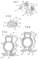
- the mounting clip 10 comprises two wriggly strip members 12, 12 and an associated linking loop 32.
- FIG. 1 the two wriggly strip members 12, 12 of substantially the same structure and configuration are shown which strip member includes an arm portion 14 having at its one end a base tongue 16 and at its opposite end a stem portion 18 contiguous with a coupling element 20.
- the coupling element 20 comprises a detention bore 22 of substantially trapezoidal form and a locking lug 24 projecting externally from the base of the trapezoidal detention bore 22 which includes a tip corner portion 26 for receiving the locking lug 24 of the other strip member when two strip members 12, 12 are interlocked with one another.
- the linking loop 32 for use with the strip members 12, 12 is shown comprising an annular frame 34, bridge members 36, 36 extending across the annular frame 34 and outwardly extending symmetrical protuberances 38, 38.
- the linking loop 32 is placed inside a base plate 44.
- Figure 4 is concerned with another embodiment of the invention in which the locking lugs 24, 24 project outwardly and the linking loop 32 is placed outside the base plate 44.
- the inwardly projecting locking lugs 24, 24 as shown in Figure 3 have the advantage that any risk of injuring the operator's hands or fingers or damaging other constructional objects such as pipes or wires may positively be avoided.
- the tongues 16, 16 of the strip members 12, 12 are previously associated with the linking loop 32 for convenient, smooth and rapid engaging operation of the mounting clip 10 with the base structure 44 with increased working efficiency particularly when the clip is fixed overhead.
- the clip 10 including two separate strips of the same configuration and structure is suitable for mass production and each strip can be associated with the linking loop 32 in both of its semi-circular spaces 40.
Landscapes
- Engineering & Computer Science (AREA)
- General Engineering & Computer Science (AREA)
- Mechanical Engineering (AREA)
- Supports For Pipes And Cables (AREA)
- Clamps And Clips (AREA)
Claims (2)
Applications Claiming Priority (2)
| Application Number | Priority Date | Filing Date | Title |
|---|---|---|---|
| JP11875878A JPS5547081A (en) | 1978-09-27 | 1978-09-27 | Fitting metal for pipe |
| JP118758/78 | 1978-09-27 |
Publications (2)
| Publication Number | Publication Date |
|---|---|
| EP0010073A1 EP0010073A1 (de) | 1980-04-16 |
| EP0010073B1 true EP0010073B1 (de) | 1982-10-27 |
Family
ID=14744321
Family Applications (1)
| Application Number | Title | Priority Date | Filing Date |
|---|---|---|---|
| EP79850068A Expired EP0010073B1 (de) | 1978-09-27 | 1979-07-12 | Eine Befestigungsschelle für das Anbringen von Rohren und dergleichen auf Strukturen |
Country Status (5)
| Country | Link |
|---|---|
| US (1) | US4327887A (de) |
| EP (1) | EP0010073B1 (de) |
| JP (1) | JPS5547081A (de) |
| DE (1) | DE2963933D1 (de) |
| ES (1) | ES483442A1 (de) |
Cited By (1)
| Publication number | Priority date | Publication date | Assignee | Title |
|---|---|---|---|---|
| PL126829U1 (pl) * | 2018-01-11 | 2019-07-15 | Palich Piotr Klimawent | Obejma zaciskowa typu clic |
Families Citing this family (26)
| Publication number | Priority date | Publication date | Assignee | Title |
|---|---|---|---|---|
| US5108055A (en) * | 1991-09-04 | 1992-04-28 | Amp Incorporated | Conduit holder |
| US5580102A (en) * | 1991-11-27 | 1996-12-03 | The Dow Chemical Company | Pipe support and pipeline therewith |
| DE4208791A1 (de) * | 1992-03-19 | 1993-09-23 | Kabelmetal Electro Gmbh | Vorrichtung zur befestigung eines strangfoermigen gegenstandes an einer unterlage |
| US5380156A (en) * | 1993-04-12 | 1995-01-10 | Iacovino; Robert | Ceiling fan balance apparatus |
| US5524667A (en) * | 1995-07-12 | 1996-06-11 | Consistent Textile Industry, Inc. | Spout master |
| DE29801108U1 (de) * | 1998-01-23 | 1998-03-05 | Alcatel Alsthom Compagnie Générale d'Electricité, Paris | Vorrichtung zur Befestigung von strangförmigen Gegenständen |
| US6042067A (en) * | 1999-01-25 | 2000-03-28 | Mendelsohn; Fred M. | Clamping holder for a lamp for a flowerpot |
| DE19961004C2 (de) * | 1999-12-17 | 2002-03-14 | Paul Stange | Rohrhalterung |
| US6454311B1 (en) | 2000-09-28 | 2002-09-24 | Lincoln Brass Works, Inc. | Gas line mounting assembly |
| US6729587B1 (en) * | 2002-05-31 | 2004-05-04 | Bellsouth Intellectual Property Corporation | Communication cable support for drop ceiling |
| US7017947B1 (en) * | 2003-10-28 | 2006-03-28 | Bellsouth Intellectual Property Corporation | Pipe holder |
| ZA200406121B (en) * | 2003-11-28 | 2005-08-31 | Pratley Invest (Proprietary) Ltd | Device for fastening a cable or a conduit |
| GB2429236A (en) * | 2005-08-20 | 2007-02-21 | Leawood Mfg Ltd | A handle signage mounting clip |
| US7942242B1 (en) * | 2007-05-14 | 2011-05-17 | O'connor Daniel J | Urban emergency escape method and system |
| US8025508B2 (en) * | 2009-12-23 | 2011-09-27 | Hubbell Incorporated | Solar panel grounding connector |
| USD745846S1 (en) * | 2012-03-01 | 2015-12-22 | Ilsco Corporation | Solar panel electrical connector |
| US8602829B2 (en) * | 2012-03-23 | 2013-12-10 | Schneider Electric USA, Inc. | Cable connector with integrated shoe |
| US20150190704A1 (en) * | 2014-01-09 | 2015-07-09 | Patrick McDowell | Mounting bracket and brake assembly |
| NL2015404B1 (en) * | 2015-09-07 | 2017-03-22 | Walraven Holding Bv J Van | Conduit clip. |
| NL2015917B1 (en) * | 2015-12-07 | 2017-06-28 | Walraven Holding Bv J Van | Pipe clamp for a range of pipe diameters. |
| US10637164B2 (en) | 2017-03-16 | 2020-04-28 | Hubbell Incorporated | Bonding connectors |
| JP6544754B1 (ja) * | 2018-05-07 | 2019-07-17 | 晃輝 平山 | 係止具及び係止方法 |
| JP7078258B2 (ja) * | 2018-08-27 | 2022-05-31 | 株式会社国元商会 | 配管などの取付け金具 |
| DE102019202306B4 (de) * | 2019-02-20 | 2024-07-04 | Thyssenkrupp Ag | Stabilisatorschelle, Stabilisator-Stabilisatorschellen-Anordnung und Verfahren zum Herstellen einer Stabilisatorschelle |
| US10907750B2 (en) | 2019-04-29 | 2021-02-02 | Aptiv Technologies Limited | Modular retainer assembly |
| US12287053B2 (en) * | 2022-02-14 | 2025-04-29 | Tyco Fire & Security Gmbh | Conduit support assembly for HVAC and R system |
Family Cites Families (11)
| Publication number | Priority date | Publication date | Assignee | Title |
|---|---|---|---|---|
| US397036A (en) * | 1889-01-29 | Conductor-support | ||
| DE1251093B (de) * | 1967-09-28 | |||
| US1786612A (en) * | 1930-04-08 | 1930-12-30 | Arthur P Heslop | Garden-hose clamp |
| US1860861A (en) * | 1931-09-14 | 1932-05-31 | United Carr Fastener Corp | Snap fastener secured conduit-holding member |
| US2318816A (en) * | 1942-06-27 | 1943-05-11 | Tinnerman Products Inc | Fastening device |
| US3139261A (en) * | 1960-01-27 | 1964-06-30 | George A Tinnerman | Mounting clips or clamps |
| US3185419A (en) * | 1963-02-25 | 1965-05-25 | Orian C Kindorf | Pipe hanger |
| US3301514A (en) * | 1964-09-30 | 1967-01-31 | Sugaya Masao | Clips for conduits or pipes |
| JPS4332042Y1 (de) * | 1964-10-14 | 1968-12-26 | ||
| US3515363A (en) * | 1968-05-06 | 1970-06-02 | Illinois Tool Works | Spring clip |
| US4157800A (en) * | 1976-08-06 | 1979-06-12 | Millard Andrich | Pipe clamp |
-
1978
- 1978-09-27 JP JP11875878A patent/JPS5547081A/ja active Pending
-
1979
- 1979-06-27 US US06/052,574 patent/US4327887A/en not_active Expired - Lifetime
- 1979-07-12 DE DE7979850068T patent/DE2963933D1/de not_active Expired
- 1979-07-12 EP EP79850068A patent/EP0010073B1/de not_active Expired
- 1979-08-17 ES ES483442A patent/ES483442A1/es not_active Expired
Cited By (1)
| Publication number | Priority date | Publication date | Assignee | Title |
|---|---|---|---|---|
| PL126829U1 (pl) * | 2018-01-11 | 2019-07-15 | Palich Piotr Klimawent | Obejma zaciskowa typu clic |
Also Published As
| Publication number | Publication date |
|---|---|
| ES483442A1 (es) | 1980-03-01 |
| EP0010073A1 (de) | 1980-04-16 |
| US4327887A (en) | 1982-05-04 |
| DE2963933D1 (en) | 1982-12-02 |
| JPS5547081A (en) | 1980-04-02 |
Similar Documents
| Publication | Publication Date | Title |
|---|---|---|
| EP0010073B1 (de) | Eine Befestigungsschelle für das Anbringen von Rohren und dergleichen auf Strukturen | |
| US4958792A (en) | Clip for supporting conduit and the like | |
| US4610562A (en) | Perimeter clip | |
| US3536281A (en) | Bracket structure | |
| US5533696A (en) | Conduit clip | |
| US5020272A (en) | Landscape edging system | |
| CA2084559C (en) | Pipe hanging clamp adapted for soldering | |
| US4742600A (en) | Band clamp | |
| US5819376A (en) | Hose clamp | |
| JP3137110B2 (ja) | 成形されたクリップ | |
| JP3071444B2 (ja) | 配管・配線把持用固定クランプ | |
| US5172879A (en) | Attachment clamp | |
| US5377940A (en) | Self-restraining loop clamp | |
| US20170163017A1 (en) | Masonry box positioning support | |
| PL160200B1 (pl) | Obejma zaciskowa PL PL PL | |
| US3995725A (en) | Hanger for conductor rails | |
| US4225103A (en) | Pipe clamp device | |
| JP2585357Y2 (ja) | ホースクリップ | |
| US5036567A (en) | Push-in fastener clip | |
| JP3843137B2 (ja) | ホースクリップとそれのための固定用部材 | |
| US4305182A (en) | Spring retainer strip for attaching a liner and gasket to a refrigerator door | |
| US5940939A (en) | One-piece flat band clamp | |
| EP0337594B1 (de) | Sich selbst ausrichtende Federklemme | |
| JP2591296Y2 (ja) | ホースクリップ | |
| JP2004150512A (ja) | ホースクランプ |
Legal Events
| Date | Code | Title | Description |
|---|---|---|---|
| PUAI | Public reference made under article 153(3) epc to a published international application that has entered the european phase |
Free format text: ORIGINAL CODE: 0009012 |
|
| AK | Designated contracting states |
Designated state(s): BE CH DE FR GB IT NL SE |
|
| ITCL | It: translation for ep claims filed |
Representative=s name: BARZANO' E ZANARDO ROMA S.P.A. |
|
| DET | De: translation of patent claims | ||
| 17P | Request for examination filed | ||
| ITF | It: translation for a ep patent filed | ||
| GRAA | (expected) grant |
Free format text: ORIGINAL CODE: 0009210 |
|
| AK | Designated contracting states |
Designated state(s): BE CH DE FR GB IT NL SE |
|
| REF | Corresponds to: |
Ref document number: 2963933 Country of ref document: DE Date of ref document: 19821202 |
|
| ET | Fr: translation filed | ||
| ITTA | It: last paid annual fee | ||
| PGFP | Annual fee paid to national office [announced via postgrant information from national office to epo] |
Ref country code: BE Payment date: 19920710 Year of fee payment: 14 |
|
| PGFP | Annual fee paid to national office [announced via postgrant information from national office to epo] |
Ref country code: SE Payment date: 19920724 Year of fee payment: 14 |
|
| PGFP | Annual fee paid to national office [announced via postgrant information from national office to epo] |
Ref country code: NL Payment date: 19920731 Year of fee payment: 14 |
|
| PGFP | Annual fee paid to national office [announced via postgrant information from national office to epo] |
Ref country code: CH Payment date: 19921023 Year of fee payment: 14 |
|
| PGFP | Annual fee paid to national office [announced via postgrant information from national office to epo] |
Ref country code: FR Payment date: 19930630 Year of fee payment: 15 |
|
| PGFP | Annual fee paid to national office [announced via postgrant information from national office to epo] |
Ref country code: GB Payment date: 19930712 Year of fee payment: 15 |
|
| PG25 | Lapsed in a contracting state [announced via postgrant information from national office to epo] |
Ref country code: SE Effective date: 19930713 |
|
| PG25 | Lapsed in a contracting state [announced via postgrant information from national office to epo] |
Ref country code: CH Effective date: 19930731 Ref country code: BE Effective date: 19930731 |
|
| PGFP | Annual fee paid to national office [announced via postgrant information from national office to epo] |
Ref country code: DE Payment date: 19930809 Year of fee payment: 15 |
|
| BERE | Be: lapsed |
Owner name: NEGUROSU ELECTRICAL INDUSTRIES CO. LTD Effective date: 19930731 |
|
| PG25 | Lapsed in a contracting state [announced via postgrant information from national office to epo] |
Ref country code: NL Effective date: 19940201 |
|
| NLV4 | Nl: lapsed or anulled due to non-payment of the annual fee | ||
| REG | Reference to a national code |
Ref country code: CH Ref legal event code: PL |
|
| PG25 | Lapsed in a contracting state [announced via postgrant information from national office to epo] |
Ref country code: GB Effective date: 19940712 |
|
| EUG | Se: european patent has lapsed |
Ref document number: 79850068.2 Effective date: 19940210 |
|
| GBPC | Gb: european patent ceased through non-payment of renewal fee |
Effective date: 19940712 |
|
| PG25 | Lapsed in a contracting state [announced via postgrant information from national office to epo] |
Ref country code: FR Effective date: 19950331 |
|
| PG25 | Lapsed in a contracting state [announced via postgrant information from national office to epo] |
Ref country code: DE Effective date: 19950401 |
|
| REG | Reference to a national code |
Ref country code: FR Ref legal event code: ST |
|
| PLBE | No opposition filed within time limit |
Free format text: ORIGINAL CODE: 0009261 |
|
| STAA | Information on the status of an ep patent application or granted ep patent |
Free format text: STATUS: NO OPPOSITION FILED WITHIN TIME LIMIT |