EP0010082A1 - Dispositif pour boucher le trou de coulée d'un récipient métallurgique - Google Patents
Dispositif pour boucher le trou de coulée d'un récipient métallurgique Download PDFInfo
- Publication number
- EP0010082A1 EP0010082A1 EP79890038A EP79890038A EP0010082A1 EP 0010082 A1 EP0010082 A1 EP 0010082A1 EP 79890038 A EP79890038 A EP 79890038A EP 79890038 A EP79890038 A EP 79890038A EP 0010082 A1 EP0010082 A1 EP 0010082A1
- Authority
- EP
- European Patent Office
- Prior art keywords
- closure body
- tap hole
- diameter
- gas line
- slag
- Prior art date
- Legal status (The legal status is an assumption and is not a legal conclusion. Google has not performed a legal analysis and makes no representation as to the accuracy of the status listed.)
- Granted
Links
Images

Classifications
-
- C—CHEMISTRY; METALLURGY
- C21—METALLURGY OF IRON
- C21C—PROCESSING OF PIG-IRON, e.g. REFINING, MANUFACTURE OF WROUGHT-IRON OR STEEL; TREATMENT IN MOLTEN STATE OF FERROUS ALLOYS
- C21C5/00—Manufacture of carbon-steel, e.g. plain mild steel, medium carbon steel or cast steel or stainless steel
- C21C5/28—Manufacture of steel in the converter
- C21C5/42—Constructional features of converters
- C21C5/46—Details or accessories
- C21C5/4653—Tapholes; Opening or plugging thereof
-
- B—PERFORMING OPERATIONS; TRANSPORTING
- B22—CASTING; POWDER METALLURGY
- B22D—CASTING OF METALS; CASTING OF OTHER SUBSTANCES BY THE SAME PROCESSES OR DEVICES
- B22D2/00—Arrangement of indicating or measuring devices, e.g. for temperature or viscosity of the fused mass
- B22D2/001—Arrangement of indicating or measuring devices, e.g. for temperature or viscosity of the fused mass for the slag appearance in a molten metal stream
-
- B—PERFORMING OPERATIONS; TRANSPORTING
- B22—CASTING; POWDER METALLURGY
- B22D—CASTING OF METALS; CASTING OF OTHER SUBSTANCES BY THE SAME PROCESSES OR DEVICES
- B22D41/00—Casting melt-holding vessels, e.g. ladles, tundishes, cups or the like
- B22D41/14—Closures
-
- F—MECHANICAL ENGINEERING; LIGHTING; HEATING; WEAPONS; BLASTING
- F27—FURNACES; KILNS; OVENS; RETORTS
- F27D—DETAILS OR ACCESSORIES OF FURNACES, KILNS, OVENS OR RETORTS, IN SO FAR AS THEY ARE OF KINDS OCCURRING IN MORE THAN ONE KIND OF FURNACE
- F27D3/00—Charging; Discharging; Manipulation of charge
- F27D3/15—Tapping equipment; Equipment for removing or retaining slag
- F27D3/1509—Tapping equipment
- F27D3/1536—Devices for plugging tap holes, e.g. plugs stoppers
Definitions
- a device for closing the tap hole of a metallurgical vessel in which an insertable into the tap hole, with respect to the tap hole wall leaving an annular gap and containing a compressed gas line, is provided, which has a tapering opening for the compressed gas line Has outer jacket.
- Such a device is used to make a separation of metal and slag when tapping, the known device is particularly easy to use and can be used repeatedly, u. even if the lining of the tap hole is already subject to wear.
- the closure body is designed as a truncated cone, on the mouth side of which a cylindrical extension is provided. This device has been in use in small converters for a long time. Difficulties arose when an attempt was made to use this device for large converters as well, with rapid wear and tear caused by the much higher heat exposure of a large converter.
- the invention aims to improve the known device, u. in the respect that an application also with Large converters with a long shelf life are guaranteed, with a better slag retention effect - corresponding to the higher slag bath height of a large converter - to be achieved.
- the manufacturing costs of the closure body, which is a wearing part, should also be kept as low as possible.
- the outer jacket of the closure body is formed by a spherical cap-shaped surface which merges into a frustoconical surface, the height of the truncated cone being at least 1 times and at most 2.5 times the diameter of the mouth side
- the outlet opening of the compressed gas line is and. opening angle of the truncated cone is at least 15 and at most 70 0 .
- a particularly high durability results when the closure body consists of gray cast iron.
- Fig. 1 shows a schematically illustrated section through the converter during the casting of a molten steel.
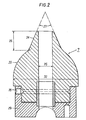
- Fig. 2 shows a section through the closure body along its axis on an enlarged scale.
- molten steel 2 In the converter vessel designated 1 there is the molten steel 2 with the slag layer 3 floating thereon.
- the steel flows through the tap hole 4 into the ladle 5 located below.
- a closure body 7 fastened to a swivel arm 6 serves to close the pressurized gas line 8 is connected.
- the swivel arm 6 is articulated on the outer jacket 9 of the fresh vessel 1 and is connected by means of a pressure medium cylinder 10 with a toothed rack which can be actuated in both directions and which is attached to the outer jacket of the vessel
- the tap hole is closed as follows: as soon as the steel has flowed into the ladle 5, the slag 3 flows out through the tap hole 4.
- the solenoid valve 21 is opened, whereby the pressure medium cylinder 10 brings the swivel arm 6 into the closed position shown in dashed lines in FIG. 1.
- the solenoid valve 22 of the supply line of the closure body is actuated, whereby the closure body, which in the pivoted-back position shown in FIG. 1 is subjected to a partial pressure of the compressed gas for the purpose of cooling, is subjected to the full pressure of the compressed gas.
- the outflowing compressed gas causes air to be drawn in through the annular gap 13, indicated by arrows, according to the injector principle.
- the slag is pushed back into the fresh container by the compressed gas air flow and can then be poured into its own slag container.
- the compressed gas can e.g. Compressed air, argon or nitrogen can be used.
- the closure body 7 which is made of gray cast iron, has an outer jacket which is formed by a spherical (spherical) surface 23 which merges into a frustoconical surface 24 on the mouth side.
- the height 25 of the frustoconical surface is approximately 1.4 times the diameter 26 of the outlet-side outlet opening of the compressed gas line, and the opening angle 27 of the truncated cone is approximately 47 °.
- the diameter 26 is approximately one third of the diameter 31 of the tap hole 4; the spherical surface 23 of the closure body 7 has a diameter 32 which is approximately 1.5 times the tap hole diameter 31.
- closure body 7 Due to the specially designed shape of the closure body 7, a particularly high durability is achieved even with the highest heat load. Furthermore, this form improves the slag retention effect, ie only less compressed air is required to retain the slag with the closure body according to the invention.
- the closure body is also inexpensive to manufacture, as long as it is manufactured using the gray cast iron process, and post-processing can be dispensed with.
- a directional joint 30 is used to precisely adjust the closure body 7 relative to the tap hole 4.
- the pressure medium cylinder To protect the pressure medium cylinder, it is installed in a heat protection box 33 which is provided with an air shower (not shown) for cooling.
- the compressed air lines are expediently supplied via the support pins (not shown) of the converter vessel.
Landscapes
- Engineering & Computer Science (AREA)
- Mechanical Engineering (AREA)
- Chemical & Material Sciences (AREA)
- Manufacturing & Machinery (AREA)
- Materials Engineering (AREA)
- Metallurgy (AREA)
- Organic Chemistry (AREA)
- General Engineering & Computer Science (AREA)
- Furnace Charging Or Discharging (AREA)
- Carbon Steel Or Casting Steel Manufacturing (AREA)
- Waste-Gas Treatment And Other Accessory Devices For Furnaces (AREA)
Applications Claiming Priority (2)
| Application Number | Priority Date | Filing Date | Title |
|---|---|---|---|
| AT7147/78 | 1978-10-04 | ||
| AT714778A AT357183B (de) | 1978-10-04 | 1978-10-04 | Einrichtung zum verschliessen des stichloches eines metallurgischen gefaesses |
Publications (2)
| Publication Number | Publication Date |
|---|---|
| EP0010082A1 true EP0010082A1 (fr) | 1980-04-16 |
| EP0010082B1 EP0010082B1 (fr) | 1981-10-21 |
Family
ID=3593152
Family Applications (1)
| Application Number | Title | Priority Date | Filing Date |
|---|---|---|---|
| EP79890038A Expired EP0010082B1 (fr) | 1978-10-04 | 1979-10-01 | Dispositif pour boucher le trou de coulée d'un récipient métallurgique |
Country Status (7)
| Country | Link |
|---|---|
| US (1) | US4232855A (fr) |
| EP (1) | EP0010082B1 (fr) |
| JP (1) | JPS6032685B2 (fr) |
| AT (1) | AT357183B (fr) |
| CA (1) | CA1113716A (fr) |
| DE (1) | DE2961076D1 (fr) |
| SU (1) | SU965361A3 (fr) |
Cited By (2)
| Publication number | Priority date | Publication date | Assignee | Title |
|---|---|---|---|---|
| EP0173669A3 (fr) * | 1984-06-01 | 1987-04-29 | VOEST-ALPINE Aktiengesellschaft | Récipient métallurgique basculant |
| US5105873A (en) * | 1991-09-06 | 1992-04-21 | Warmington C Edward | Casting operation emergency shut-off apparatus |
Families Citing this family (9)
| Publication number | Priority date | Publication date | Assignee | Title |
|---|---|---|---|---|
| DE2921742C2 (de) * | 1979-05-29 | 1983-09-29 | Mannesmann AG, 4000 Düsseldorf | Elektro-Metallschmelzofen mit im Boden angeordneter Abstichöffnung |
| US4679773A (en) * | 1985-09-30 | 1987-07-14 | Wunsche Edgar R | Horizontal tapping furnace and method of operation |
| AT407399B (de) * | 1999-05-21 | 2001-02-26 | Voest Alpine Ind Anlagen | Verfahren zum verschliessen und öffnen eines stichloches eines metallurgischen gefässes |
| AT408965B (de) * | 2000-01-27 | 2002-04-25 | Voest Alpine Ind Anlagen | Einrichtung zum verschliessen eines abstichloches eines metallurgischen gefässes |
| CN1323146C (zh) * | 2005-06-24 | 2007-06-27 | 西北工业大学 | 一种三氧化二硼-碳化硅自润滑涂层的制备方法 |
| CH699511A2 (de) * | 2008-09-05 | 2010-03-15 | Stopinc Ag | Kupfer-Anodenofen mit Schiebeverschluss. |
| US8715567B2 (en) * | 2010-09-23 | 2014-05-06 | Gillespie + Powers, Inc. | Furnace tap hole flow control and tapper system and method of using the same |
| DE102018216285A1 (de) * | 2018-09-25 | 2020-03-26 | Sms Group Gmbh | Schlackenstopper |
| CN115090841B (zh) * | 2022-08-24 | 2022-11-15 | 北京科技大学 | 一种研究覆盖剂在中间包运动行为的装置及使用方法 |
Citations (3)
| Publication number | Priority date | Publication date | Assignee | Title |
|---|---|---|---|---|
| LU61204A1 (fr) * | 1970-06-26 | 1972-03-24 | ||
| US3973761A (en) * | 1973-09-27 | 1976-08-10 | Noranda Mines Limited | Furnace tapping apparatus |
| DE2639712A1 (de) * | 1975-12-17 | 1977-06-30 | Voest Ag | Verfahren und einrichtung zum verschliessen des stichloches eines metallurgischen gefaesses |
Family Cites Families (1)
| Publication number | Priority date | Publication date | Assignee | Title |
|---|---|---|---|---|
| US4007035A (en) * | 1973-05-31 | 1977-02-08 | United States Steel Corporation | Method of using an expendable tap hole tuyere in open hearth decarburization |
-
1978
- 1978-10-04 AT AT714778A patent/AT357183B/de not_active IP Right Cessation
-
1979
- 1979-09-06 CA CA335,140A patent/CA1113716A/fr not_active Expired
- 1979-09-12 US US06/074,882 patent/US4232855A/en not_active Expired - Lifetime
- 1979-10-01 JP JP54127243A patent/JPS6032685B2/ja not_active Expired
- 1979-10-01 EP EP79890038A patent/EP0010082B1/fr not_active Expired
- 1979-10-01 SU SU792823407A patent/SU965361A3/ru active
- 1979-10-01 DE DE7979890038T patent/DE2961076D1/de not_active Expired
Patent Citations (3)
| Publication number | Priority date | Publication date | Assignee | Title |
|---|---|---|---|---|
| LU61204A1 (fr) * | 1970-06-26 | 1972-03-24 | ||
| US3973761A (en) * | 1973-09-27 | 1976-08-10 | Noranda Mines Limited | Furnace tapping apparatus |
| DE2639712A1 (de) * | 1975-12-17 | 1977-06-30 | Voest Ag | Verfahren und einrichtung zum verschliessen des stichloches eines metallurgischen gefaesses |
Cited By (2)
| Publication number | Priority date | Publication date | Assignee | Title |
|---|---|---|---|---|
| EP0173669A3 (fr) * | 1984-06-01 | 1987-04-29 | VOEST-ALPINE Aktiengesellschaft | Récipient métallurgique basculant |
| US5105873A (en) * | 1991-09-06 | 1992-04-21 | Warmington C Edward | Casting operation emergency shut-off apparatus |
Also Published As
| Publication number | Publication date |
|---|---|
| AT357183B (de) | 1980-06-25 |
| JPS5550417A (en) | 1980-04-12 |
| DE2961076D1 (en) | 1981-12-24 |
| ATA714778A (de) | 1979-07-15 |
| CA1113716A (fr) | 1981-12-08 |
| US4232855A (en) | 1980-11-11 |
| SU965361A3 (ru) | 1982-10-07 |
| EP0010082B1 (fr) | 1981-10-21 |
| JPS6032685B2 (ja) | 1985-07-30 |
Similar Documents
| Publication | Publication Date | Title |
|---|---|---|
| DE2639712C2 (de) | Verfahren und Einrichtung zum Verschließen des Stichloches eines metallurgischen Gefäßes | |
| EP0010082B1 (fr) | Dispositif pour boucher le trou de coulée d'un récipient métallurgique | |
| DE1300209B (de) | Ausgussvorrichtung | |
| DE2709727C3 (de) | Einrichtung zum Auswechseln von Gießrohren an Gießgefäßen beim Stranggießen | |
| DE2919880C2 (de) | Feuerfestes Gießrohr zwischen Gießpfanne und Zwischenbehältern von Stranggießanlagen | |
| DE1951447C3 (de) | Ausflußschieberverschluß für Gefäße zum Vergießen von Metallen | |
| DE1938117B2 (de) | Behaelter mit schiebeverschluss fuer fluessige schmelze | |
| DE3000730C2 (de) | Vorrichtung zum Abtrennen von Schlacke von einer Schmelze | |
| DE69120071T2 (de) | Mehrstufiger eintauchausguss zum stranggiessen | |
| EP0010535B1 (fr) | Dispositif de fermeture du trou de coulée d'un récipient métallurgique | |
| DE19856343B4 (de) | Verfahren und Vorrichtung zur Früherkennung von Schlackendurchfluss im Schattenrohr einer Gießpfanne | |
| DE2318817A1 (de) | Vorrichtung zum giessen von geschmolzenem metall und arbeitsverfahren zur betaetigung der vorrichtung | |
| DE1949995A1 (de) | Zwischenbehaelter (Tundish) fuer Stranggiessanlagen | |
| DE1483645C3 (de) | Vorrichtung zur Herstellung von Gußblocken und Verfahren zum Betneb derselben | |
| DE2361344A1 (de) | Verfahren und vorrichtung zum eingiessen von metall in eine stranggiesskokille | |
| DE3878507T2 (de) | Gefaess und verfahren zum behandeln von metallschmelzen. | |
| EP1054067B1 (fr) | Procédé et dispositif pour obturer et ouvrir un trou de coulée dans un récipient métallurgique basculant | |
| EP0529108B1 (fr) | Busette à tiroir pour récipients métallurgiques | |
| DE2008805A1 (de) | Niederdruck-Spritzvorrichtung | |
| DE3046967C2 (de) | Vorrichtung zum Öffnen bzw. Schließen des Abstichloches eines Siemens-Martin-Ofens | |
| DE69300761T2 (de) | Innerer Ausguss aus feuerfestem Material zur Verwendung in metallurgischen Gefässen. | |
| DE8805975U1 (de) | Verschlußvorrichtung für das Abstichloch eines kippbaren Abstichkonverters | |
| EP1054068B1 (fr) | Procédé et dispositif pour obturer et ouvrir un trou de coulée dans un récipient métallurqique basculant | |
| DE2417490C3 (de) | Feuerfestes, aus Boden- und Schieberplatte bestehendes Plattenpaar für Schieberverschlüsse | |
| WO2000055380A1 (fr) | Procede et dispositif de coulee d'un metal en fusion |
Legal Events
| Date | Code | Title | Description |
|---|---|---|---|
| PUAI | Public reference made under article 153(3) epc to a published international application that has entered the european phase |
Free format text: ORIGINAL CODE: 0009012 |
|
| AK | Designated contracting states |
Designated state(s): DE FR GB IT LU SE |
|
| 17P | Request for examination filed | ||
| ITF | It: translation for a ep patent filed | ||
| GRAA | (expected) grant |
Free format text: ORIGINAL CODE: 0009210 |
|
| AK | Designated contracting states |
Designated state(s): DE FR GB IT LU SE |
|
| REF | Corresponds to: |
Ref document number: 2961076 Country of ref document: DE Date of ref document: 19811224 |
|
| PG25 | Lapsed in a contracting state [announced via postgrant information from national office to epo] |
Ref country code: LU Free format text: LAPSE BECAUSE OF NON-PAYMENT OF DUE FEES Effective date: 19821031 |
|
| PGFP | Annual fee paid to national office [announced via postgrant information from national office to epo] |
Ref country code: FR Payment date: 19890914 Year of fee payment: 11 |
|
| PGFP | Annual fee paid to national office [announced via postgrant information from national office to epo] |
Ref country code: SE Payment date: 19890918 Year of fee payment: 11 Ref country code: DE Payment date: 19890918 Year of fee payment: 11 |
|
| PGFP | Annual fee paid to national office [announced via postgrant information from national office to epo] |
Ref country code: LU Payment date: 19890920 Year of fee payment: 11 |
|
| PGFP | Annual fee paid to national office [announced via postgrant information from national office to epo] |
Ref country code: GB Payment date: 19890930 Year of fee payment: 11 |
|
| ITTA | It: last paid annual fee | ||
| PG25 | Lapsed in a contracting state [announced via postgrant information from national office to epo] |
Ref country code: GB Effective date: 19901001 |
|
| PG25 | Lapsed in a contracting state [announced via postgrant information from national office to epo] |
Ref country code: SE Effective date: 19901002 |
|
| GBPC | Gb: european patent ceased through non-payment of renewal fee | ||
| PG25 | Lapsed in a contracting state [announced via postgrant information from national office to epo] |
Ref country code: FR Effective date: 19910628 |
|
| PG25 | Lapsed in a contracting state [announced via postgrant information from national office to epo] |
Ref country code: DE Effective date: 19910702 |
|
| REG | Reference to a national code |
Ref country code: FR Ref legal event code: ST |
|
| EUG | Se: european patent has lapsed |
Ref document number: 79890038.7 Effective date: 19910603 |
|
| PLBE | No opposition filed within time limit |
Free format text: ORIGINAL CODE: 0009261 |
|
| STAA | Information on the status of an ep patent application or granted ep patent |
Free format text: STATUS: NO OPPOSITION FILED WITHIN TIME LIMIT |