EP0010086B1 - Bauelement für gebäude - Google Patents
Bauelement für gebäude Download PDFInfo
- Publication number
- EP0010086B1 EP0010086B1 EP78900051A EP78900051A EP0010086B1 EP 0010086 B1 EP0010086 B1 EP 0010086B1 EP 78900051 A EP78900051 A EP 78900051A EP 78900051 A EP78900051 A EP 78900051A EP 0010086 B1 EP0010086 B1 EP 0010086B1
- Authority
- EP
- European Patent Office
- Prior art keywords
- rail
- web portion
- clamping
- leg portions
- constructional
- Prior art date
- Legal status (The legal status is an assumption and is not a legal conclusion. Google has not performed a legal analysis and makes no representation as to the accuracy of the status listed.)
- Expired
Links
- 238000009434 installation Methods 0.000 claims abstract description 18
- 239000011521 glass Substances 0.000 claims description 12
- 239000004033 plastic Substances 0.000 claims description 3
- 229920003023 plastic Polymers 0.000 claims description 3
- 239000004411 aluminium Substances 0.000 claims description 2
- 229910052782 aluminium Inorganic materials 0.000 claims description 2
- XAGFODPZIPBFFR-UHFFFAOYSA-N aluminium Chemical compound [Al] XAGFODPZIPBFFR-UHFFFAOYSA-N 0.000 claims description 2
- 239000012858 resilient material Substances 0.000 claims description 2
- 238000005192 partition Methods 0.000 abstract description 10
- 239000000463 material Substances 0.000 abstract description 4
- 230000004075 alteration Effects 0.000 abstract 1
- 238000004873 anchoring Methods 0.000 description 8
- 238000009413 insulation Methods 0.000 description 4
- 238000005034 decoration Methods 0.000 description 3
- 238000007789 sealing Methods 0.000 description 3
- 238000005516 engineering process Methods 0.000 description 2
- 238000004519 manufacturing process Methods 0.000 description 2
- 229910052751 metal Inorganic materials 0.000 description 2
- 239000002184 metal Substances 0.000 description 2
- 229910000831 Steel Inorganic materials 0.000 description 1
- 238000007792 addition Methods 0.000 description 1
- 239000000969 carrier Substances 0.000 description 1
- 239000003086 colorant Substances 0.000 description 1
- 238000010276 construction Methods 0.000 description 1
- 238000005553 drilling Methods 0.000 description 1
- 230000000694 effects Effects 0.000 description 1
- 238000010616 electrical installation Methods 0.000 description 1
- 239000002657 fibrous material Substances 0.000 description 1
- 239000000945 filler Substances 0.000 description 1
- 239000006260 foam Substances 0.000 description 1
- 239000006261 foam material Substances 0.000 description 1
- 239000003365 glass fiber Substances 0.000 description 1
- 239000011490 mineral wool Substances 0.000 description 1
- 230000008707 rearrangement Effects 0.000 description 1
- 239000003566 sealing material Substances 0.000 description 1
- 239000010959 steel Substances 0.000 description 1
Images




Classifications
-
- E—FIXED CONSTRUCTIONS
- E06—DOORS, WINDOWS, SHUTTERS, OR ROLLER BLINDS IN GENERAL; LADDERS
- E06B—FIXED OR MOVABLE CLOSURES FOR OPENINGS IN BUILDINGS, VEHICLES, FENCES OR LIKE ENCLOSURES IN GENERAL, e.g. DOORS, WINDOWS, BLINDS, GATES
- E06B3/00—Window sashes, door leaves, or like elements for closing wall or like openings; Layout of fixed or moving closures, e.g. windows in wall or like openings; Features of rigidly-mounted outer frames relating to the mounting of wing frames
- E06B3/04—Wing frames not characterised by the manner of movement
- E06B3/06—Single frames
- E06B3/08—Constructions depending on the use of specified materials
-
- E—FIXED CONSTRUCTIONS
- E04—BUILDING
- E04B—GENERAL BUILDING CONSTRUCTIONS; WALLS, e.g. PARTITIONS; ROOFS; FLOORS; CEILINGS; INSULATION OR OTHER PROTECTION OF BUILDINGS
- E04B2/00—Walls, e.g. partitions, for buildings; Wall construction with regard to insulation; Connections specially adapted to walls
- E04B2/74—Removable non-load-bearing partitions; Partitions with a free upper edge
- E04B2/82—Removable non-load-bearing partitions; Partitions with a free upper edge characterised by the manner in which edges are connected to the building; Means therefor; Special details of easily-removable partitions as far as related to the connection with other parts of the building
- E04B2/825—Removable non-load-bearing partitions; Partitions with a free upper edge characterised by the manner in which edges are connected to the building; Means therefor; Special details of easily-removable partitions as far as related to the connection with other parts of the building the connection between the floor and the ceiling being achieved without any restraining forces acting in the plane of the partition
-
- E—FIXED CONSTRUCTIONS
- E06—DOORS, WINDOWS, SHUTTERS, OR ROLLER BLINDS IN GENERAL; LADDERS
- E06B—FIXED OR MOVABLE CLOSURES FOR OPENINGS IN BUILDINGS, VEHICLES, FENCES OR LIKE ENCLOSURES IN GENERAL, e.g. DOORS, WINDOWS, BLINDS, GATES
- E06B1/00—Border constructions of openings in walls, floors, or ceilings; Frames to be rigidly mounted in such openings
- E06B1/04—Frames for doors, windows, or the like to be fixed in openings
- E06B1/12—Metal frames
- E06B1/18—Metal frames composed of several parts with respect to the cross-section of the frame itself
-
- E—FIXED CONSTRUCTIONS
- E06—DOORS, WINDOWS, SHUTTERS, OR ROLLER BLINDS IN GENERAL; LADDERS
- E06B—FIXED OR MOVABLE CLOSURES FOR OPENINGS IN BUILDINGS, VEHICLES, FENCES OR LIKE ENCLOSURES IN GENERAL, e.g. DOORS, WINDOWS, BLINDS, GATES
- E06B3/00—Window sashes, door leaves, or like elements for closing wall or like openings; Layout of fixed or moving closures, e.g. windows in wall or like openings; Features of rigidly-mounted outer frames relating to the mounting of wing frames
- E06B3/54—Fixing of glass panes or like plates
- E06B3/64—Fixing of more than one pane to a frame
Definitions
- the present invention relates to a constructional member for buildings, preferably for use with pre-fabricated building members for false ceiling, wall, door, window and similar installations, comprising a base rail with a substantially U-shaped cross section having a web portion and two leg portions of resilient material, e.g. aluminium or hard plastics, one of said leg portions being releasingly attached to one end of the web portion by means of a resilient engagement between latching members arranged on these portions.
- resilient material e.g. aluminium or hard plastics
- FR-A-2 172 307 discloses a symmetrical U-shaped rail member but this rail does not comprise a releasingly attached leg portion which is prerequisite in the installation of for example partition walls and false ceilings.
- Both mains supply and light current cables can be placed in these rails, and the bottoms of the rails are formed with attachments for lighting fittings, thus enabling a flexible lighting installation.
- the ceiling system can also be supplemented with lines to tables directly from each rail, and such lines can then be supplemented in an optional way with earthed power points and telephone jacks.
- These known rail systems are furthermore designed as carriers for false ceilings, and the rails are then arranged in the form of a grid, the dimensions of which are suited to the ceiling module and lighting fitting length.
- Prefabricated building slabs consisting of a compressed fibrous material, of the mineral wool type, on which there has been placed a hard surface material, e.g. of the heavily compressed glass fibre sheet type, are already known. These building slabs have extremely good heat and sound insulation properties, and the hard surface material is available in a number of different colours and patterns. If so required, the surface can be covered with woven or patterned wallpaper during manufacture of the slab.
- the constructional member according to the present invention is intended for use together with prefabricated building members of the type mentioned above.
- the installation of partition walls, doors and false ceilings is thus simplified, so that this work can be carried out as a pure erection job, using prefabricated building members and utilizing the inventive constructional member.
- the building members as well as the constructional members arrive on site in a finished condition, for putting together with bolted joints. This means that the entire installation of interior fixtures can be carried out by one single category of artisans, who do not need to be trained in joinery or bricklaying, since such work does not need to be involved.
- the inventive constructional member can also be used to advantage in conjunction with the electrical system described above, the electrical system thus being simplified to a great degree, and the installation of false ceilings and partition walls can be coordinated with that of laying electrical cables from the ceiling rails at the rate at which erection work is carried out.
- the base rail is provided with two supporting limbs opposingly directed in relation to the leg portions, the outer distance between the supporting limbs corresponding to the inner distance between the leg portions, so that the base rails can fit into each other, and in that the central part of the web portion is formed with two similar U-shaped attachment channels with a common web portion and opposingly directed shank pairs which together with the common web portion define said channels, in which attachment members of the building elements and/or clamping elements of the constructional member are insertable.
- Constructional members according to the present invention can be used in the field of building technology for practically all types of interior decoration fittings and for window and door frames in a number of different applications.
- a base rail according to the invention is thus incorporated either separately or together with a clamping rail.
- the base rail with its removable leg thus constitutes a universal constructional member which, either by itself or together with the clamping rail, can be used in building up different structural details and those for interior decoration fittings.
- the construction of the base rail is characterized by the shape of its leg portions and web portion, which forms four U-shaped channels enabling its adaption to a plurality of different fields of use and also enabling joining together several basic rails to form beams. Since the clamping rail width can be suited to the building details intended to be fixed between the shanks of the clamping rail and the legs of the base rail, this combination can be used in a plurality of applications.
- Figs. 1 and 2 show the parts, which together form a basic rail according to the invention.
- the rail thus comprises a basic web portion 1 and two basic leg portions 2 and 3, one part of the basic web portion being formed as an attachment for the basic leg portion 3, which is thus movably attached to the basic web portion 1.
- the basic rail is further formed with supporting legs 4 and anchoring means in the form of a substantially I-shaped section with a web portion 5 and flanges 7, 8, 9 and 10. Together with the basic web portion 1 the legs 2 and 3 define a first channel in which a building member, e.g. a wall slab, is introduceable with a suitable fit, as is apparent from Figs. 4 to 14.
- a building member e.g. a wall slab
- the anchoring flanges 7, 8 and 9, 10 form two channels, one on either side of the rail, into which attaching members are fixable.
- One type of attaching member is shown in Fig. 3, and consists of a clamping rail 11 provided with resilient means 12 for engagement with the ends of the anchoring flanges 7, 8 or 9, 10.
- the insides of the support legs 4 and the basic web portion 1 form a third channel, in which a building element such as wall slab 13 can be introduced with a suitable fit.
- the basic rail 1, 2, 3 is attached to the wall slab 13 by means of a screwed connection 14, and the first channel, i.e. the one formed by the basic web portion 1 and the basic leg portions 2 and 3 accommodate another wall slab 15, constituting the ceiling connection for a partition wall.
- the floor connection is apparent from Fig. 7, where the support legs 4 are facing towards the floor and are fixed sideways by means of wall-to-wall carpeting or a similar soft floor covering, while the first channel accommodates the lower part of the wall slab 15.
- This attachment member is formed as a tube, preferably from metal, which locks the wall structure sideways simultaneously as it constitutes a stiffening element in the wall.
- the cross section of the attachment member 17 can be seen in Fig. 6.
- the horizontal section through the position wall and door in Fig. 6 illustrates the door frames, consisting of basic rails 1, 2, 3, fixed to their respective wall slabs 15 by means of screwed connections 14 in the member 17.
- a clamping rail 11 fixed into the second channel of the basic rail 1, 2, 3, while the attachment member 17 is inserted in the other second channel facing the opposite direction.
- the ends of the legs of the clamping rail position the sealing elements 18 and 19, lying in the third channel of the basic rail with a pinching effect.
- the opposite side of the door frame is put together in a similar way, excepting that the clamping rail 11 constitutes the attachment for one part (20) of a hinge, the other part (21) of which is attached to the door leaf.
- the edge finishing of the door leaf consists of the same clamping rail, which simplifies to a great degree the assortment of rails which must be kept in stock for use in different installations.
- the tubular attachment members 7 also serve as channels for electric cables, laid in a ceiling rail (not shown). Fitting power points is thus done by drilling a hole at the desired place in the tubular member 17, and the cable drawn down from the ceiling rail can be taken out for connecting to the socket, which can then be screwed into place.
- Fig. 5 shows the joint between one side member and the upper member of the door frame, using an angle piece 6, which can be introduced into the partially closed duct formed by the anchoring web portion 5 and each of the anchoring flange pairs 7, 8 and 9, 10. The angle piece is fixed into the duct by means of screws which are screwed against the web portion 5, to lock the angle piece against the edges of either flange pair by clamping action.
- threshold as well as upper door frame are built up in a similar way as the frame sides in the other figures.
- the attachment members 17 are thus arranged as a frame in the side members of the door frame and the upper member, and serve as attachment for the screws fixing the basic rails to the clamping rails.
- the door threshold is thus fixed lengthwise and in height by means of the side members of the door frame, while transversely it is fixed by the engagement of the support legs 4 against the substructure.
- the lower edge of the door is provided with a seal 24, attached in a simple manner to the lower supplementary rail 11, 12.
- the screen wall shown in Fig. 9 is also built up from prefabricated wall slabs 15 and attachment members 17, fixed into a basic rail 1, 2, 3 according to the invention.
- the basic rail accommodates the pivoting mechanism 25 of the folding wall, and also the rounded portions 26 enabling effective sealing between the wall slabs, independent of the mutual attitude between them.
- Fig. 10 shows the upper side of the screen wall, which has been provided with a fitting consisting of the basic rail 1, 2, 3, to which a clamping rail 11 has been attached.
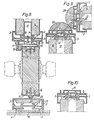
- Figs. 11-13 show an interesting application of the inventive constructional member. It is possible to utilize the basic rail for glass walls as well as window structures, where of course the wall structure is the simpler one in practice.
- Fig. 11 is a cross section through the connection of the glass wall to an upper wall portion, which as with previous structures, consists of a wall member 15 and attachment rail 17, each accommodated their respective channels on the basic rail 1, 2, 3.
- the second channel 9, 10, 5 receives a clamping rail 11 between the corners of which and the respective adjacent supporting leg 4 there is a sheet of glass 27.
- Fig. 11 is a cross section through the connection of the glass wall to an upper wall portion, which as with previous structures, consists of a wall member 15 and attachment rail 17, each accommodated their respective channels on the basic rail 1, 2, 3.
- the second channel 9, 10, 5 receives a clamping rail 11 between the corners of which and the respective adjacent supporting leg 4 there is a sheet of glass 27.
- FIG. 12 shows the glass wall in plan, where the lefthand portion constitutes a connection to a side wall 15, while the righthand portion consists of a pillar, comprising two mutually facing basic rails 1, 2, 3, 1', 2', 3', which are fitted round a supporting body 28, e.g. a steel tube to give the structure its carrying capacity.
- Fig. 13 shows the floor connection of the glass wall, where the sheets of glass 27 rest against elastic support elements 29, and where possible gaps between the glass and constructional member are shown filled with sealing material 30.
- Fig. 14 is a cross section through a window formed with triple glazing, the two outer sheets of glass consisting of an insulation panel 30, rigidly mounted in the window frame, while the inner glazing sheet 32 is hinged.
- the window is mounted in a frame consisting of a basic web portion 1, a fixed leg portion 2 and a removable leg portion 3a or 3b, the latter two including a hinged portion 33 and a locking portion 34, respectively.
- One of the support legs 4 engages against the outside of the facade, while the other is accommodated in a groove in the window wall 36.
- the cavities in the constructional members are suitably filled with a foam plastics material to improve insulation and prevent the occurrence of cold bridges through the frame members.
- the web portion is provided with holes 38 for further preventing the occurrence of cold bridges and to allow the foam material to come into all the cavities in the rail.
- the insulation panel 31 and the inner seals 32 are kept in place by means of supplementary rails, the width of which are adjustable to suit the member positioned by means of clamping action against the leg portions of the basic rail.
- Fig. 15 will be seen the principle for a beam structure in which two basic rails are fitted to each other to form a beam section.
- the surfaces facing each other of the basic supporting legs 4 form a U-section together with the basic web portion 1, this U-section fitting the first channel on another basic rail.
- Fig. 16 shows an alternative beam structure where the basic rails are attached to a support body 28 arranged in the first channels of two basic rails, the leg portions 2 and 3 of which are facing each other.
- Another support body 39 is arranged in the third channel to one of the two basic rails and the third channel of a further basic rail, the support legs 4 of both last- mentioned basic rails facing towards each other.
- this assembly pattern an entire wall can be built up using the inventive constructional member.
Landscapes
- Engineering & Computer Science (AREA)
- Civil Engineering (AREA)
- Structural Engineering (AREA)
- Architecture (AREA)
- Physics & Mathematics (AREA)
- Electromagnetism (AREA)
- Door And Window Frames Mounted To Openings (AREA)
Claims (6)
Applications Claiming Priority (2)
| Application Number | Priority Date | Filing Date | Title |
|---|---|---|---|
| SE7708343 | 1977-07-19 | ||
| SE7708343A SE415588B (sv) | 1977-07-19 | 1977-07-19 | Konstruktionselement for byggnader |
Publications (2)
| Publication Number | Publication Date |
|---|---|
| EP0010086A1 EP0010086A1 (de) | 1980-04-30 |
| EP0010086B1 true EP0010086B1 (de) | 1982-05-26 |
Family
ID=20331887
Family Applications (1)
| Application Number | Title | Priority Date | Filing Date |
|---|---|---|---|
| EP78900051A Expired EP0010086B1 (de) | 1977-07-19 | 1979-02-14 | Bauelement für gebäude |
Country Status (5)
| Country | Link |
|---|---|
| US (1) | US4266387A (de) |
| EP (1) | EP0010086B1 (de) |
| DE (1) | DE2861862D1 (de) |
| SE (1) | SE415588B (de) |
| WO (1) | WO1979000047A1 (de) |
Families Citing this family (26)
| Publication number | Priority date | Publication date | Assignee | Title |
|---|---|---|---|---|
| US4361994A (en) * | 1980-08-11 | 1982-12-07 | Carver Tommy L | Structural support for interior wall partition assembly |
| US4453355A (en) * | 1981-07-28 | 1984-06-12 | Stoakes Richard Lewis | Curtain wall constructions |
| US5699636A (en) * | 1994-12-09 | 1997-12-23 | Newell Manufacturing Company | Extruded window jamb liner with yieldable sealing means |
| US5526608A (en) * | 1994-12-09 | 1996-06-18 | Newell Manufacturing Company | Extruded window jamb liner with yieldable sealing means |
| US6016632A (en) * | 1996-10-28 | 2000-01-25 | Porta-Fab Corporation | Modular wall system |
| RU2120533C1 (ru) * | 1997-06-06 | 1998-10-20 | Открытое акционерное общество Верхнесалдинское металлургическое производственное объединение | Термовкладыш |
| US6122864A (en) * | 1998-01-13 | 2000-09-26 | Amesbury Group, Inc. | Floating weather-strip for use with a fixed jambliner |
| FI107952B (sv) * | 2000-01-14 | 2001-10-31 | Paroc Group Oy Ab | Bågkonstruktion |
| SE0000962D0 (sv) * | 2000-03-21 | 2000-03-21 | Santex Ab | Avslutningsprofil vid fönster- eller väggelement |
| SE0000963D0 (sv) * | 2000-03-21 | 2000-03-21 | Santex Ab | Fastsättningsanordning |
| WO2002036920A2 (es) * | 2000-10-31 | 2002-05-10 | Garay Arellano David Antonio D | Sistema de perfiles de aluminio para la colocacion de puertas, ventanas y muros divisorios |
| US6747340B2 (en) * | 2002-03-15 | 2004-06-08 | Memx, Inc. | Multi-level shielded multi-conductor interconnect bus for MEMS |
| US6761004B2 (en) * | 2002-05-02 | 2004-07-13 | Affordable Building Systems | Reconfigurable room partitioning system |
| NL1021799C2 (nl) * | 2002-10-31 | 2004-05-14 | Teha Holding B V | Kozijn met afdekprofiel. |
| US7694468B2 (en) * | 2003-09-05 | 2010-04-13 | Norman International, Inc. | Window framing system with decorative overlay and method for using the same |
| US20050066581A1 (en) * | 2003-09-26 | 2005-03-31 | Intek Plastics, Inc. | Weather-strip |
| US8024899B2 (en) * | 2004-05-26 | 2011-09-27 | Outlook Window Products, L.L.C. | Apparatus and systems of interior window framing |
| US20060053695A1 (en) * | 2004-09-10 | 2006-03-16 | Palenske Grant A | Integrated adjustable threshold |
| US8096081B2 (en) * | 2005-01-12 | 2012-01-17 | Pella Corporation | Jamb liner for a window assembly |
| US20070125013A1 (en) * | 2005-11-14 | 2007-06-07 | Cuatro, Llc | Finishing system for wall openings |
| CA2643557C (en) * | 2007-11-09 | 2014-04-22 | Dallaire Industries Ltd. | Window cladding |
| US8595996B2 (en) * | 2010-02-26 | 2013-12-03 | General Electric Company | Photovoltaic framed module array mount utilizing asymmetric rail |
| ES2434110B1 (es) * | 2013-05-03 | 2014-09-16 | Kreativer Raum, S.L | Mampara para el cerramiento lineal del interior de edificios |
| WO2019083423A1 (en) * | 2017-10-26 | 2019-05-02 | Qleanair Scandinavia Ab | TRANSPORT STRIP, TRANSPORT FRAME COMPRISING SUCH TRANSPORT STRIPS AND BASE STRIP AND SUPPORT STRIP FORMING SUCH A TRANSPORT STRIP |
| SE542241C2 (sv) * | 2017-10-26 | 2020-03-24 | Qleanair Scandinavia Ab | Sammanlåsningsanordning |
| FR3150519A1 (fr) | 2023-06-28 | 2025-01-03 | Universite Claude Bernard Lyon 1 | Procédé de valorisation des déchets de silicone élastomère pour la production de matériaux silicone recyclés |
Family Cites Families (8)
| Publication number | Priority date | Publication date | Assignee | Title |
|---|---|---|---|---|
| DE969749C (de) * | 1954-01-14 | 1958-07-10 | Maria Grossmann Geb Varilek | Fenster- oder Tuerrahmen aus Metall, insbesondere Leichtmetall, mit einfacher Verglasung, vorzugsweise Verbundtafelverglasung |
| US3140763A (en) * | 1961-03-06 | 1964-07-14 | Bertlo Company Inc | Curtain wall |
| SE393151B (sv) * | 1970-07-06 | 1977-05-02 | Erbsloeh Julius & August | Anordning for framstellning av hopsatta profilramar |
| FR2107391A5 (de) * | 1971-09-01 | 1972-05-05 | Royon Regis | |
| BE779411A (fr) * | 1972-02-16 | 1972-06-16 | Geisler Anciens Ets Ed | Elements de chassis metallique sans pont thermique et/ou acoustique et chassis appliquant ces elements. |
| IT995354B (it) * | 1972-09-16 | 1975-11-10 | Steinmetz G | Finestra o porta di profilati di alluminio |
| JPS5245092Y2 (de) * | 1973-12-03 | 1977-10-13 | ||
| FR2281482A1 (fr) * | 1974-08-06 | 1976-03-05 | Amiaud Pierre | Nouveau profile metallique pour encadrements d'huisseries |
-
1977
- 1977-07-19 SE SE7708343A patent/SE415588B/xx unknown
-
1978
- 1978-07-11 DE DE7878900051T patent/DE2861862D1/de not_active Expired
- 1978-07-11 WO PCT/SE1978/000017 patent/WO1979000047A1/en not_active Ceased
-
1979
- 1979-02-14 EP EP78900051A patent/EP0010086B1/de not_active Expired
- 1979-03-13 US US06/023,195 patent/US4266387A/en not_active Expired - Lifetime
Also Published As
| Publication number | Publication date |
|---|---|
| WO1979000047A1 (en) | 1979-02-08 |
| SE7708343L (sv) | 1979-01-20 |
| US4266387A (en) | 1981-05-12 |
| SE415588B (sv) | 1980-10-13 |
| EP0010086A1 (de) | 1980-04-30 |
| DE2861862D1 (en) | 1982-07-15 |
Similar Documents
| Publication | Publication Date | Title |
|---|---|---|
| EP0010086B1 (de) | Bauelement für gebäude | |
| EP3665337B1 (de) | Trockentrennwandsystem und verfahren zur installation eines trockentrennwandsystems dieser art | |
| RU2046170C1 (ru) | Стена с двумя расположенными на расстоянии друг от друга панелями | |
| US4897976A (en) | Building enclosure assemblies | |
| EP3599332A1 (de) | Modulares system für schiebeelemente in gebäudefassaden | |
| US2904991A (en) | Adjustable, non-load-bearing partition construction | |
| US4833849A (en) | Building enclosure assemblies | |
| US3888059A (en) | Partition wall construction | |
| US4631886A (en) | Method and system for the facing of structures | |
| KR890004177B1 (ko) | 실내공간의 내장 및 칸막이 구조시스템 | |
| RU16509U1 (ru) | Стеновая конструкция | |
| GB2152091A (en) | Suspended ceiling | |
| US3352075A (en) | Movable wall construction of panels held by channels at top and bottom | |
| JPS6317768Y2 (de) | ||
| JP4680078B2 (ja) | 仮設天井およびこれを用いた天井裏空間の施工方法 | |
| WO2022208423A1 (en) | Ceiling grid system | |
| JP2771759B2 (ja) | 建物及び建物の改装方法 | |
| GB2026076A (en) | A dismantable partitioning system | |
| JPH0339523Y2 (de) | ||
| EP0717158A3 (de) | Raumbausteinsystem für das Erstellen von Bauwerken | |
| EP0214378A1 (de) | Innere Zwischenwand | |
| JPH071125U (ja) | 壁パネル | |
| DE69823280T2 (de) | Befestigungsvorrichtung für Paneele einer vertikalen Vorhängewand für Gebäude | |
| GB2146367A (en) | Channel section for rooms of buildings | |
| RO113669B1 (ro) | Set de elemente metalice pentru fixarea unor panouri in constructii |
Legal Events
| Date | Code | Title | Description |
|---|---|---|---|
| PUAI | Public reference made under article 153(3) epc to a published international application that has entered the european phase |
Free format text: ORIGINAL CODE: 0009012 |
|
| AK | Designated contracting states |
Designated state(s): CH DE FR GB |
|
| 17P | Request for examination filed | ||
| GRAA | (expected) grant |
Free format text: ORIGINAL CODE: 0009210 |
|
| PGFP | Annual fee paid to national office [announced via postgrant information from national office to epo] |
Ref country code: FR Payment date: 19820429 Year of fee payment: 5 |
|
| AK | Designated contracting states |
Designated state(s): CH DE FR GB |
|
| REF | Corresponds to: |
Ref document number: 2861862 Country of ref document: DE Date of ref document: 19820715 |
|
| PGFP | Annual fee paid to national office [announced via postgrant information from national office to epo] |
Ref country code: DE Payment date: 19820930 Year of fee payment: 5 Ref country code: CH Payment date: 19820930 Year of fee payment: 5 |
|
| PG25 | Lapsed in a contracting state [announced via postgrant information from national office to epo] |
Ref country code: CH Effective date: 19830731 |
|
| GBPC | Gb: european patent ceased through non-payment of renewal fee | ||
| PG25 | Lapsed in a contracting state [announced via postgrant information from national office to epo] |
Ref country code: FR Free format text: LAPSE BECAUSE OF NON-PAYMENT OF DUE FEES Effective date: 19840330 |
|
| REG | Reference to a national code |
Ref country code: CH Ref legal event code: PL |
|
| PG25 | Lapsed in a contracting state [announced via postgrant information from national office to epo] |
Ref country code: DE Effective date: 19840403 |
|
| REG | Reference to a national code |
Ref country code: FR Ref legal event code: ST |
|
| PG25 | Lapsed in a contracting state [announced via postgrant information from national office to epo] |
Ref country code: GB Effective date: 19881118 |
|
| PLBE | No opposition filed within time limit |
Free format text: ORIGINAL CODE: 0009261 |
|
| STAA | Information on the status of an ep patent application or granted ep patent |
Free format text: STATUS: NO OPPOSITION FILED WITHIN TIME LIMIT |