EP0010201A1 - Bicyclette - Google Patents
Bicyclette Download PDFInfo
- Publication number
- EP0010201A1 EP0010201A1 EP79103638A EP79103638A EP0010201A1 EP 0010201 A1 EP0010201 A1 EP 0010201A1 EP 79103638 A EP79103638 A EP 79103638A EP 79103638 A EP79103638 A EP 79103638A EP 0010201 A1 EP0010201 A1 EP 0010201A1
- Authority
- EP
- European Patent Office
- Prior art keywords
- shaft
- hub
- rear wheel
- gear
- wheel
- Prior art date
- Legal status (The legal status is an assumption and is not a legal conclusion. Google has not performed a legal analysis and makes no representation as to the accuracy of the status listed.)
- Granted
Links
Images


Classifications
-
- B—PERFORMING OPERATIONS; TRANSPORTING
- B62—LAND VEHICLES FOR TRAVELLING OTHERWISE THAN ON RAILS
- B62M—RIDER PROPULSION OF WHEELED VEHICLES OR SLEDGES; POWERED PROPULSION OF SLEDGES OR SINGLE-TRACK CYCLES; TRANSMISSIONS SPECIALLY ADAPTED FOR SUCH VEHICLES
- B62M11/00—Transmissions characterised by the use of interengaging toothed wheels or frictionally-engaging wheels
- B62M11/04—Transmissions characterised by the use of interengaging toothed wheels or frictionally-engaging wheels of changeable ratio
-
- B—PERFORMING OPERATIONS; TRANSPORTING
- B62—LAND VEHICLES FOR TRAVELLING OTHERWISE THAN ON RAILS
- B62K—CYCLES; CYCLE FRAMES; CYCLE STEERING DEVICES; RIDER-OPERATED TERMINAL CONTROLS SPECIALLY ADAPTED FOR CYCLES; CYCLE AXLE SUSPENSIONS; CYCLE SIDECARS, FORECARS, OR THE LIKE
- B62K3/00—Bicycles
- B62K3/02—Frames
- B62K3/04—Frames having a substantially horizontal top bar
Definitions
- the invention relates to a bicycle having a frame which is supported on a front wheel held in a steering fork and on a rear wheel which is preferably driven via pedals with crank arms which are fastened to a rotatably mounted shaft and which has a y hub with a freewheel.
- a bottom bracket is provided, which receives the crankshaft shaft, which is connected to the rear wheel hub via a chain drive.
- This chain drive often causes contamination of the person operating the pedals despite a complex chain guard.
- there is a risk that items of clothing of the person operating the pedals will be drawn in between the chain and the sprocket, which not only results in considerable damage, but also an extremely high risk of accidents.
- the here between the front wheel Bottom bracket and rear wheel arranged in the known arrangements also results in a relatively large vehicle length and, as a result, also a relatively large vehicle weight.
- a very particular disadvantage of the known arrangements is that here the saddle assigned to the person operating the pedals cannot be arranged directly above the bottom bracket for maneuvering an approximately usable load distribution, so that the person operating the pedals is not easy to operate the pedals can step down, which would suggest the highest performance and a healthy posture.
- the rear wheel hub is penetrated centrally by the shaft provided with crank arms and can be rotatably connected to it by means of at least one transmission gear unit, and in that the shaft is supported on the hub laterally projecting bearing bodies, via which the rear wheel outside the shaft with the Bicycle frame can be screwed, which has a saddle arranged approximately vertically above the rear wheel hub and approximately vertically extending rear wheel supports.
- the measures according to the invention thus ensure that the normal upright posture when walking, in which humans can achieve a high level of performance, is also maintained when cycling, which consequently not only results in a high lei can be expected, but at the same time enables a healthy posture, since the abdominal region is not compressed.
- Another advantage of the measures according to the invention can be seen in the fact that the frame is shortened compared to known arrangements and at the same time can be made relatively light in the less heavily loaded areas. As a result of the weight absorption practically above the rear wheel hub, bending loads on the struts are also largely eliminated, so that overall a highly desirable weight saving can be achieved.
- the hub and the shaft can be supported on both sides with a bearing on each of the bearing bodies provided on the side, which enables simple construction and thus economical manufacture and assembly and nevertheless ensures reliable force absorption.
- Another expedient measure can consist in that the shaft passing through the hub is provided directly with a brake thread or the like to form a coaster brake, in which a brake body engages, by means of which a brake jacket interacting with a cone can be brought to bear against the hub. Due to the direct arrangement of the brake thread on the shaft, it is ensured that a high brake force is reached, since no reduction achieved by the gearbox has to be taken into account.
- the bicycle shown in Figure 1 consists of a frame designated as a whole by 1, which is supported on a front wheel 2 and a rear wheel 3.
- the Front wheel 2 is received in a steering fork 4.
- the rear wheel 3 can be driven directly, ie without a chain drive, via pedals 6 attached to crank arms 5.
- the crank arms 5 are connected via a shaft indicated at 7, which passes through the rear wheel hub indicated at 8 and can be rotatably coupled thereto, as will be explained in more detail below.
- the frame 1 is supported on the rear wheel with fork-shaped rear wheel supports 9 which extend approximately vertically upwards from the hub 8 receiving the shaft 7 and at the upper end of which a saddle 10 is arranged, on which the person operating the pedals 6 can sit .
- the saddle 10 Since the saddle 10 is arranged practically vertically above the shaft connecting the crank arms 5, the person sitting on the saddle 10 can actuate the pedals 6 in a practically upright position, which can be done simply by shifting weight.
- the front wheel 2 is comparatively little loaded, which allows easy steering. It is sufficient if only the rear wheel supports 9, which are practically subjected to buckling, are designed to be sufficiently strong.
- the other frame parts can be carried out relatively easily.
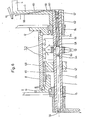
- the rear wheel 3 as can best be seen from FIGS. 2 and 3, is screwed outside the shaft 7 passing through the hub 8 to the rear wheel supports 9 or with receiving rings 11 fastened thereon, on which further frame parts, such as cross struts etc., can engage.
- the bearing rings 11 are assigned bearing bodies 12 or 13 projecting beyond the end faces of the hub 8 on the rear wheel side, which have corresponding bores for receiving the ones shown in FIG Connecting screws 14 are provided.
- the bearing bodies 12 and 13 are provided with an aligned central bore in which the shaft 7 is freely rotatably supported by means of ball bearings.
- a bearing arrangement according to FIG. 3 is preferred, in which only one bearing is provided on each side.
- the shaft 7 can be provided on the one hand with a fixed bearing ring 15 and on the other hand with a bearing ring which can be adjusted, for example, by means of a thread, as shown in FIG. 2.
- both bearing rings 15 and 16 are adjustable and can be fixed by means of a lock nut.
- the shaft 7 connecting the crank arms 5 to each other is connected to the hub 8 via a gear unit designated here as a whole by 17, which is intended to effect a speed ratio.
- a gear transmission can simply be provided for this purpose.
- a planetary gear is provided to form the single-speed gear formed by the gear unit 17, which advantageously results in the same directions of rotation of shaft 7 and hub 8 without further measures.
- the shaft 7 is arranged centrally in the hub 8 and is provided with a planet gear holder 18 which is expediently designed as a radial flange and which is to be equipped on the periphery with three planet gears of the type indicated at 19.
- the planet gears 19 are rotatably mounted on assigned bolts 20 and stand on the one hand with a frame-fixed, that is to say fixed outer ring gear 21 and on the other hand with a freely rotatable inner tooth wreath 22 in engagement.
- the outer ring gear 21 is simply molded onto a laterally projecting collar 23 of the adjacent bearing body 12 screwed to the bicycle frame.
- the inner, driven ring gear 22 is integrally formed on an annular body designated as a whole by 31, which in turn is freely rotatably mounted on the shaft 7.
- a needle bearing can expediently be used.
- the ring body 31 for transmitting the torque to the hub 8 is provided with a bush 24 which projects on the side opposite the gear unit 17 and which has a circumferential thread 30 and onto which a freewheel clamping body 25 is screwed, with a driving flange on the hub side 26 is assigned.
- the freewheel body 25 and the driving flange 26 can be provided with opposing inclined surfaces.
- the annular free-wheel clamping body 25 is surrounded by a brake jacket 27, to which a frame-fixed starting cone 28 is assigned.
- the starting cone 28 is simply molded onto the lateral bearing body 13.
- the annular body 31 is to be coupled to the hub 8 via peripherally arranged free-wheel members 32, such as free-running rollers or pawls, which allows a very simple and compact design.
- freewheel members 32 bring about that no torque is transmitted from the hub 8 to the shaft 7 and, on the other hand, even when stepping back or turning back the shaft 7, for example for braking purposes, there is no entrainment in the region of the freewheel rollers or pawls.
- the shaft 7 in an embodiment of this type can be provided in a particularly advantageous manner with a directly formed thread 67 or similar guide surfaces, into which an annular brake body 68 engages, which in a manner known per se has a brake jacket 69 actuated, which, when the shaft 7 is turned back, runs onto a cone, which is also formed on the bearing body 13 here, is thereby widened and brought to the braking system on the hub 8.
- a brake jacket 69 actuated, which, when the shaft 7 is turned back, runs onto a cone, which is also formed on the bearing body 13 here, is thereby widened and brought to the braking system on the hub 8.
- Darge provided pin-slot connection in the region of the bearing body 13 may be provided.
- the direct mounting of the brake body 68 on the central shaft 7, which is driven here obviously results in a high braking force since there is no reduction, which would be the case with a power flow running via a gear unit 17.
- the hub 8 is supported on two ball bearings.
- the hub 8 is supported directly on the fixed bearing bodies 12 and 13 by the two ball bearings.
- the hub 8 is supported on the one hand on the bearing body 13 and on the other hand on a radial support flange 29 of the driven ring body 31, which results in excellent support in the vicinity of the driving flange 26 required here.
- the support flange 29 can in turn be supported on the adjacent collar 23 of the bearing body 12, which advantageously also results in an exact axial fixation of the annular body 31 receiving the driven inner ring gear 22.
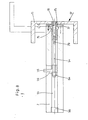
- the shaft 7 which can be driven via the pedals 6 is connected in terms of drive to the wheel hub 8 via a three-speed gearbox, designated as a whole by 47.
- a three-speed gearbox designated as a whole by 47.
- an annular body 31 which is freely rotatably mounted thereon and surrounds the shaft 7 and which interacts with the hub 8 via free-wheel members 32, for example free-wheel rollers or pawls, is arranged.
- Said gearbox 47 has a hollow shaft 43 which is arranged approximately perpendicular to shaft 7 and which is freely rotatable in a housing-fixed component, here the side bearing body 12, is mounted.
- the hollow shaft 33 can be overhung.
- the hollow shaft 33 is supported on two sides, for which purpose the bearing body 12 has a suitable profile which is approximately U-shaped in cross section.
- the hollow shaft 33 is equipped at its end facing the shaft 7 with a bevel gear 34 which cooperates with a bevel gear 35 seated on the shaft 7.
- a bevel gear 34 which cooperates with a bevel gear 35 seated on the shaft 7.
- several, here three wheels 36 are arranged side by side at different distances from the axis of the shaft 7 and thus also from the axis of the annular body 31 concentrically surrounding the shaft 7 to form several gears.
- the wheels 36 are freely rotatable on the hollow shaft and each have a groove 37 in the area of their bearing bore. These wheels 36 are individually rotatably connected to the hollow shaft 33.
- the hollow shaft 33 is penetrated by an outwardly guided switching rod 38, which is connected at its end projecting into the hollow shaft 33 via a rotary coupling to a sliding member 39.
- This slide member 39 is provided with a nose 40 which engages through a slot-shaped recess 41 of the hollow shaft 33 and into the groove 37 of a wheel 36 in each case.
- the shift rod 38 can be actuated here simply by means of a cable pull (not shown in more detail) which is guided, for example, to the bicycle handlebar, against the force of a return spring indicated at 42. Since the hollow shaft 33 is mounted in a component that is fixed to the frame, the circuit cable can easily be laid fixed to the frame. With the aid of the sliding member 39, one of the wheels 36 can be seen to be connected to the hollow shaft 33 in a rotationally locking manner.
- the wheels 36 are in engagement with the ring body 31 already mentioned above.
- the ring body 31 expediently has a flange 43 which is approximately parallel to the hollow shaft and which can advantageously be supported on the adjacent ring body 12 and on which the torque emitted by the hollow shaft, depending on which of the wheels 36 is activated, can be introduced in tracks of different diameters.
- the wheels 36 can be designed as friction wheels.
- the drive flange 43 of the ring body 31 is expediently provided with suitable friction surfaces.
- the wheels 36 are designed as gear wheels.
- the flange 43 of the ring body 31 is provided with three toothed rings 44 assigned to the wheels 36.
- the distance between the wheels 36 is expediently chosen such that only one wheel is activated in each position of the displacement member 39.
- the annular body 31 is, as has already been explained above, coupled to the hub 8 via a freewheel.
- the hollow shaft 33 is also rotated via the bevel gear set 34, 35.
- the wheel 36 of the gear set which is rotatably connected to the hollow shaft 33 by means of the displacement member 39, transmits the rotational movement to the ring body 31, which in turn transmits the rotational movement to the hub 8.
- the torque is introduced into this at a greater or lesser distance from the axis of the ring body 31, which clearly shows a difference translation ratios.
- only one set of wheels is provided on the circumference of the shaft 7.
- the ring body 31 can here, similar to the embodiment according to FIG. 2, have a projecting bush on the side opposite the drive flange 43, which is provided on its circumference with a brake thread 30 or similar guide surfaces into which a screwed-on brake body (not shown here) is provided engages, which, when the direction of rotation of the shaft 7 is reversed, is pushed onto a starting cone provided here in the area of the adjacent bearing body 13, thereby widened and brought into abutment on the hub 8 to be braked.
- a brake thread or similar guide surfaces similar to the embodiment according to FIG. 3.
- FIG. 5 instead of a plurality of wheels axially secured on the hollow shaft 33, which can be activated individually by the sliding member, ie can be connected to the hollow shaft 7 in a rotationally locking manner, but otherwise can simply rotate freely in the non-activated state, only one Wheel 45, expediently a friction wheel, is provided which is axially displaceably mounted on the hollow shaft 33 and is fixedly connected to the displacement member 39, ie in the direction of the axis of the latter Hollow shaft 33 can be moved.
- the shift rod 38 is actuated, the distance of the wheel 45 from the axis of the ring body 31 is continuously changed, which practically allows a continuous change in the gear ratio.
- the wheel 45 should be designed as a friction wheel.
- the drive flange 43 of the ring body 31 can expediently be provided with an annular friction lining 46. Otherwise, the design of this exemplary embodiment corresponds to the arrangement according to FIG. 4. If a gearwheel is provided instead of the friction wheel 45, the drive flange 43 is provided with a gear rim per gear.
- FIGS. 6 to 8 in order to form a multi-speed, here two-speed manual gearbox, two gear units, designated as a whole by 50, for reasons of space, represented by boxes 7 and penetrated by shaft 7, are arranged next to one another, which roughly corresponds to that in connection with FIG 3 can correspond to the gear unit 17 described in detail.
- the rest of the structure also roughly corresponds to the arrangement according to FIG. 3.
- the following explanations are therefore essentially limited to the further developments that are available in comparison, the same reference numerals being used for the same parts or parts with the same function for the sake of clarity.
- a coupling ring 52 which is axially displaceable on the shaft 7 and which is expediently in positive engagement with a corresponding link of the gear units 50 is feasible.
- the coupling ring 52 is provided with claws 53 arranged on the end. It is conceivable to use this coupling ring to couple the planet gear carrier, which is otherwise freely rotatable with respect to the shaft 7, to the shaft.
- the clutch ring 52 is axially displaceable by means of a shift rod 54 accommodated in the shaft 7 and can thus be brought into or out of engagement with each of the two gear units 50 flanking it.
- the shaft 7 is designed as a hollow shaft.
- the shaft 7 is simply provided with a continuous central bore 55 for this purpose.
- the bore 55 can be closed in the area of the shaft end faces by suitable covers etc.
- threaded plugs 56 and 57 are simply screwed into the bore 50 to close them.
- the push rod 54 is provided with a radially projecting driver lug 58 which extends through a slot-shaped recess 59 of the shaft 7 and is fixedly connected to the coupling ring 52. In the area of its end opposite the driving lug 58, the shift rod 54 is connected to a cable pull 60, which is only indicated here by its center line.
- the cable pull 6O is led out of the shaft 7 and connected in the region of its outer end to a foot switch 61 indicated at 61 and arranged in the region of the pedal 6.
- the foot switch 61 can be designed, for example, as a toggle lever which can be snapped into different switching positions.
- the shift rod 54 is by means of the foot shift lever 61 axially adjustable against the force of a return spring indicated at 62 and thus brought into or out of engagement with the gear units 50.
- the return spring 62 is designed as a compression spring surrounding the switching rod 54, which is supported on the one hand on a thickening 63 of the switching rod 54 and on the other hand on the threaded plug 57 penetrated by the cable pull 60.
- the thickening 63 simultaneously ensures adequate guidance of the shift rod 54.
- the return spring it would also be easily conceivable to design the return spring as a tension spring, which could expediently be arranged in the area of the bore 55 not penetrated by the shift rod 54.
- the diameter of the shift rod 54 could correspond over its entire length to the diameter of the bore 55, which could enable simple manufacture, a compact design and excellent large-area guidance.
- the shift rod 54 and the lug-side thickening 63 can be designed as separate components provided with a thread engagement. In the ps entrybeispiel shown an adjusting screw indicated at 64 is provided for this.
- the latter In order to guide the cable pull 60 in the region of the crank arm 5, the latter is provided with an oblique bore 65 which runs from the bottom outside inwards and in which the cable pull 60 is laid.
- the bore 65 can extend approximately from the area of the hub of the pedal crank 5 assigned to the shaft 7 to the area of the foot control lever 61.
- the bore 65 opens in the region of its ends into grooves 66, in which the cable pull 60 outside the bore 65 is protected.
- the shift rod 54 accommodated in the shaft 7, which is equipped with a driving lug 58 which extends through a slot-shaped recess 59 of the shaft 7, is as a whole via a rotary coupling indicated at 70 with a freely rotatable counter-rotating 61 designated foot control lever connected.
- this foot switch lever 61 is provided with two arms 71 which are bent like a pedal at their ends and which extend in a plane approximately parallel to the plane of the adjacent pedal crank arm 5.
- a space curve 63 is scanned by the shift lever 61, which is rotatable relative to the shift rod 54, with a corresponding elevation or depression in the axial direction.
- the curve 63 is formed directly on an end face of the shaft 7, which results in a simple and compact design.
- the arms 71 of the foot switch lever 61 can be provided with locking teeth of the type indicated at 72, to which suitable locking troughs 73 can be assigned to define the desired switching positions.
- the locking troughs 73 are simply provided in the area of the pedal crank arms 5. However, it would also be easily conceivable to provide a larger segment for receiving the locking troughs.
- an adjusting screw 64 is also provided, on which the driving lug 58 is ge by the force of the return spring indicated at 62 is brought.
- the foot-operated lever also designated as a whole here with 61 and having two pedal-like bent arms 71, is wedged on a pivot pin 75 which is rotatably but axially fixed to the shaft 7 by means of a molded collar 76.
- the shaft 7 is simply provided on the end face with a recess receiving the collar 76 and covered by a cover 77.
- the pivot pin 75 is provided with a threaded bore 78 into which a threaded pin 79 formed on the shift rod 54 engages.
- the shift rod 54 cannot be rotated with respect to the shaft 7 due to its fixed connection with the driver lug 58 which extends through a slot-shaped recess 59 of the shaft 7.
- the threaded pin 79 of the shift rod 54 thus screws more or less far into the associated threaded bore 78 of the pin 75 wedged with the foot switch lever 61, thereby causing a. axial adjustment of the shift rod 54 and thus the driving lug 58 is accomplished.
- An adjusting screw 64 can again be provided for the axial adjustment of the driving lug 58.
- a return spring is practically not required in an embodiment of this type.
- the bore 55 of the shaft 7 can therefore easily be designed as a blind bore. In the exemplary embodiment shown, for the sake of simplicity, the bore 55 is designed as a continuous bore which is closed by means of a screw plug 56.
- a latching device with latching teeth 72 and latching recesses 73 can also be provided in one embodiment of the type here.
Landscapes
- Engineering & Computer Science (AREA)
- Mechanical Engineering (AREA)
- Chemical & Material Sciences (AREA)
- Combustion & Propulsion (AREA)
- Transportation (AREA)
- Structure Of Transmissions (AREA)
Priority Applications (1)
| Application Number | Priority Date | Filing Date | Title |
|---|---|---|---|
| AT79103638T ATE1602T1 (de) | 1978-09-27 | 1979-09-25 | Fahrrad. |
Applications Claiming Priority (6)
| Application Number | Priority Date | Filing Date | Title |
|---|---|---|---|
| DE19782841992 DE2841992A1 (de) | 1978-09-27 | 1978-09-27 | Fahrrad |
| DE2841992 | 1978-09-27 | ||
| DE2901966 | 1979-01-19 | ||
| DE19792901966 DE2901966A1 (de) | 1979-01-19 | 1979-01-19 | Fahrrad |
| DE19792901967 DE2901967A1 (de) | 1979-01-19 | 1979-01-19 | Fahrrad |
| DE2901967 | 1979-01-19 |
Publications (2)
| Publication Number | Publication Date |
|---|---|
| EP0010201A1 true EP0010201A1 (fr) | 1980-04-30 |
| EP0010201B1 EP0010201B1 (fr) | 1982-09-29 |
Family
ID=27187688
Family Applications (1)
| Application Number | Title | Priority Date | Filing Date |
|---|---|---|---|
| EP79103638A Expired EP0010201B1 (fr) | 1978-09-27 | 1979-09-25 | Bicyclette |
Country Status (4)
| Country | Link |
|---|---|
| EP (1) | EP0010201B1 (fr) |
| JP (1) | JPS55500820A (fr) |
| DE (1) | DE2963780D1 (fr) |
| WO (1) | WO1980000684A1 (fr) |
Cited By (7)
| Publication number | Priority date | Publication date | Assignee | Title |
|---|---|---|---|---|
| EP0154118A3 (fr) * | 1984-01-16 | 1987-03-04 | TOUR MECCANICA S.r.l. | Vélo de course |
| US4694708A (en) * | 1986-05-15 | 1987-09-22 | Hartmann Dirck T | Single speed transmission for pedal-propelled vehicle |
| FR2596012A1 (fr) * | 1986-03-20 | 1987-09-25 | Cecillon Miguel | Bicyclette adaptee a la morphologie d'un sujet donne |
| US4721015A (en) * | 1986-09-08 | 1988-01-26 | Hartmann Dirck T | Three stage planetary driving wheel for pedal powered vehicles |
| EP0945334A3 (fr) * | 1998-03-25 | 2000-09-06 | Antonio Romeo | Bicyclette avec roue avant motrice et roue arrière de direction |
| CN101282870B (zh) * | 2005-11-17 | 2010-11-03 | 保户田秀男 | 自行车 |
| DE102011122836A1 (de) | 2011-10-17 | 2013-04-18 | Karsten Bettin | Kompaktes, zusammenklappbares Fahrrad |
Families Citing this family (6)
| Publication number | Priority date | Publication date | Assignee | Title |
|---|---|---|---|---|
| DE3316481A1 (de) * | 1983-05-05 | 1984-11-08 | Franz 8104 Grainau Brückl | Fahrrad |
| US5271635A (en) * | 1992-09-11 | 1993-12-21 | Lu Teng Hui | Chainless bicycle having a front wheel resilient suspension |
| CA2078074A1 (fr) * | 1992-09-11 | 1994-03-12 | Teng-Hui Lu | Dispositif stabilisateur pour roue avant de bicyclette sans chaine |
| US5403027A (en) * | 1993-08-27 | 1995-04-04 | Hwang; Chul | Bicycle with folding frame |
| CN101954942B (zh) * | 2009-07-20 | 2013-03-27 | 刘新广 | 后轮导向无链自行车 |
| DE102021128816B3 (de) | 2021-11-05 | 2023-03-30 | Olcay Duman | Fahrrad mit kettenlosem Antrieb |
Citations (6)
| Publication number | Priority date | Publication date | Assignee | Title |
|---|---|---|---|---|
| DE138824C (fr) * | 1900-01-01 | |||
| FR493509A (fr) * | 1900-01-01 | |||
| FR411607A (fr) * | 1910-01-15 | 1910-06-21 | Marcel Noel | Bicyclette sans chaine |
| FR477253A (fr) * | 1913-11-11 | 1915-10-08 | Franz Miller | Bicyclette |
| FR876657A (fr) * | 1940-11-11 | 1942-11-12 | Transmission sans chaîne pour bicyclettes | |
| FR2366491A1 (fr) * | 1976-10-04 | 1978-04-28 | Rinaldi Giovanna | Dispositif de transmission du mouvement a rapport variable, entre des organes tournants |
-
1979
- 1979-09-25 EP EP79103638A patent/EP0010201B1/fr not_active Expired
- 1979-09-25 WO PCT/EP1979/000073 patent/WO1980000684A1/fr not_active Ceased
- 1979-09-25 DE DE7979103638T patent/DE2963780D1/de not_active Expired
- 1979-09-25 JP JP50164879A patent/JPS55500820A/ja active Pending
Patent Citations (6)
| Publication number | Priority date | Publication date | Assignee | Title |
|---|---|---|---|---|
| DE138824C (fr) * | 1900-01-01 | |||
| FR493509A (fr) * | 1900-01-01 | |||
| FR411607A (fr) * | 1910-01-15 | 1910-06-21 | Marcel Noel | Bicyclette sans chaine |
| FR477253A (fr) * | 1913-11-11 | 1915-10-08 | Franz Miller | Bicyclette |
| FR876657A (fr) * | 1940-11-11 | 1942-11-12 | Transmission sans chaîne pour bicyclettes | |
| FR2366491A1 (fr) * | 1976-10-04 | 1978-04-28 | Rinaldi Giovanna | Dispositif de transmission du mouvement a rapport variable, entre des organes tournants |
Cited By (10)
| Publication number | Priority date | Publication date | Assignee | Title |
|---|---|---|---|---|
| EP0154118A3 (fr) * | 1984-01-16 | 1987-03-04 | TOUR MECCANICA S.r.l. | Vélo de course |
| FR2596012A1 (fr) * | 1986-03-20 | 1987-09-25 | Cecillon Miguel | Bicyclette adaptee a la morphologie d'un sujet donne |
| US4694708A (en) * | 1986-05-15 | 1987-09-22 | Hartmann Dirck T | Single speed transmission for pedal-propelled vehicle |
| US4721015A (en) * | 1986-09-08 | 1988-01-26 | Hartmann Dirck T | Three stage planetary driving wheel for pedal powered vehicles |
| EP0945334A3 (fr) * | 1998-03-25 | 2000-09-06 | Antonio Romeo | Bicyclette avec roue avant motrice et roue arrière de direction |
| CN101282870B (zh) * | 2005-11-17 | 2010-11-03 | 保户田秀男 | 自行车 |
| DE102011122836A1 (de) | 2011-10-17 | 2013-04-18 | Karsten Bettin | Kompaktes, zusammenklappbares Fahrrad |
| DE102011055748A1 (de) | 2011-10-17 | 2013-04-18 | Karsten Bettin | Kompaktes zusammenklappbares Fahrrad |
| WO2013056702A1 (fr) | 2011-10-17 | 2013-04-25 | Bettin Karsten | Bicyclette compacte pliable |
| US9051021B2 (en) | 2011-10-17 | 2015-06-09 | Karsten Bettin | Compact, collapsible bicycle |
Also Published As
| Publication number | Publication date |
|---|---|
| JPS55500820A (fr) | 1980-10-23 |
| WO1980000684A1 (fr) | 1980-04-17 |
| EP0010201B1 (fr) | 1982-09-29 |
| DE2963780D1 (en) | 1982-11-11 |
Similar Documents
| Publication | Publication Date | Title |
|---|---|---|
| DE3407164C2 (de) | Mehrgang-Antriebsnabe für Fahrräder | |
| DE69903659T2 (de) | Kraftübertragungsvorrichtung mit Schaltstellungsanzeige | |
| EP0010201A1 (fr) | Bicyclette | |
| DE2752737A1 (de) | Fahrrad-schaltnabe | |
| DE2934588A1 (de) | Pedalbetaetigte bremsensteuervorrichtung fuer fahrraeder | |
| DE3877966T2 (de) | Anordnung fuer fahrraeder, welche selbsttaetig die bremsfunktion beim rueckdrehen des antriebsrades beseitigt. | |
| DE3933771A1 (de) | Elektromotorische servolenkung | |
| DE3838359C2 (fr) | ||
| DE602005003547T2 (de) | Fahrradantriebsnabe | |
| DE19516216C2 (de) | Fahrzeug mit Schubkurbelantrieb | |
| DE2410679A1 (de) | Vom benutzer angetriebenes feuerzeug | |
| DE10127094C1 (de) | Schaltwerksgetriebe mit veränderlicher Übersetzung, insbesondere für Fahrräder | |
| DE3039024A1 (de) | Gangschalthebel fuer fahrrad-kettenschaltung | |
| AT396743B (de) | Krankenfahrstuhl | |
| DE2901967A1 (de) | Fahrrad | |
| DE3408544A1 (de) | Muskelgetriebenes fortbewegungsmittel fuer personen | |
| WO1999037529A9 (fr) | Derailleur automatique de bicyclette | |
| DE8507021U1 (de) | Dreirad, insbesondere für behinderte Personen | |
| DE3904786A1 (de) | Durch gegentreten betaetigte zweiradbremse | |
| DE3348148C2 (en) | Muscle-powered vehicle | |
| DE3744420C2 (de) | Steuereinrichtung für eine von einem Verbrennungsmotor angetriebenes hydrostatisches Getriebe | |
| DE1036074B (de) | In der Laenge veraenderlicher Lenkturm fuer vorzugsweise landwirtschaftliche Kraftfahrzeuge | |
| DE2727488A1 (de) | Bremseinheit | |
| DE2841992A1 (de) | Fahrrad | |
| DE3727933A1 (de) | Kettenschalteinrichtung fuer fahrraeder |
Legal Events
| Date | Code | Title | Description |
|---|---|---|---|
| PUAI | Public reference made under article 153(3) epc to a published international application that has entered the european phase |
Free format text: ORIGINAL CODE: 0009012 |
|
| AK | Designated contracting states |
Designated state(s): AT DE FR GB IT NL |
|
| 17P | Request for examination filed |
Effective date: 19801025 |
|
| ITF | It: translation for a ep patent filed | ||
| GRAA | (expected) grant |
Free format text: ORIGINAL CODE: 0009210 |
|
| AK | Designated contracting states |
Designated state(s): AT DE FR GB IT NL |
|
| PG25 | Lapsed in a contracting state [announced via postgrant information from national office to epo] |
Ref country code: NL Effective date: 19820929 Ref country code: FR Free format text: THE PATENT HAS BEEN ANNULLED BY A DECISION OF A NATIONAL AUTHORITY Effective date: 19820929 |
|
| REF | Corresponds to: |
Ref document number: 1602 Country of ref document: AT Date of ref document: 19821015 Kind code of ref document: T |
|
| REF | Corresponds to: |
Ref document number: 2963780 Country of ref document: DE Date of ref document: 19821111 |
|
| NLV1 | Nl: lapsed or annulled due to failure to fulfill the requirements of art. 29p and 29m of the patents act | ||
| EN | Fr: translation not filed | ||
| PG25 | Lapsed in a contracting state [announced via postgrant information from national office to epo] |
Ref country code: AT Effective date: 19830925 |
|
| GBPC | Gb: european patent ceased through non-payment of renewal fee | ||
| PG25 | Lapsed in a contracting state [announced via postgrant information from national office to epo] |
Ref country code: DE Effective date: 19840519 |
|
| PG25 | Lapsed in a contracting state [announced via postgrant information from national office to epo] |
Ref country code: GB Effective date: 19881118 |
|
| PLBE | No opposition filed within time limit |
Free format text: ORIGINAL CODE: 0009261 |
|
| STAA | Information on the status of an ep patent application or granted ep patent |
Free format text: STATUS: NO OPPOSITION FILED WITHIN TIME LIMIT |