EP0010221B1 - Appareil de mesure à fibres optiques - Google Patents
Appareil de mesure à fibres optiques Download PDFInfo
- Publication number
- EP0010221B1 EP0010221B1 EP19790103755 EP79103755A EP0010221B1 EP 0010221 B1 EP0010221 B1 EP 0010221B1 EP 19790103755 EP19790103755 EP 19790103755 EP 79103755 A EP79103755 A EP 79103755A EP 0010221 B1 EP0010221 B1 EP 0010221B1
- Authority
- EP
- European Patent Office
- Prior art keywords
- light
- measuring
- transmitter
- measuring device
- fiber
- Prior art date
- Legal status (The legal status is an assumption and is not a legal conclusion. Google has not performed a legal analysis and makes no representation as to the accuracy of the status listed.)
- Expired
Links
- 239000000835 fiber Substances 0.000 title claims description 41
- 230000003287 optical effect Effects 0.000 claims description 8
- 238000006243 chemical reaction Methods 0.000 claims description 7
- 239000004020 conductor Substances 0.000 claims description 5
- 239000000463 material Substances 0.000 claims description 5
- 239000000696 magnetic material Substances 0.000 claims description 3
- 238000010438 heat treatment Methods 0.000 claims description 2
- 230000035945 sensitivity Effects 0.000 claims description 2
- 230000003019 stabilising effect Effects 0.000 claims 3
- 230000004907 flux Effects 0.000 claims 2
- 230000005693 optoelectronics Effects 0.000 claims 1
- 229920005597 polymer membrane Polymers 0.000 claims 1
- 238000005259 measurement Methods 0.000 description 9
- 238000011156 evaluation Methods 0.000 description 5
- XEEYBQQBJWHFJM-UHFFFAOYSA-N Iron Chemical compound [Fe] XEEYBQQBJWHFJM-UHFFFAOYSA-N 0.000 description 4
- 230000000694 effects Effects 0.000 description 3
- 230000010287 polarization Effects 0.000 description 3
- 229920000642 polymer Polymers 0.000 description 3
- 230000005540 biological transmission Effects 0.000 description 2
- 230000015572 biosynthetic process Effects 0.000 description 2
- 239000013078 crystal Substances 0.000 description 2
- 238000006073 displacement reaction Methods 0.000 description 2
- 229910052742 iron Inorganic materials 0.000 description 2
- 230000001629 suppression Effects 0.000 description 2
- 230000032683 aging Effects 0.000 description 1
- 238000005452 bending Methods 0.000 description 1
- 230000007423 decrease Effects 0.000 description 1
- 238000011161 development Methods 0.000 description 1
- 230000018109 developmental process Effects 0.000 description 1
- 230000005684 electric field Effects 0.000 description 1
- 230000007613 environmental effect Effects 0.000 description 1
- 239000013307 optical fiber Substances 0.000 description 1
- 210000000056 organ Anatomy 0.000 description 1
- 229920006254 polymer film Polymers 0.000 description 1
Images


Classifications
-
- G—PHYSICS
- G01—MEASURING; TESTING
- G01D—MEASURING NOT SPECIALLY ADAPTED FOR A SPECIFIC VARIABLE; ARRANGEMENTS FOR MEASURING TWO OR MORE VARIABLES NOT COVERED IN A SINGLE OTHER SUBCLASS; TARIFF METERING APPARATUS; MEASURING OR TESTING NOT OTHERWISE PROVIDED FOR
- G01D5/00—Mechanical means for transferring the output of a sensing member; Means for converting the output of a sensing member to another variable where the form or nature of the sensing member does not constrain the means for converting; Transducers not specially adapted for a specific variable
- G01D5/26—Mechanical means for transferring the output of a sensing member; Means for converting the output of a sensing member to another variable where the form or nature of the sensing member does not constrain the means for converting; Transducers not specially adapted for a specific variable characterised by optical transfer means, i.e. using infrared, visible, or ultraviolet light
- G01D5/268—Mechanical means for transferring the output of a sensing member; Means for converting the output of a sensing member to another variable where the form or nature of the sensing member does not constrain the means for converting; Transducers not specially adapted for a specific variable characterised by optical transfer means, i.e. using infrared, visible, or ultraviolet light using optical fibres
-
- G—PHYSICS
- G01—MEASURING; TESTING
- G01R—MEASURING ELECTRIC VARIABLES; MEASURING MAGNETIC VARIABLES
- G01R15/00—Details of measuring arrangements of the types provided for in groups G01R17/00 - G01R29/00, G01R33/00 - G01R33/26 or G01R35/00
- G01R15/14—Adaptations providing voltage or current isolation, e.g. for high-voltage or high-current networks
- G01R15/24—Adaptations providing voltage or current isolation, e.g. for high-voltage or high-current networks using light-modulating devices
- G01R15/248—Adaptations providing voltage or current isolation, e.g. for high-voltage or high-current networks using light-modulating devices using a constant light source and electro-mechanically driven deflectors
Definitions
- the invention relates to a fiber optic measuring device for current and / or voltage measurement according to the preamble of claim 1.
- a measuring device is known from DE-AS 1 930111.
- the measuring device known from DE-AS 1 930111 is primarily used to measure the movement of parts that move against one another. The movement of one of these parts can also take place as a function of an electrical variable.
- the light coming from the light source is fed at the measuring point to a measuring head on which light exit fibers are arranged on one side and light entry fibers on the other side.
- This measuring head is set up opposite the moving object, on which a mirror of a suitable shape is attached in such a way that, depending on the position of the moving object, more or less light is reflected back into the optical fiber.
- This known arrangement has the disadvantage that the measurement result is falsified by changes in the intensity of the light source that occurs after calibration or the attenuation of the fibers.
- this measuring device is hardly suitable for use under unfavorable environmental conditions.
- the invention has for its object to develop a fiber optic measuring device of the type mentioned, which is free from the above disadvantages of known measuring devices.
- a fiber optic measuring device is proposed according to the preamble of claim 1, which according to the invention has the features mentioned in the characterizing part of claim 1.
- the measuring devices according to the invention are reliable and at the same time cheap. A high degree of accuracy can be achieved in the measurements and the display of instabilities and signs of aging in, for example, light guides, photo and light-emitting diodes can be made independent in a simple manner. You can perform the sensing organ and the encoder with very small dimensions, and the device can u. a. be used for debit and relay protection purposes.
- FIG. 1 shows an arrangement with a fiber optic voltage measuring device, in which the measuring voltage U is supplied to the transmitter 49 and is connected to the electrodes 33 of a piezoelectric element 34.
- An oscillator 20 modulates the light of a light-emitting diode 22 at a frequency f i via a feed element 21.
- Another oscillator 25 modulates the light of another light-emitting diode 27 at a frequency f 2 , which is different from f 1 , via a feed element 26.
- the LEDs 22 and 27 generate light with different wavelengths ( ⁇ 1 and). 2 ), which is brought together via light-conducting fibers 23 and 28 and a fiber branch 24 in a common light-conducting fiber 29.
- a screen 35 is arranged as an optical filter between the fiber end and the mirror 36. This filter passes signals in a certain wavelength range, but is opaque to signals with other wavelengths.
- the filter 35 is fixed to a bimorph, alternatively multimorph, piezoelectric element 34, to which the measuring voltage U is connected via the measuring lines 32 to the electrodes 33. Due to the piezoelectric effect, the resulting electric field causes the element 34 to bend, which causes a displacement. of the screen 35 before the end of the fiber is obtained.
- the fiber is fixed to a piezoelectric element 3i which is made of the same material as the element 34 to which the measuring voltage U is supplied.
- the interference filter has the property of transmitting the light wavelength ⁇ 1 , but not A 2 .
- the light that is reflected by the mirror 36 travels back through the fiber 31, and some of this light travels into a fiber 38 via the fiber junction 30 is reinforced.
- the components contained in the signal with the frequencies f 1 and f 2 are separated and demodulated by bandpass filters 41 and 44 (f i , f 2 ), rectifiers 42 and 45 and low-pass filters 43 and 46, respectively.
- the signal coming from the low-pass filter 43 is not influenced by the position of the screen, since it is designed to transmit light with the wavelength ⁇ 1 and is therefore independent of the measurement signal.
- the output signal on the display device 48 consists of the quotient of the output signals of the low-pass filters 46 and 43.
- the output signal of the low-pass filter 46 depends on the position of the screen 35 and is therefore modulated with the size of the measurement signal U.
- the formation of the quotient which is carried out in a division element 47, has the consequence that the output signal is compensated for parameter variations in the transmission.
- the measuring device can be used for both direct and alternating voltage. The only condition for this is that the frequencies f 1 and f 2 are higher than all the frequencies of interest occurring in the measurement signal. The use of light signals of different frequencies and the formation of the quotient thus compensate for the disadvantages inherent in an uncompensated fiber-optic measuring device.
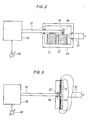
- the arrangement according to FIG. 2 shows a fiber optic voltage measuring device in which the measuring voltage U is connected via the measuring lines 32 to two stacks 51 and 52 of piezoelectric elements connected in parallel.
- the measuring voltage is connected to the stack with the opposite polarity, which means that a positive measuring voltage increases the height of one stack and decreases the height of the other stack and vice versa.
- the two-stack design reduces the influence of temperature while doubling the sensitivity.
- the end of the fiber 31 is fixed on one stack 51, and on the other a mirror 36 is fastened with a screen 35 which acts as an optical filter and which covers part of the fiber end. Due to the voltage U, the screen moves relative to the fiber and modulates the light in the fiber 31.
- the evaluation element 50 and the display device 48 are elements of the same type as in the arrangement according to FIG. 1.
- FIG. 3 shows a fiber-optic voltage measuring device in which the electro-optical conversion takes place with a piezoelectric high polymer.
- the measuring voltage U is connected via the measuring lines 32 with opposite polarity to two pieces of film 53 and 54 made of piezoelectric high polymer. Due to the different polarity, one piece of film is stretched while the other is contracted when a voltage is supplied via the measuring lines 32.
- the polymer film pieces 53 and 54 are connected to one another by a mirror 36, on the surface of which a screen 35 acting as an optical filter is seated. When the films are stretched or contracted, the mirror and the screen are shifted.
- the light in the fiber 31 is modulated by the movements of the screen and thus describes the measurement signal U.
- the evaluation element 50 and the display device 48 are elements of the same type as in the arrangement according to FIG. 1.
- FIG. 4 shows a fiber optic current measuring device, in which the measuring current 1 generates a magnetic field which acts on a piece 63 of magnetic material.
- the measuring current I flows through a coil 62 in which a part of said piece of magnetic material 63, for. B. soft iron, which is attached to springs 56 and carries a mirror 36.
- a screen 35 which acts as an optical filter, is attached between the mirror 36 and the end face of the fiber 31.
- the measuring current I flowing through the coil 62 exerts an attractive force on the material piece 63, which causes the springs 56 to deflect.
- the screen 35 is displaced in front of the end face of the fiber 31, whereby the light is rnodulated with the measuring current I.
- the evaluation element 50 and the display device 48 are elements of the same type as in the arrangement according to FIG. 1.
- FIG. 5 shows a current measuring device with an optical modulator, the effect of which is based on the thermal expansion of a tensioned wire through which current flows.
- the measuring current I flows through a wire 72, one end of which is clamped in place.
- the other end of the wire is fastened to a double spring 56 under pretension, which double spring carries a mirror 36 which is partially covered by a screen 35 which acts as an optical filter and is connected to the mirror.
- the screen 35 partially covers the end of the fiber 31.
- the fiber 31 is suspended in a wire 73 which is made of the same material as the wire 72 through which current flows. This compensates for temperature variations in the environment.
- the measuring current flowing through the wire 72 causes an extension of the wire and thus a displacement of the mirror 36 with the screen 35. This results in a modulation of the incoming light in the fiber 31, which is reflected to the evaluation element 50, in which it is as well the display device 48 is a member of the same type as in the arrangement according to FIG. 1.
- Figure 6 shows a fiber optic current measurement advises with an optical modulator, the effect of which is based on the fact that the current flowing through a wire heats and bends bimetal.
- the measuring current I flows through a wire 77 which is wound around two bimetal strips 75.
- the bimetallic strips 75 are firmly clamped at one end and carry a mirror 36 between their other ends. A part of the mirror surface is covered with a screen 35 which acts as an interference filter and which partially covers the end surface of the fiber 31.
- the measuring current I which flows through the wire 77, causes heating and thus bending of the bimetallic strips 75, the screen 35 moving in front of the end face of the fiber and modulating the light.
- the end of the fiber 31 is fastened between two bimetal strips 76 of the same type as the bimetal strips 75.
- the evaluation element 50 and the display device 48 are elements of the same type as in the arrangement according to FIG. 1.
- the invention can be varied in many ways within the scope of the general inventive idea disclosed. It is not limited to the exemplary embodiments shown.
- a “bimorphic” modulator or piezoelectric element in the sense of this application is understood to mean a piezoelectric crystal with two opposite polarization directions.
- a “multimorphic" piezoelectric element is one that consists, for example, of four crystals, two of which have opposite polarization directions and the other two have opposite polarization directions, which are 180 ° out of phase with the former.
Landscapes
- Physics & Mathematics (AREA)
- General Physics & Mathematics (AREA)
- Optical Transform (AREA)
- Arrangements For Transmission Of Measured Signals (AREA)
- Length Measuring Devices By Optical Means (AREA)
- Measuring Instrument Details And Bridges, And Automatic Balancing Devices (AREA)
Claims (7)
Applications Claiming Priority (2)
| Application Number | Priority Date | Filing Date | Title |
|---|---|---|---|
| SE7810643A SE414082B (sv) | 1978-10-12 | 1978-10-12 | Fiberoptiskt metdon |
| SE7810643 | 1978-10-12 |
Publications (2)
| Publication Number | Publication Date |
|---|---|
| EP0010221A1 EP0010221A1 (fr) | 1980-04-30 |
| EP0010221B1 true EP0010221B1 (fr) | 1983-02-09 |
Family
ID=20336072
Family Applications (1)
| Application Number | Title | Priority Date | Filing Date |
|---|---|---|---|
| EP19790103755 Expired EP0010221B1 (fr) | 1978-10-12 | 1979-10-02 | Appareil de mesure à fibres optiques |
Country Status (5)
| Country | Link |
|---|---|
| EP (1) | EP0010221B1 (fr) |
| JP (1) | JPS5552955A (fr) |
| CA (1) | CA1133066A (fr) |
| DE (1) | DE2964734D1 (fr) |
| SE (1) | SE414082B (fr) |
Cited By (1)
| Publication number | Priority date | Publication date | Assignee | Title |
|---|---|---|---|---|
| DE4114253A1 (de) * | 1991-05-02 | 1992-11-05 | Asea Brown Boveri | Faseroptischer sensor |
Families Citing this family (7)
| Publication number | Priority date | Publication date | Assignee | Title |
|---|---|---|---|---|
| US4379226A (en) * | 1981-02-02 | 1983-04-05 | Siemens Corporation | Method and sensor device for measuring a physical parameter utilizing an oscillatory, light modulation element |
| SE430437B (sv) * | 1982-03-15 | 1983-11-14 | Asea Ab | Fiberoptiskt metdon for metning av elektriska och magnetiska storheter |
| DE3504945A1 (de) * | 1984-05-24 | 1985-11-28 | MITEC Moderne Industrietechnik GmbH, 8012 Ottobrunn | Anordnung zum messen der elektrischen spannungsparameter eines hochspannungsleiters |
| DE3545257C2 (de) * | 1985-12-20 | 1994-01-05 | Deutsche Aerospace | Sensor zur Messung Elektromagnetischer Pulse |
| GB8716372D0 (en) * | 1987-07-10 | 1987-08-19 | Schlumberger Electronics Uk | Optical transducer system |
| US5235180A (en) * | 1992-03-05 | 1993-08-10 | General Scanning, Inc. | Rotary motor having an angular position transducer and galvanometer scanning system employing such motor |
| WO2008054879A1 (fr) | 2006-06-19 | 2008-05-08 | Gsi Group Corporation | Système de transducteur de position optique et procédé utilisant l'éclairage réfléchi |
Family Cites Families (5)
| Publication number | Priority date | Publication date | Assignee | Title |
|---|---|---|---|---|
| SE324463B (fr) * | 1968-03-27 | 1970-06-01 | Aga Ab | |
| DE1930111C3 (de) * | 1969-06-13 | 1975-02-20 | Vierling, Oskar, Prof. Dr.Phil.Habil., 8553 Ebermannstadt | Optische Vorrichtung zum Messen der Bewegung von gegeneinander bewegten Teilen |
| US3781092A (en) * | 1971-06-28 | 1973-12-25 | D Sussman | Monitoring system |
| DE2549497A1 (de) * | 1975-11-05 | 1977-05-12 | Franz Ummen | Verfahren zur uebertragung physikalischer messgroessen |
| CH639196A5 (de) * | 1977-11-23 | 1983-10-31 | Asea Ab | Messgeraet zum messen von physikalischen groessen mittels optischer mittel. |
-
1978
- 1978-10-12 SE SE7810643A patent/SE414082B/sv not_active IP Right Cessation
-
1979
- 1979-10-02 EP EP19790103755 patent/EP0010221B1/fr not_active Expired
- 1979-10-02 DE DE7979103755T patent/DE2964734D1/de not_active Expired
- 1979-10-09 JP JP12956779A patent/JPS5552955A/ja active Pending
- 1979-10-11 CA CA337,377A patent/CA1133066A/fr not_active Expired
Cited By (1)
| Publication number | Priority date | Publication date | Assignee | Title |
|---|---|---|---|---|
| DE4114253A1 (de) * | 1991-05-02 | 1992-11-05 | Asea Brown Boveri | Faseroptischer sensor |
Also Published As
| Publication number | Publication date |
|---|---|
| JPS5552955A (en) | 1980-04-17 |
| SE7810643L (sv) | 1980-04-13 |
| EP0010221A1 (fr) | 1980-04-30 |
| DE2964734D1 (en) | 1983-03-17 |
| CA1133066A (fr) | 1982-10-05 |
| SE414082B (sv) | 1980-07-07 |
Similar Documents
| Publication | Publication Date | Title |
|---|---|---|
| DE2945019C2 (fr) | ||
| EP0445362B1 (fr) | Dispositif de mesure d'une induction magnétique | |
| EP0011110B1 (fr) | Dispositif pour la mesure électro-optique de la tension | |
| EP0433824B1 (fr) | Capteur fibre-optique | |
| DE3609507C2 (de) | Faseroptisches Interferometer | |
| DE69328825T2 (de) | Elektrische Strommessung | |
| EP0010221B1 (fr) | Appareil de mesure à fibres optiques | |
| DE2806777C2 (fr) | ||
| WO2009037271A1 (fr) | Capteur à fibres optiques pour mesurer les déformations sur les éoliennes | |
| US4547729A (en) | Optical fiber measuring devices | |
| WO2016112993A1 (fr) | Dispositif de mesure optoélectrique et procédé de mesure d'un courant electrique | |
| DE2541072C3 (de) | Magnetooptischer Meßwandler zur Herstellung von Hochspannungsströmen | |
| DE1955403C3 (de) | Digitale Meßeinrichtung für Ströme in Hochspannungsleitern | |
| DE3504945A1 (de) | Anordnung zum messen der elektrischen spannungsparameter eines hochspannungsleiters | |
| DE69627656T2 (de) | Hochspannungsmessanordnung | |
| DE102016009936A1 (de) | LIDAR-System mit beweglicher Lichtfaser | |
| DE3726411A1 (de) | Faseroptischer magnetfeldsensor | |
| EP0854354A1 (fr) | Méthode pour compenser l'influence de la température sur les signaux mesurés par un capteur à fibre optique | |
| DE3031961C2 (de) | Interferometrische Einrichtung zur Messung physikalischer Größen | |
| DE3039235A1 (de) | "druckempfindlicher, faseroptischer sensor" | |
| DE2130047C3 (de) | Meßeinrichtung für Ströme | |
| WO1999008120A1 (fr) | Procede pour mesurer un champ magnetique et installation pour la mise en oeuvre dudit procede | |
| CH686744A5 (de) | Faseroptischer Stromsensor. | |
| DE3431769A1 (de) | Faseroptischer stromsensor | |
| DE584850C (de) | Einrichtung zur Ermittlung oder zum Ausgleich des Stellungsunterschiedes zweier raeumlich getrennter Wellen |
Legal Events
| Date | Code | Title | Description |
|---|---|---|---|
| PUAI | Public reference made under article 153(3) epc to a published international application that has entered the european phase |
Free format text: ORIGINAL CODE: 0009012 |
|
| AK | Designated contracting states |
Designated state(s): CH DE FR GB IT |
|
| 17P | Request for examination filed | ||
| ITF | It: translation for a ep patent filed | ||
| GRAA | (expected) grant |
Free format text: ORIGINAL CODE: 0009210 |
|
| AK | Designated contracting states |
Designated state(s): CH DE FR GB IT |
|
| REF | Corresponds to: |
Ref document number: 2964734 Country of ref document: DE Date of ref document: 19830317 |
|
| ET | Fr: translation filed | ||
| PLBE | No opposition filed within time limit |
Free format text: ORIGINAL CODE: 0009261 |
|
| STAA | Information on the status of an ep patent application or granted ep patent |
Free format text: STATUS: NO OPPOSITION FILED WITHIN TIME LIMIT |
|
| 26N | No opposition filed | ||
| PGFP | Annual fee paid to national office [announced via postgrant information from national office to epo] |
Ref country code: FR Payment date: 19840823 Year of fee payment: 6 |
|
| PGFP | Annual fee paid to national office [announced via postgrant information from national office to epo] |
Ref country code: CH Payment date: 19841025 Year of fee payment: 6 |
|
| PGFP | Annual fee paid to national office [announced via postgrant information from national office to epo] |
Ref country code: DE Payment date: 19841116 Year of fee payment: 6 |
|
| PG25 | Lapsed in a contracting state [announced via postgrant information from national office to epo] |
Ref country code: CH Effective date: 19871031 |
|
| GBPC | Gb: european patent ceased through non-payment of renewal fee | ||
| PG25 | Lapsed in a contracting state [announced via postgrant information from national office to epo] |
Ref country code: FR Free format text: LAPSE BECAUSE OF NON-PAYMENT OF DUE FEES Effective date: 19880630 |
|
| REG | Reference to a national code |
Ref country code: CH Ref legal event code: PL |
|
| PG25 | Lapsed in a contracting state [announced via postgrant information from national office to epo] |
Ref country code: DE Effective date: 19880701 |
|
| REG | Reference to a national code |
Ref country code: FR Ref legal event code: ST |
|
| PG25 | Lapsed in a contracting state [announced via postgrant information from national office to epo] |
Ref country code: GB Effective date: 19881118 |