EP0010240A1 - Thermomètre médical - Google Patents
Thermomètre médical Download PDFInfo
- Publication number
- EP0010240A1 EP0010240A1 EP79103824A EP79103824A EP0010240A1 EP 0010240 A1 EP0010240 A1 EP 0010240A1 EP 79103824 A EP79103824 A EP 79103824A EP 79103824 A EP79103824 A EP 79103824A EP 0010240 A1 EP0010240 A1 EP 0010240A1
- Authority
- EP
- European Patent Office
- Prior art keywords
- clinical thermometer
- engine
- display unit
- component
- electrical circuit
- Prior art date
- Legal status (The legal status is an assumption and is not a legal conclusion. Google has not performed a legal analysis and makes no representation as to the accuracy of the status listed.)
- Withdrawn
Links
- 230000001419 dependent effect Effects 0.000 claims abstract description 3
- 238000005259 measurement Methods 0.000 claims description 8
- 230000001960 triggered effect Effects 0.000 claims description 2
- 239000004575 stone Substances 0.000 description 11
- 239000004570 mortar (masonry) Substances 0.000 description 9
- 238000009413 insulation Methods 0.000 description 4
- 210000001503 joint Anatomy 0.000 description 4
- 238000004519 manufacturing process Methods 0.000 description 4
- QSHDDOUJBYECFT-UHFFFAOYSA-N mercury Chemical compound [Hg] QSHDDOUJBYECFT-UHFFFAOYSA-N 0.000 description 3
- 229910052753 mercury Inorganic materials 0.000 description 3
- 230000000694 effects Effects 0.000 description 2
- 238000000034 method Methods 0.000 description 2
- 238000003801 milling Methods 0.000 description 2
- 239000011324 bead Substances 0.000 description 1
- 239000011449 brick Substances 0.000 description 1
- 238000010586 diagram Methods 0.000 description 1
- 238000004146 energy storage Methods 0.000 description 1
- 238000011156 evaluation Methods 0.000 description 1
- 238000001125 extrusion Methods 0.000 description 1
- 230000010354 integration Effects 0.000 description 1
- 239000000463 material Substances 0.000 description 1
Images
Classifications
-
- G—PHYSICS
- G01—MEASURING; TESTING
- G01K—MEASURING TEMPERATURE; MEASURING QUANTITY OF HEAT; THERMALLY-SENSITIVE ELEMENTS NOT OTHERWISE PROVIDED FOR
- G01K7/00—Measuring temperature based on the use of electric or magnetic elements directly sensitive to heat ; Power supply therefor, e.g. using thermoelectric elements
- G01K7/16—Measuring temperature based on the use of electric or magnetic elements directly sensitive to heat ; Power supply therefor, e.g. using thermoelectric elements using resistive elements
- G01K7/22—Measuring temperature based on the use of electric or magnetic elements directly sensitive to heat ; Power supply therefor, e.g. using thermoelectric elements using resistive elements the element being a non-linear resistance, e.g. thermistor
- G01K7/24—Measuring temperature based on the use of electric or magnetic elements directly sensitive to heat ; Power supply therefor, e.g. using thermoelectric elements using resistive elements the element being a non-linear resistance, e.g. thermistor in a specially-adapted circuit, e.g. bridge circuit
-
- G—PHYSICS
- G01—MEASURING; TESTING
- G01K—MEASURING TEMPERATURE; MEASURING QUANTITY OF HEAT; THERMALLY-SENSITIVE ELEMENTS NOT OTHERWISE PROVIDED FOR
- G01K13/00—Thermometers specially adapted for specific purposes
- G01K13/20—Clinical contact thermometers for use with humans or animals
-
- G—PHYSICS
- G01—MEASURING; TESTING
- G01R—MEASURING ELECTRIC VARIABLES; MEASURING MAGNETIC VARIABLES
- G01R17/00—Measuring arrangements involving comparison with a reference value, e.g. bridge
- G01R17/02—Arrangements in which the value to be measured is automatically compared with a reference value
Definitions
- the invention relates to a clinical thermometer with a mechanically changeable electrical component and a display unit connected to it and with an electrical circuit for comparing signals of the mechanically changeable component with the signals of a temperature-dependent component and for generating control signals.
- thermometers have already been described (US Pat. No. 3,469,449) in which the voltage drop across a mechanically moved potentiometer is compared with the voltage drop across a resistor of a temperature-sensitive component and the measured temperature can be read off on a scale in the adjustment position.
- thermometer Compared to fully electronic clinical thermometers, such a thermometer has the advantage that false indications due to normal changes (e.g. drifting) of the electronic components are avoided because there is mechanically a clear reference value.
- thermometers are relatively complicated to use because a manual comparison of the two voltage signals is necessary. If a motor drive is used for this, there is the disadvantage that the motor drive consumes a relatively large amount of energy which is drawn from batteries in the case of mains-independent devices and which therefore consume very quickly.
- the invention is therefore the object of a 7-8uriab- hsseni g it to create thermometer, manages the stored with little electric power.
- thermometer characterized in that the display instrument with a biasable and releasable mechanical engine is connected and a B ewegung is provided sunterbrech un gs adopted that at Adjustment to a control signal of the electrical circuit interrupts the assignment of the display unit.
- a spirally biased spring is preferably used for the engine.
- the (previous) mercury clinical thermometers one was used to shaking the mercury column back to a starting position before taking a measurement. This is replaced in a device of the invention in that the engine is preloaded by hand before a measurement. The engine can then be triggered and runs until the movement of the display unit is interrupted by a movement interruption device when comparing to a control signal from the electrical comparison circuit.
- connection of the engine can be decoupled electromechanically from a counter used as a display unit, so that the moving counter stops at the moment in which the adjustment position is reached.
- Another advantageous embodiment of the invention is seen in the fact that the engine is designed so that at the same time sufficient electrical energy is supplied for the circuit.
- a dynamo can be connected to the engine.
- a re-calibration of the device of the invention is therefore practically not necessary because a rigid mechanical connection between the counter and the drive can be established in the range of the usual manufacturing tolerances, which does not change over a long period of time.
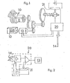
- FIG. 1 shows a drive system 10 for a clinical thermometer which is similar to a clockwork mechanism and is equipped with gearwheels which form a rigid connection with a predetermined step-up ratio between the potentiometer 21 forming the mechanically changeable electrical component and a counter 12.
- the counter 12 and the potentiometer 21 are moved together by a drive which receives an angular momentum from an engine 10, which results from the tensioning forces of a spiral leaf spring 11 with which the engine can be pretensioned.
- an analog display can also be provided, as indicated by way of example in the engine 10.
- a suitable brake is preferably installed in the gear train in such a way that a uniform rotational speed of the gear wheels is achieved with different strengths of pre-tension (torques) of the spirally wound leaf spring during a measurement.
- the components of this circuit can be mounted on the same surface on which the potentiometer 21 is arranged and from the connections to the sensor 10, e.g. an NTC resistor, go out ..
- the voltage applied to it changes due to the movement of the grinder of the potentiometer 21.
- the electrical circuit compares this voltage with that of the sensor 14 and gives a control signal to the movement interruption device 13 during adjustment. This stops the movement of the counter 12, so that after the measurement a counter reading remains which corresponds to the measured temperature value. If it is not sufficient that a possibly measurable overrun error due to inertia of the stop device is eliminated, then a double arrangement (not shown) of the engine and the drive is provided, which runs in the opposite direction of rotation and supplies two temperature limit values, the mean value of which is free of overrun errors.
- thermometer When the engine 10 is coupled to a power-generating component, for example a dynamo, it is also possible to create a clinical thermometer which can be operated entirely without electrical energy storage, e.g. Battery, because the energy for the electrical circuit 20 is then supplied by the drive.
- a power-generating component for example a dynamo
- electrical energy storage e.g. Battery
- the engine will be re-biased for each measurement.
- the counter 12 is set to a zero position during pretensioning, so that the clinical thermometer is to be handled like a mercury thermometer (which must also be brought mechanically to an initial position before each measurement).
- thermometer of the invention provides fast and accurate values.
- the invention also has the advantage that a mechanical counter can be used which stores the last measured temperature value for a long time without the supply of energy.
- thermometer does not correspond to reality, but are only intended to better emphasize what is essential to the invention.
- relatively small drives with a spring drive are provided, roughly on the order of the variable component to be used.
- Any bridge circuit that provides sufficiently precise comparison values such as the circuit 20 shown in FIG. 2 is of course suitable for the evaluation itself.
- the invention can also be extended to other temperature measuring devices which, as far as possible, do without a battery and are intended to provide sufficiently precise measured values in a narrow measuring range.
- the assembly gaps shown in FIGS. 1 to 4 can be produced on normal production machines for hollow blocks, the horizontal cutout 1 being produced by a mold core and the cutout 2 by pulling a sword.
- the core and the sword are slightly conical towards the center of the stone in accordance with the shape of the recesses described.
- the beads 3 mentioned can also be formed.
- the described arrangement of the recesses 1, 2 or the continuous insulating plates 4 also allows the use of stone production machines which, e.g. working in the brick industry in the strand process.
- the assembly block can be produced from a perforated stone material on an extrusion press, as shown in FIG. 8, the holes distributed over the entire stone cross-section ensuring even better thermal insulation, since the "cold flow" is further dissipated or interrupted.
- a mortar bed 6 can be pressed in and shaken during production with a complaint plate.
- the webs 7 remaining here can first be produced and produced to a height exceeding the desired stone height.
- After the assembly block has hardened, it can be machined plane-parallel with a special milling machine (e.g. according to DE-PS 1 427 712) and milled by a few millimeters.
- the assembly blocks are preferably produced without milling in the manner explained in more detail below with reference to FIGS. 9-13.
- the invention can also be applied to assembly blocks which are produced in the region 10 without extremely precise height tolerances of the webs 7 and the support surfaces. Stone height tolerances are then compensated by applying the appropriate thickness of bedding mortar, which, however, requires the use of a cord and spirit level for each layer laid.
- the special insulating effect by the plates 4 remains essentially in this case; only in the area of the bed joints could smaller mortar areas become visible due to the stone height deviations.
- the noise recess 11 also serves to accommodate mortar that may have been filled in too much, i.e. of the mortar bed 6.
- the assembly block at the four corners in the butt joints receives recesses 12 for receiving the butt joint mortar. The depth of these recesses 12 is such that superfluous bedding mortar can escape from the mortar bed 6 downwards.
- FIG. 4 shows an assembly block which, in addition to the features already described, has a plurality of separating grooves 13.
- the separating grooves facilitate sawing or hitting the block on the building if special stones are required, e.g. those with vertical slots 19 according to FIG. 7 or stones for wall connections according to FIGS. 5 and 6.
- special stones e.g. those with vertical slots 19 according to FIG. 7 or stones for wall connections according to FIGS. 5 and 6.
- a piece of insulating plate 14 which has been sawn out can be laterally reinserted, so that the thermal insulation is not interrupted.
- the insulating plates 4 according to FIGS. 3 and 4 can be moved horizontally according to the needs of the building, as indicated by the arrow 15. This is in contrast to known assembly blocks, which have crossbars in their recesses for holding the outer stone shell and thereby hold the insulating inserts, and to blocks whose insulating inserts consist of fillings which are not readily removable.
- the mounting blocks described here they can e.g. when erecting a wall with a non-standard length, be pulled sideways in such a way that there are greater distances between the individual blocks, as shown at 16 in FIG. In this case, too, both insulating plates 4 are pulled forward so that they engage in the next block and thus seal the butt joint with a high thermal insulation effect.
- Another possibility is to prefer the insulating plate 4 at the end of the wall or at the wall opening for a window or a door so that it provides a seal and simultaneous insulation e.g. the window or door frame ensures, as shown at 17 in FIG.
Landscapes
- Physics & Mathematics (AREA)
- General Physics & Mathematics (AREA)
- Nonlinear Science (AREA)
- Measuring And Recording Apparatus For Diagnosis (AREA)
- Measuring Temperature Or Quantity Of Heat (AREA)
Applications Claiming Priority (2)
| Application Number | Priority Date | Filing Date | Title |
|---|---|---|---|
| DE19782844416 DE2844416A1 (de) | 1978-10-12 | 1978-10-12 | Fieberthermometer |
| DE2844416 | 1978-10-12 |
Publications (1)
| Publication Number | Publication Date |
|---|---|
| EP0010240A1 true EP0010240A1 (fr) | 1980-04-30 |
Family
ID=6051981
Family Applications (1)
| Application Number | Title | Priority Date | Filing Date |
|---|---|---|---|
| EP79103824A Withdrawn EP0010240A1 (fr) | 1978-10-12 | 1979-10-06 | Thermomètre médical |
Country Status (2)
| Country | Link |
|---|---|
| EP (1) | EP0010240A1 (fr) |
| DE (1) | DE2844416A1 (fr) |
Citations (7)
| Publication number | Priority date | Publication date | Assignee | Title |
|---|---|---|---|---|
| US3545273A (en) * | 1968-06-13 | 1970-12-08 | Gen Instrument Corp | Electronic thermometer |
| CH501905A (fr) * | 1968-08-09 | 1971-01-15 | Test Sa D Etudes Tech | Thermomètre médical portatif |
| US3604266A (en) * | 1969-06-05 | 1971-09-14 | Computer Diode Corp | Temperature measuring apparatus |
| FR2206503A1 (fr) * | 1972-11-10 | 1974-06-07 | Test Sa | |
| DE2532610A1 (de) * | 1974-12-16 | 1976-07-01 | Huerlimann Heinz Dipl El Ing | Elektrischer fieberthermometer |
| US4117723A (en) * | 1976-10-26 | 1978-10-03 | Rudolph Maravich | Electronic thermometer |
| DE2724930A1 (de) * | 1977-06-02 | 1978-12-14 | Gross Hagen | Elektronisches thermometer |
-
1978
- 1978-10-12 DE DE19782844416 patent/DE2844416A1/de not_active Withdrawn
-
1979
- 1979-10-06 EP EP79103824A patent/EP0010240A1/fr not_active Withdrawn
Patent Citations (7)
| Publication number | Priority date | Publication date | Assignee | Title |
|---|---|---|---|---|
| US3545273A (en) * | 1968-06-13 | 1970-12-08 | Gen Instrument Corp | Electronic thermometer |
| CH501905A (fr) * | 1968-08-09 | 1971-01-15 | Test Sa D Etudes Tech | Thermomètre médical portatif |
| US3604266A (en) * | 1969-06-05 | 1971-09-14 | Computer Diode Corp | Temperature measuring apparatus |
| FR2206503A1 (fr) * | 1972-11-10 | 1974-06-07 | Test Sa | |
| DE2532610A1 (de) * | 1974-12-16 | 1976-07-01 | Huerlimann Heinz Dipl El Ing | Elektrischer fieberthermometer |
| US4117723A (en) * | 1976-10-26 | 1978-10-03 | Rudolph Maravich | Electronic thermometer |
| DE2724930A1 (de) * | 1977-06-02 | 1978-12-14 | Gross Hagen | Elektronisches thermometer |
Also Published As
| Publication number | Publication date |
|---|---|
| DE2844416A1 (de) | 1980-04-30 |
Similar Documents
| Publication | Publication Date | Title |
|---|---|---|
| DE19581468B4 (de) | Drehmomentwinkelschlüssel | |
| DE3784360T2 (de) | Kapazitanztransduktor fuer positionsmessung. | |
| DE3625795C2 (fr) | ||
| DE3417858A1 (de) | Winkelgeschwindigkeits-fuehlsystem | |
| EP0266713B1 (fr) | Dispositif pour mesurer des distances à partir d'une pièce d'oeuvre et pied à coulisse pourvu de mesure digitale de ces distances | |
| DE1282986B (de) | Vorrichtung zur Bestimmung der Fluglage und Flughoehe eines Flugkoerpers | |
| DE2413997B2 (de) | Bügelmeßschraube | |
| DE1808327A1 (de) | Rollenpruefstand fuer Motorfahrzeuge | |
| DE2255093A1 (de) | Messvorrichtung zum pruefen und/oder richten der querneigung von gleisen | |
| DE3418407A1 (de) | Kraftmesser, der mit elastischen oberflaechenwellen arbeitet | |
| EP0010240A1 (fr) | Thermomètre médical | |
| EP0402320A1 (fr) | Transducteur pour mesurer des forces et méthode de fabrication de ce transducteur | |
| DE3733575A1 (de) | Anzeigeelement | |
| DE68902712T2 (de) | Uhr mit einer exzentrischen anzeigeeinheit. | |
| DE1473415A1 (de) | Verfahren und Vorrichtung zum Aufzeichnen der von Kraftfahrzeugen bei ihrer Erprobung zum Durchfahren vorbestimmter Probestrecken benoetigten Zeiten | |
| EP2858731A1 (fr) | Inclinomètre numérique | |
| EP0406222A2 (fr) | Panneau d'affichage | |
| DE102024128330B3 (de) | Turmuhr und Verfahren zu deren Betrieb | |
| DE69001106T2 (de) | Schaltung zur Verarbeitung von Signalen, abgegeben von zwei in Differenzbetrieb arbeitenden Sensoren, die eine physikalische Grösse messen. | |
| DE3100941C2 (de) | Vorrichtung zur elektrischen Verbrauchsermittlung einzelner Wärmeverbraucher die von einer Wärmequelle versorgt werden | |
| DE19824711B4 (de) | Vorrichtung zum Messen von Fußkreisdruchmessern an Innenverzahnungen mit ungeraden Zähnezahlen | |
| DE2349567C3 (de) | Längenmeßgerät | |
| DE1683815C3 (de) | Vorrichtung zum Herstellen einer Folge von Bauelementen aus Beton o.dgl | |
| DE2622311C3 (de) | Steuereinrichtung mit Schwungradeigenschaften | |
| DE2115885A1 (de) | Zeitbasis Schwingungsemrichtung |
Legal Events
| Date | Code | Title | Description |
|---|---|---|---|
| PUAI | Public reference made under article 153(3) epc to a published international application that has entered the european phase |
Free format text: ORIGINAL CODE: 0009012 |
|
| AK | Designated contracting states |
Designated state(s): AT BE CH DE FR GB IT LU NL SE |
|
| STAA | Information on the status of an ep patent application or granted ep patent |
Free format text: STATUS: THE APPLICATION IS DEEMED TO BE WITHDRAWN |
|
| 18D | Application deemed to be withdrawn |
Effective date: 19810223 |
|
| RIN1 | Information on inventor provided before grant (corrected) |
Inventor name: REBBE, KLAUS Inventor name: THIERY, JOACHIM, DR. |