EP0010260B1 - Serre-joints - Google Patents
Serre-joints Download PDFInfo
- Publication number
- EP0010260B1 EP0010260B1 EP79103892A EP79103892A EP0010260B1 EP 0010260 B1 EP0010260 B1 EP 0010260B1 EP 79103892 A EP79103892 A EP 79103892A EP 79103892 A EP79103892 A EP 79103892A EP 0010260 B1 EP0010260 B1 EP 0010260B1
- Authority
- EP
- European Patent Office
- Prior art keywords
- slide rail
- screw clamp
- bearing member
- clamping
- bracket
- Prior art date
- Legal status (The legal status is an assumption and is not a legal conclusion. Google has not performed a legal analysis and makes no representation as to the accuracy of the status listed.)
- Expired
Links
Images
Classifications
-
- B—PERFORMING OPERATIONS; TRANSPORTING
- B25—HAND TOOLS; PORTABLE POWER-DRIVEN TOOLS; MANIPULATORS
- B25B—TOOLS OR BENCH DEVICES NOT OTHERWISE PROVIDED FOR, FOR FASTENING, CONNECTING, DISENGAGING, OR HOLDING
- B25B5/00—Clamps
- B25B5/06—Arrangements for positively actuating jaws
- B25B5/10—Arrangements for positively actuating jaws using screws
- B25B5/102—Arrangements for positively actuating jaws using screws with at least one jaw sliding along a bar
-
- B—PERFORMING OPERATIONS; TRANSPORTING
- B25—HAND TOOLS; PORTABLE POWER-DRIVEN TOOLS; MANIPULATORS
- B25B—TOOLS OR BENCH DEVICES NOT OTHERWISE PROVIDED FOR, FOR FASTENING, CONNECTING, DISENGAGING, OR HOLDING
- B25B1/00—Vices
- B25B1/24—Details, e.g. jaws of special shape, slideways
- B25B1/2489—Slideways
-
- B—PERFORMING OPERATIONS; TRANSPORTING
- B25—HAND TOOLS; PORTABLE POWER-DRIVEN TOOLS; MANIPULATORS
- B25B—TOOLS OR BENCH DEVICES NOT OTHERWISE PROVIDED FOR, FOR FASTENING, CONNECTING, DISENGAGING, OR HOLDING
- B25B5/00—Clamps
- B25B5/16—Details, e.g. jaws, jaw attachments
- B25B5/163—Jaws or jaw attachments
-
- B—PERFORMING OPERATIONS; TRANSPORTING
- B25—HAND TOOLS; PORTABLE POWER-DRIVEN TOOLS; MANIPULATORS
- B25B—TOOLS OR BENCH DEVICES NOT OTHERWISE PROVIDED FOR, FOR FASTENING, CONNECTING, DISENGAGING, OR HOLDING
- B25B5/00—Clamps
- B25B5/16—Details, e.g. jaws, jaw attachments
- B25B5/166—Slideways; Guiding and/or blocking means for jaws thereon
Definitions
- the invention relates to a screw clamp with a slide rail, which carries a fixed bracket having a first clamping surface and on which a support piece is arranged so as to be longitudinally displaceable with a recess, which has a second clamping surface which is essentially parallel to the first clamping surface, and with a part designed as a separate part from the support piece
- Support bracket which is arranged to be longitudinally displaceable with a guide opening on the slide rail and can be fixed relative to it, in particular by tilting, and with a threaded spindle, which can be placed against the side of the support piece facing away from the fixed bracket and is held in a threaded bore of the support bracket, for clamping a workpiece between the first and the second Clamping surface.
- the support piece is designed as a relatively thin plate which is supported with its end facing away from the slide rail via a type of ball joint on the threaded spindle and directly next to the slide rail on a projection of the support bracket .
- the support bracket bends, but the clamping surfaces of the screw clamp can fit snugly against the workpiece surfaces and consequently remain parallel to one another.
- the recess of the support piece is designed as a simple opening in the plate mentioned, which cannot take over the function of a parallel guide.
- the invention had for its object to provide a screw clamp of the type mentioned, in which a certain and preferably a right angle between the second clamping surface and the slide rail can always be guaranteed.
- this object is achieved in that the support piece has at least two alignment members which, viewed in the longitudinal direction of the slide rail, are arranged at a distance from one another and are each adjacent to one of the longitudinal edges of the slide rail and are designed such that they can be pressed against these longitudinal edges when clamping a workpiece , but can be moved along these longitudinal edges.
- the alignment members thus ensure a predetermined alignment of the support piece relative to the slide rail, predetermined by their arrangement in the support piece, even while tightening the threaded spindle and in the case of workpieces whose surfaces to be tensioned are not parallel to one another, since it is ensured that the support piece also remains in place of the clamping process in the direction of the fixed bracket and since the support piece is not supported except on the threaded spindle on the support bracket, which bends when tilted on the slide rail.
- the screw clamp according to the invention it is therefore always possible to clamp at right angles with respect to the slide rail, and the precise guidance of the support piece on the slide rail required for this purpose has been made technically particularly simple and reliable.
- the alignment members each be assigned a further alignment member which can be placed on the opposite longitudinal edge of the slide rail.
- the alignment members In order to be able to move the support piece along the slide rail as easily as possible despite exact guidance, it is also advisable to design the alignment members in a circular cylindrical cross section and to arrange them so that their axes extend transversely to the adjacent longitudinal edge of the slide rail. There is then only a line contact between the alignment members and the slide rail, which reduces the friction to a minimum. It is even more advantageous if the alignment members are formed by hollow cylindrical rollers which are mounted on cylindrical bearing pins held in the support piece.
- the screw clamp In order to give the support piece the necessary rigidity in the cheapest way, in a preferred embodiment of the screw clamp according to the invention it has a supporting body which is formed by a one-piece sheet metal stamped and bent part having two legs arranged in parallel spacing, between the legs of which the Slide rail extends through and the alignment members are arranged. In this case, it is also advisable to arrange the support body within a housing made of plastic which forms the flat, second clamping surface and which is closed at least at the front end of the support piece. Such a plastic housing can be produced cheaply and ensures an appealing and exact outer shape of the support piece.
- the legs of the support body are then rigidly connected to one another at least in an area between its front end and the slide rail by a connecting web, and the clamping surface of the plastic housing is partially slotted in the longitudinal direction and the latter is designed such that it relates to the Can slide the support body in its longitudinal direction, the slot being expanded over a region to form a recess which rests with its lateral edge parts on the flat sides of the slide rail.
- This construction enables a particularly simple assembly of the plastic housing, wherein the web connecting the two legs of the supporting body can also be used for anchoring the plastic housing, for which purpose this connecting web is overlapped laterally by approaches of the plastic housing.
- the plastic housing also takes over to a certain extent the function of guiding the support piece on the slide rail, in that the slot mentioned is widened over a certain area to form a recess that fits the slide rail. As a result, it is not necessary to use the legs of the supporting body for a guide on the slide rail that is stable against tilting about the longitudinal axis of the support piece.
- the hollow cylindrical rollers forming the alignment members are removably arranged on bearing pins, interchangeability of the alignment members is made possible on the one hand, and on the other hand, by removing the rollers, the support piece on the slide rail can also be arranged so that it can be tilted in order to be able to clamp workpieces on surfaces that are not parallel to one another.
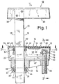
- a steel slide rail of the screw clamp is designated, at the upper end according to FIG.
- This fixed bracket is assigned a support piece, which is designated as a whole by 14 and is displaceably arranged on the slide rail.
- Fixed arm and support piece each have the longitudinal edges 16, 18 of the rail adjacent the clamping surfaces 20, 20 'or 22, 22', on the length of the clamping surfaces ', 22' is substantially smaller 20 than the length of the clamping surfaces 20, 22 .
- FIG. 24 designates a support bracket as a whole, which, according to FIG. 1, is provided on the side of the support piece 14 facing away from the fixed bracket and is displaceable on the slide rail 10 and can be locked by tilting.
- the support piece 14 has a support body 26 formed by a formed sheet-metal stamped part, which has two legs 28, 30 which are arranged at a parallel distance from one another and which are rigidly connected to one another by a connecting web 32.
- the slide rail extends in the rear area of the support piece approximately in the middle of the legs through the support body and its connecting web is located both at a distance from the front end of the legs 28, 30 and at a short distance from the slide rail 10.
- the guidance of the support piece 14 on the slide rail is designed such that its clamping surfaces 22, 22 'are essentially at right angles in every phase of an adjustment movement and when clamping a workpiece with respect to the slide rail.
- This can be accomplished by at least two alignment members located within the support body 26, i.e. are arranged between its legs 28, 30 such that they press against the longitudinal edges 16, 18 of the slide rails when clamping a workpiece.
- one of the alignment members 34 according to FIG. 1, in the upper region of the support body approximately between the slide rail and connecting web 32 and the other alignment member designated 36, viewed in the longitudinal direction of the slide rail 10, arranged at a distance therefrom and on the opposite one Long edge 8 of the slide rail would rest.
- a further alignment member 34 'or 36' is assigned to these alignment members in the same plane, but on the opposite longitudinal edge of the slide rail, all of which abut the longitudinal edges of the rails.
- the distance between the upper and the lower pair of alignment members is selected to be relatively large in order to achieve the most favorable conditions with regard to the required force absorption.
- the legs 28, 30 of the support body 26 in the region of the slide rail are each equipped with an extension 38, which extends downward according to FIG. 1, between which the alignment members 36, 36 'are held.
- the alignment members are formed, for example, by hollow cylindrical rollers 42 which are rotatably mounted on cylindrical bearing pins 44 held between the legs of the supporting body.
- the alignment members are formed, for example, by hollow cylindrical rollers 42 which are rotatably mounted on cylindrical bearing pins 44 held between the legs of the supporting body.
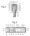
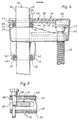
- the support body 26 is located within a plastic housing, which is designated as a whole by 46. This is U-shaped in cross section, its lateral legs 48, 50 covering the legs of the supporting body from the outside and also encompassing the lower leg edges with a thickened section 48 'or 50'.
- the connecting web 54 of the plastic housing connecting the lateral legs 48, 50 to one another forms the clamping surfaces 22, 22 'on its outside.
- the plastic housing has the maximum height of the support body legs 28, 30 and preferably covers the lower lugs 38, 40 of the legs 28, 30 of the support body on the outside thereof, so that the lugs 38, 40 are not in view.
- the plastic housing is closed at its front end by an end wall 60. It takes over the guidance of the support piece 14 in such a way that it is guided on the slide rail about its longitudinal axis in an essentially tilt-stable manner.
- an opening 62 provided in the connecting web 54 and penetrated by the slide rail assumes a guiding function, which is why it lies closely against the flat sides of the slide rail.
- this opening tapers to a slot 64 which is accessible from the front end of the plastic housing.
- this is to be pushed onto the support body from the front or right front end of the support body according to FIG. 1 until the end wall 60 comes into contact with the right end end of the legs 28, 30 according to FIG. 1.
- a threaded spindle 66 For clamping a workpiece between the fixed bracket and the support piece, a threaded spindle 66, which is guided in the bracket 24 at its front end and is rotatably held with a ball head 68 in a socket 70 of a pressure transmission piece 72.
- the pressure transmission piece consists, for example, of a shaped body made of steel, which is held by means of opposing retaining webs 74, 76 in slots 78 and 80 accessible from the front end of the supporting body legs 28, 30.
- 82 denotes support webs that extend in the direction of the pressure transmission piece and rest on its upper side, which are molded onto the connecting web 54 of the plastic housing 46.
- the support bracket 24 is displaceably guided between the two pairs of aligning members 34, 34 ', 36, 36' and its width is dimensioned such that it can engage between the legs of the plastic housing.
- Support bracket and support piece thus form a structural unit to a certain extent, the required reaction force when clamping a workpiece being generated solely by the support bracket, in which it wedges with its guide on the slide rail when the threaded spindle 66 is tightened.
- the distance between the two pairs of alignment members 34 to 36 can also be chosen only so large that the arrangement of the support bracket 24 below the lower pair of alignment members is to be provided on the slide rail.
- the parts 14 and 24 therefore run into one another to save space and support and cover one another.
- the support piece and support bracket can thus be inserted into the enveloping plastic housing 46 and are held in this in particular by the bearing pins 44.
- the bearing pins can e.g. be designed eccentrically, so that the rollers 42 can be lifted off the slide rail by twisting, in order to allow the support piece 14 to tilt and thus also to clamp workpieces with inclined contact surfaces.
- rollers 42 as alignment members also allows the production of a screw clamp in the simplest way, the support member of which adapts to inclined contact surfaces of workpieces if the arrangement of the rollers 42 on the bearing pin 44 is dispensed with during their assembly.
- the basic concept of the screw clamp construction according to the invention thus also allows the production of screw clamps which only clamp in parallel and which only adapt to inclined workpiece surfaces.
- the legs 28, 30 of the Support body 26 connecting connecting web 32 extends to the right front end of the support body according to FIG. 4 and thereby a particularly stable construction is achieved which enables workpieces to be reliably clamped between relatively narrow areas of the clamping surfaces of the fixed bracket and support piece which are adjacent to the flat sides of the slide rail 10.
- the slide rail can also serve as a workpiece system as well as a ruler.
- alignment members designated by 90 have a flat contact surface 92 and are axially displaceable but rotatable in the support piece 14, for example by a polygonal, in particular rectangular cross-sectional shape can be accomplished.
- the contact surface 92 is in frictional contact with the adjacent longitudinal edge of the slide rail 10, so that the clamping surface 22 of the support piece 14 is parallel to the clamping surface 20 of the fixed bracket 12 is aligned, while after the axial adjustment of the alignment members, according to FIG. 5 to the right, they come out of contact with the slide rail so that the support piece 14 can tip over in order to be able to clamp workpieces whose surfaces on the fixed bracket and support piece are not parallel to one another are.
Landscapes
- Engineering & Computer Science (AREA)
- Mechanical Engineering (AREA)
- Gripping Jigs, Holding Jigs, And Positioning Jigs (AREA)
- Clamps And Clips (AREA)
- Control Of Motors That Do Not Use Commutators (AREA)
- Surgical Instruments (AREA)
- Machine Tool Units (AREA)
Claims (16)
Priority Applications (1)
| Application Number | Priority Date | Filing Date | Title |
|---|---|---|---|
| AT79103892T ATE4632T1 (de) | 1978-10-14 | 1979-10-10 | Schraubzwinge. |
Applications Claiming Priority (2)
| Application Number | Priority Date | Filing Date | Title |
|---|---|---|---|
| DE19782844838 DE2844838A1 (de) | 1978-10-14 | 1978-10-14 | Schraubzwinge |
| DE2844838 | 1978-10-14 |
Publications (3)
| Publication Number | Publication Date |
|---|---|
| EP0010260A2 EP0010260A2 (fr) | 1980-04-30 |
| EP0010260A3 EP0010260A3 (en) | 1980-05-14 |
| EP0010260B1 true EP0010260B1 (fr) | 1983-04-27 |
Family
ID=6052208
Family Applications (1)
| Application Number | Title | Priority Date | Filing Date |
|---|---|---|---|
| EP79103892A Expired EP0010260B1 (fr) | 1978-10-14 | 1979-10-10 | Serre-joints |
Country Status (3)
| Country | Link |
|---|---|
| EP (1) | EP0010260B1 (fr) |
| AT (1) | ATE4632T1 (fr) |
| DE (2) | DE2844838A1 (fr) |
Cited By (3)
| Publication number | Priority date | Publication date | Assignee | Title |
|---|---|---|---|---|
| US6957808B2 (en) | 2001-11-13 | 2005-10-25 | Wmh Tool Group, Inc. | Apparatus for securing a workpiece |
| US7798478B2 (en) | 2004-02-23 | 2010-09-21 | Walter Meier (Manufacturing) Inc. | Parallel clamp and accessories therefor |
| DE10158005B4 (de) * | 2001-11-22 | 2016-05-19 | Bessey Tool Gmbh & Co. Kg | Bügelzwinge |
Families Citing this family (6)
| Publication number | Priority date | Publication date | Assignee | Title |
|---|---|---|---|---|
| DE3128023A1 (de) * | 1981-07-16 | 1983-02-03 | Bessey & Sohn Gmbh & Co, 7000 Stuttgart | "schraubzwinge" |
| DE3700955A1 (de) * | 1986-01-17 | 1987-07-23 | Bessey & Sohn | Beilageschiene |
| DE8615005U1 (de) * | 1986-06-04 | 1986-07-24 | Bessey & Sohn GmbH & Co, 7120 Bietigheim-Bissingen | Schraubzwinge |
| AUPN034394A0 (en) * | 1994-12-30 | 1995-01-27 | Matthews, Norman Leslie | Clamping device |
| DE19546048C2 (de) * | 1995-12-09 | 1999-07-08 | Gross & Froelich | Schraubzwinge |
| DE102007039841B3 (de) * | 2007-08-16 | 2008-09-18 | Bessey Tool Gmbh & Co. Kg | Zwinge und Verfahren zur Herstellung einer Zwinge |
Family Cites Families (2)
| Publication number | Priority date | Publication date | Assignee | Title |
|---|---|---|---|---|
| CH293210A (it) * | 1951-09-12 | 1953-09-15 | Uffireco S A | Morsetto a mano senza vite di serraggio. |
| GB1428381A (en) * | 1972-04-26 | 1976-03-17 | Harley A N | Clamping device |
-
1978
- 1978-10-14 DE DE19782844838 patent/DE2844838A1/de not_active Withdrawn
-
1979
- 1979-10-10 DE DE7979103892T patent/DE2965293D1/de not_active Expired
- 1979-10-10 AT AT79103892T patent/ATE4632T1/de not_active IP Right Cessation
- 1979-10-10 EP EP79103892A patent/EP0010260B1/fr not_active Expired
Cited By (4)
| Publication number | Priority date | Publication date | Assignee | Title |
|---|---|---|---|---|
| US6957808B2 (en) | 2001-11-13 | 2005-10-25 | Wmh Tool Group, Inc. | Apparatus for securing a workpiece |
| DE10158005B4 (de) * | 2001-11-22 | 2016-05-19 | Bessey Tool Gmbh & Co. Kg | Bügelzwinge |
| US7798478B2 (en) | 2004-02-23 | 2010-09-21 | Walter Meier (Manufacturing) Inc. | Parallel clamp and accessories therefor |
| US8282088B2 (en) | 2004-02-23 | 2012-10-09 | Walter Meier (Manufacturing) Inc. | Parallel clamp and accessories therefor |
Also Published As
| Publication number | Publication date |
|---|---|
| EP0010260A2 (fr) | 1980-04-30 |
| DE2965293D1 (en) | 1983-06-01 |
| EP0010260A3 (en) | 1980-05-14 |
| ATE4632T1 (de) | 1983-09-15 |
| DE2844838A1 (de) | 1980-04-24 |
Similar Documents
| Publication | Publication Date | Title |
|---|---|---|
| EP0229836B1 (fr) | Outil d'usinage | |
| EP2178678B1 (fr) | Serre-joint et procédé de fabrication d'un serre-joint | |
| DE4236049A1 (de) | C-förmige Zwinge | |
| CH657190A5 (de) | Klemmvorrichtung zum loesbaren verbinden zweier profilstuecke. | |
| DE2630763B2 (de) | Haltevorrichtung für teleskopartig ineinander verschiebbare Stangen mit ähnlichem Querschnitt | |
| DE1299196B (de) | Werkzeughalter | |
| DE102021128021B4 (de) | Rohrhalteclip | |
| DE2533019C2 (de) | Vorrichtung zur ausrichtbaren Halterung eines Lagers an einer ebenen Tragfläche | |
| CH659613A5 (de) | Befestigungskloben. | |
| DE29915435U1 (de) | Trägerklemme | |
| DE102015118505B4 (de) | Befestigungsvorrichtung | |
| EP0010260A2 (fr) | Serre-joints | |
| DE3871807T2 (de) | Scharnier. | |
| DE10212343A1 (de) | Schlittensystem | |
| AT520767B1 (de) | Anordnung aus einem Auflagesteg für einen Schubladenboden und einer Haltevorrichtung | |
| EP0107005A1 (fr) | Bride de fixation pour outils, en particulier pour outils de travail du sol | |
| DE3135881C1 (de) | Spannzwinge | |
| DE19909283A1 (de) | Verfahren zur Befestigung von Sitzschienen | |
| DE2613673A1 (de) | Spannvorrichtung | |
| DE102004041745A1 (de) | Gleitführungssystem | |
| CH651358A5 (de) | Vorrichtung zur befestigung eines laenglichen teils an einem maschinen- oder geraeteteil. | |
| EP0641940A2 (fr) | Dispositif de connexion pour pièces profilées | |
| DE4328107C1 (de) | Haltebacke für eine Rohrhalterung | |
| DE2748028C2 (de) | Schnellverstellzirkel | |
| DE1609301C3 (de) | Abdeckvorrichtung für Dehnungsfugen |
Legal Events
| Date | Code | Title | Description |
|---|---|---|---|
| PUAI | Public reference made under article 153(3) epc to a published international application that has entered the european phase |
Free format text: ORIGINAL CODE: 0009012 |
|
| PUAL | Search report despatched |
Free format text: ORIGINAL CODE: 0009013 |
|
| AK | Designated contracting states |
Designated state(s): AT CH DE FR IT NL SE |
|
| AK | Designated contracting states |
Designated state(s): AT CH DE FR IT NL SE |
|
| 17P | Request for examination filed | ||
| ITF | It: translation for a ep patent filed | ||
| GRAA | (expected) grant |
Free format text: ORIGINAL CODE: 0009210 |
|
| AK | Designated contracting states |
Designated state(s): AT CH DE FR IT NL SE |
|
| REF | Corresponds to: |
Ref document number: 3141 Country of ref document: AT Date of ref document: 19830515 Kind code of ref document: T |
|
| REF | Corresponds to: |
Ref document number: 2965293 Country of ref document: DE Date of ref document: 19830601 |
|
| ET | Fr: translation filed | ||
| PUAC | Information related to the publication of a b1 document modified or deleted |
Free format text: ORIGINAL CODE: 0009299EPPU |
|
| GRAA | (expected) grant |
Free format text: ORIGINAL CODE: 0009210 |
|
| DB1 | Publication of patent cancelled | ||
| AK | Designated contracting states |
Designated state(s): AT CH DE FR IT NL SE |
|
| PGFP | Annual fee paid to national office [announced via postgrant information from national office to epo] |
Ref country code: NL Payment date: 19830914 Year of fee payment: 5 |
|
| REF | Corresponds to: |
Ref document number: 4632 Country of ref document: AT Date of ref document: 19830915 Kind code of ref document: T |
|
| ET | Fr: translation filed | ||
| PLBE | No opposition filed within time limit |
Free format text: ORIGINAL CODE: 0009261 |
|
| STAA | Information on the status of an ep patent application or granted ep patent |
Free format text: STATUS: NO OPPOSITION FILED WITHIN TIME LIMIT |
|
| 26N | No opposition filed | ||
| PGFP | Annual fee paid to national office [announced via postgrant information from national office to epo] |
Ref country code: SE Payment date: 19841231 Year of fee payment: 6 |
|
| PG25 | Lapsed in a contracting state [announced via postgrant information from national office to epo] |
Ref country code: NL Effective date: 19850501 |
|
| NLV4 | Nl: lapsed or anulled due to non-payment of the annual fee | ||
| PG25 | Lapsed in a contracting state [announced via postgrant information from national office to epo] |
Ref country code: SE Effective date: 19851011 |
|
| ITTA | It: last paid annual fee | ||
| PGFP | Annual fee paid to national office [announced via postgrant information from national office to epo] |
Ref country code: AT Payment date: 19941006 Year of fee payment: 16 |
|
| PGFP | Annual fee paid to national office [announced via postgrant information from national office to epo] |
Ref country code: CH Payment date: 19941014 Year of fee payment: 16 |
|
| PGFP | Annual fee paid to national office [announced via postgrant information from national office to epo] |
Ref country code: FR Payment date: 19941018 Year of fee payment: 16 |
|
| EUG | Se: european patent has lapsed |
Ref document number: 79103892.0 Effective date: 19860730 |
|
| PG25 | Lapsed in a contracting state [announced via postgrant information from national office to epo] |
Ref country code: AT Effective date: 19951010 |
|
| PG25 | Lapsed in a contracting state [announced via postgrant information from national office to epo] |
Ref country code: CH Effective date: 19951031 |
|
| REG | Reference to a national code |
Ref country code: CH Ref legal event code: PL |
|
| PG25 | Lapsed in a contracting state [announced via postgrant information from national office to epo] |
Ref country code: FR Effective date: 19960628 |
|
| REG | Reference to a national code |
Ref country code: FR Ref legal event code: ST |
|
| PGFP | Annual fee paid to national office [announced via postgrant information from national office to epo] |
Ref country code: DE Payment date: 19971125 Year of fee payment: 19 |
|
| PG25 | Lapsed in a contracting state [announced via postgrant information from national office to epo] |
Ref country code: DE Free format text: LAPSE BECAUSE OF NON-PAYMENT OF DUE FEES Effective date: 19990803 |