EP0010266A1 - Dispositif d'expansion actionné par la pression d'un fluide pour mandrins expansibles pour la fixation de bobines de matériaux tels que papier, plastique, tissu ou similaire et mandrin expansible sur lequel de tels dispositifs sont appliqués - Google Patents
Dispositif d'expansion actionné par la pression d'un fluide pour mandrins expansibles pour la fixation de bobines de matériaux tels que papier, plastique, tissu ou similaire et mandrin expansible sur lequel de tels dispositifs sont appliqués Download PDFInfo
- Publication number
- EP0010266A1 EP0010266A1 EP79103930A EP79103930A EP0010266A1 EP 0010266 A1 EP0010266 A1 EP 0010266A1 EP 79103930 A EP79103930 A EP 79103930A EP 79103930 A EP79103930 A EP 79103930A EP 0010266 A1 EP0010266 A1 EP 0010266A1
- Authority
- EP
- European Patent Office
- Prior art keywords
- expansion
- bladder
- connector
- housing
- shaft
- Prior art date
- Legal status (The legal status is an assumption and is not a legal conclusion. Google has not performed a legal analysis and makes no representation as to the accuracy of the status listed.)
- Granted
Links
- 239000012530 fluid Substances 0.000 title claims abstract description 20
- 239000000463 material Substances 0.000 title claims description 7
- 239000004744 fabric Substances 0.000 title description 2
- 235000001674 Agaricus brunnescens Nutrition 0.000 claims description 5
- 238000007789 sealing Methods 0.000 claims description 5
- 230000015572 biosynthetic process Effects 0.000 claims description 4
- 229910000831 Steel Inorganic materials 0.000 claims description 3
- 239000010959 steel Substances 0.000 claims description 3
- 239000000853 adhesive Substances 0.000 claims description 2
- 230000001070 adhesive effect Effects 0.000 claims description 2
- 229910001234 light alloy Inorganic materials 0.000 claims 2
- 239000007787 solid Substances 0.000 claims 1
- 238000003780 insertion Methods 0.000 description 2
- 230000037431 insertion Effects 0.000 description 2
- 238000004519 manufacturing process Methods 0.000 description 2
- 239000002390 adhesive tape Substances 0.000 description 1
- XAGFODPZIPBFFR-UHFFFAOYSA-N aluminium Chemical compound [Al] XAGFODPZIPBFFR-UHFFFAOYSA-N 0.000 description 1
- 229910052782 aluminium Inorganic materials 0.000 description 1
- 238000010276 construction Methods 0.000 description 1
- 230000002950 deficient Effects 0.000 description 1
- 239000013013 elastic material Substances 0.000 description 1
- 238000003754 machining Methods 0.000 description 1
- 230000002459 sustained effect Effects 0.000 description 1
Images

Classifications
-
- B—PERFORMING OPERATIONS; TRANSPORTING
- B65—CONVEYING; PACKING; STORING; HANDLING THIN OR FILAMENTARY MATERIAL
- B65H—HANDLING THIN OR FILAMENTARY MATERIAL, e.g. SHEETS, WEBS, CABLES
- B65H75/00—Storing webs, tapes, or filamentary material, e.g. on reels
- B65H75/02—Cores, formers, supports, or holders for coiled, wound, or folded material, e.g. reels, spindles, bobbins, cop tubes, cans, mandrels or chucks
- B65H75/18—Constructional details
- B65H75/24—Constructional details adjustable in configuration, e.g. expansible
- B65H75/242—Expansible spindles, mandrels or chucks, e.g. for securing or releasing cores, holders or packages
- B65H75/243—Expansible spindles, mandrels or chucks, e.g. for securing or releasing cores, holders or packages actuated by use of a fluid
- B65H75/2437—Expansible spindles, mandrels or chucks, e.g. for securing or releasing cores, holders or packages actuated by use of a fluid comprising a fluid-pressure-actuated elastic member, e.g. a diaphragm or a pneumatic tube
-
- Y—GENERAL TAGGING OF NEW TECHNOLOGICAL DEVELOPMENTS; GENERAL TAGGING OF CROSS-SECTIONAL TECHNOLOGIES SPANNING OVER SEVERAL SECTIONS OF THE IPC; TECHNICAL SUBJECTS COVERED BY FORMER USPC CROSS-REFERENCE ART COLLECTIONS [XRACs] AND DIGESTS
- Y10—TECHNICAL SUBJECTS COVERED BY FORMER USPC
- Y10T—TECHNICAL SUBJECTS COVERED BY FORMER US CLASSIFICATION
- Y10T279/00—Chucks or sockets
- Y10T279/10—Expanding
- Y10T279/1021—Fluid-pressure actuator
- Y10T279/1024—Directly expanding jaws
Definitions
- the pxcesent invention concerns a fluid pressure actuated expansion device for a shaft equipped with such expansion devices designed for holding in place spools or reels of material in the form of sheets or the like, such spools being made with cores of cardboard, steel aluminum or any other material, or simply consisting of material wound around itself and an expansion shaft with such devices.
- one or several elastic bladders are fitted into T or dovetail splines machined on the shaft surface; this makes replacement of a bladder somewhat easier than in the preceding type of shaft, but still requires disasasmbly of all expanding elements or pins located above the bladders.
- the operation involved is substantially time-consuming and its outcome is unpredictable, as it is performed by the user of the shaft who is less experienced than the manufacturer of the same.
- the machining of T or dovetail splines on the shaft surface is a considerably difficult and time-consuming task, which contributes to the high cost of manufacturing these shafts.
- An object of this invention is the problem solution which makes it possible to eliminate the above said drawbacks inherentin the above outlined construction and thus reduce the.. cost of manufacturing the shafts, as well as to permit a much quicker replacement of defective elements.
- a fluid pressure actuated expansion device for expansion shafts, the device including an expandable pressing shoe member having an operative body portion and a shoulder projecting from said operative body portion for delimiting the expansion stroke thereof, an inflatable tubular bladder member cooperating with said shoe member for actuating the expansion movement thereof and duct and valve means connectable with pressure fluid ducts for conducting and controlling the pressure fluid flow into and out of said bladder member t characterized in that the device further comprises a channel section shaped housing member for containing therein said shoe member and said bladder member, said housing member having an open longitudinal side thereof and a border delimiting an opening of said open side, said border having at least along a partial length thereof an inwardly projecting flange formation restricting the width of said opening, said restricted width allowing passage therethrough of said operative body portion of the shoe member and said flange formation defining together with said shoulder a stop preventing the passage of said shoulder through said restricted width opening and delimiting thereby the expansion stroke of
- the present invention provides essentially that both the elastic bladders and the expanding shoes located abpve them be fittcd into a separately built channel section shaped housing member, separate from the shaft body, so as to obtain an integral or self-contained unit or component containing a bladder, expanding shoes and a connector for supplying the fluid under pressure, such as compressed air.
- One or more of said components are subsequently fastened to the shaft surface into U-shaped, easy-to-cut slots machined in the shaft body, by means of screws and/or adhesive elements.
- Said components can all be simultaneously inflated and deflated through a hole with check valve drilled into the shaft body and communicating with the previously built expanding elements secured to the shaft body.
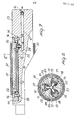
- the flanges 13a at the ends of the channel section shaped housing 13 in Figure 5 are removed in order to allow insertion of closing end blocks 14; also, holes 15 are drilled through the blocks 14 and the housing 13 at the ends thereof to permit passage of screws 16.
- Hole 17 provided in the housing member 13 is designed for passage of the mushroom-shaped short feed pipe connector 18.
- On the bottom of housing member 13 is laid a bladder 19 with the mushroom head of the connector 18 inserted into a hole made in the bladder's wall.
- the stem 18a of the connector 18 is introduced into hole 17 and secured to the housing member 13 by means of locknut 20, pressing the bladder between the head of connector 18 and the bottom of the housing member 13 and positively sealing the hole in the bladder.
- a pin valve (not shown) of the type disclosed in the above mentioned Applicant's U.S. Patent can be provided in the connector 18 in order to prevent that in case of failure of one bladder, the other bladders are deflated.
- a T-shaped expanding shoe 21 Above the bladder in the housing member 13 is positioned a T-shaped expanding shoe 21, which is introduced through either end of the housing.
- the T-shape of the shoe provides a shoulder thereof. Closing of both ends of the bladder is obtained by means of clamping blocks 14 which press the bladder between themselves and the bottom of housing member 13 as visible in the drawing. Blocks 14 are held in this position by pins 22.
- the complete expanding device unit or assembly shown in Figure 1, and the relevant sectional views, can be inflated through the stem of the connector 18.
- Figure 6 shows shaft body 23 with U-shaped slots 24 machined on its periphery. These slots have a recess 25 designed to receive locknut 20, as well as holes 26 designed to contain the stem of the connector 18. Radial holes 26 converge toward the shaft center and lead into blind hole 27 drilled axially into the shaft at one end thereof and connecting said holes to each other.
- the expanding devices illustrated in Figure 1 are inserted into the U-shaped slots in shaft 23 and secured to it by means of screws 16 which are tightened into holes 28 drilled into the bottom of the U-shaped slots.
- self-adhesive tape may be applied between the bottom of U-shaped slot and the expanding element shown in Figure 1.
- the seal between the stem of connector 18 and holes 26 is obtained by means of a sealing element, such as an 0-ring 29, previously inserted in the appropriate groove on the stem of connector 18.
- a sealing element such as an 0-ring 29, previously inserted in the appropriate groove on the stem of connector 18.
- a check valve 30 At the end of axial hole 27 there is mounted a check valve 30, so that when a fluid under pressure, such as compressed air, is introduced into axial hole 27 through check valve 30, such fluid penetrates inside bladder 19 through the hole in the connector 18, causing bladder 19 to inflate and shoes 21 to project outward.
- a fluid under pressure such as compressed air
- Figures 6 and 8 show shafts equipped with three expanding devices, which obviously can be used in a larger or smaller number.
- the shaft is shown locked inside a tubular core 31.
Landscapes
- Winding Of Webs (AREA)
Applications Claiming Priority (2)
| Application Number | Priority Date | Filing Date | Title |
|---|---|---|---|
| IT28996/78A IT1100972B (it) | 1978-10-23 | 1978-10-23 | Albero con elementi ad espansione fluido dinamica per il fissaggio di |
| IT2899678 | 1978-10-23 |
Publications (2)
| Publication Number | Publication Date |
|---|---|
| EP0010266A1 true EP0010266A1 (fr) | 1980-04-30 |
| EP0010266B1 EP0010266B1 (fr) | 1983-03-16 |
Family
ID=11225523
Family Applications (1)
| Application Number | Title | Priority Date | Filing Date |
|---|---|---|---|
| EP79103930A Expired EP0010266B1 (fr) | 1978-10-23 | 1979-10-12 | Dispositif d'expansion actionné par la pression d'un fluide pour mandrins expansibles pour la fixation de bobines de matériaux tels que papier, plastique, tissu ou similaire et mandrin expansible sur lequel de tels dispositifs sont appliqués |
Country Status (4)
| Country | Link |
|---|---|
| US (1) | US4771963A (fr) |
| EP (1) | EP0010266B1 (fr) |
| DE (1) | DE2965040D1 (fr) |
| IT (1) | IT1100972B (fr) |
Cited By (4)
| Publication number | Priority date | Publication date | Assignee | Title |
|---|---|---|---|---|
| EP0067481A3 (en) * | 1981-06-11 | 1983-05-25 | Tevopharm Schiedam B.V. | Shaft having means for retaining thereon a reel, material roll or similar article, and means for controlling transverse position of the web unwound from the roll |
| EP0665180A3 (fr) * | 1994-02-01 | 1996-04-03 | Ies Srl | Arbre d'enroulement à expansion pneuamatique avec dispositif auto-centrant mécanique. |
| EP0992448A1 (fr) * | 1998-10-08 | 2000-04-12 | Goldenrod, Inc. | Arbre expansible |
| CN111674139A (zh) * | 2020-05-19 | 2020-09-18 | 海宁高卓新材料股份有限公司 | 超细纤维无纺布基底复合面料涂覆涨紧装置 |
Families Citing this family (14)
| Publication number | Priority date | Publication date | Assignee | Title |
|---|---|---|---|---|
| EP0262152A4 (fr) * | 1985-12-23 | 1989-02-02 | Frederick P Kann | Arbre porte-rouleaux. |
| US5372331A (en) * | 1993-06-15 | 1994-12-13 | Tidland Corporation | Expansible shaft for roll core |
| US5509618A (en) * | 1994-06-14 | 1996-04-23 | Klimex, Inc. | Air shaft |
| US5490640A (en) * | 1994-08-10 | 1996-02-13 | Tidland Corporation | Torque-actuated expansible shaft assembly for roll core |
| US6299179B1 (en) | 1995-03-22 | 2001-10-09 | R. S. R. Adtec Ltd. | Fluid actuated chuck |
| US6079662A (en) * | 1999-03-31 | 2000-06-27 | Tidland Corporation | Slip shaft assembly having core axial position fixing mechanism |
| DE102005031265A1 (de) * | 2005-07-05 | 2007-01-18 | Sms Demag Ag | Spreizbarer Haspeldorn |
| US7896048B2 (en) * | 2006-11-08 | 2011-03-01 | Bridgestone Americas Tire Operations, Llc | Chucks and use in processing toroidal structures |
| DE102008030145A1 (de) * | 2008-06-27 | 2009-12-31 | Sms Siemag Aktiengesellschaft | Verfahren und Vorrichtung zum Aufwickeln von Metallband |
| IT1395993B1 (it) * | 2009-08-03 | 2012-11-09 | Perini Fabio Spa | "mandrino di avvolgimento per la produzione di rotoli di materiale nastriforme" |
| US9925734B2 (en) * | 2011-04-20 | 2018-03-27 | Cmd Corporation | Method and apparatus for making bags |
| US20120286087A1 (en) * | 2011-05-11 | 2012-11-15 | Jose Antonio Alvarez Tapia | Spindle adapter |
| CN104495527A (zh) * | 2014-11-24 | 2015-04-08 | 江门市蓬江区华龙包装材料有限公司 | 一种气胀轴键条定位装置 |
| CN114043511A (zh) * | 2021-11-30 | 2022-02-15 | 伯朗特机器人股份有限公司 | 分排胀取型装箱治具、装箱机器人及其取料装箱方法 |
Citations (8)
| Publication number | Priority date | Publication date | Assignee | Title |
|---|---|---|---|---|
| DE1047002B (de) * | 1956-01-20 | 1958-12-18 | Goebel Gmbh Maschf | Wickelwelle fuer Material-, insbesondere Papierbahnen |
| US3214109A (en) * | 1963-06-12 | 1965-10-26 | Amals Gjuteri Och Mek Nerkstad | Drive spindle |
| DE1908740A1 (de) * | 1968-02-27 | 1969-10-02 | Aero Shaft Ab | Vorrichtung an Rollspindeln |
| US3493189A (en) * | 1968-03-21 | 1970-02-03 | Inta Roto Machine Co Inc The | Expansible mandrel |
| US3592405A (en) * | 1969-10-09 | 1971-07-13 | Michael M Young | Pneumatically expansible mandrel |
| US3904144A (en) * | 1971-07-02 | 1975-09-09 | Giovanni Gattrugeri | Expansible mandrel |
| FR2348142A1 (fr) * | 1976-04-15 | 1977-11-10 | Bacher Christian | Dispositif de fixation amovible pour un support tubulaire |
| DE2655935A1 (de) * | 1976-12-10 | 1978-06-15 | Hofmann & Schwabe Kg Fa | Aufspreizbare vorrichtung zum befestigen von rohrfoermigen wickelhuelsen auf spindeln |
Family Cites Families (5)
| Publication number | Priority date | Publication date | Assignee | Title |
|---|---|---|---|---|
| US3233341A (en) * | 1962-01-08 | 1966-02-08 | Jr William P Exton | Method of and apparatus for the direction of the placement of objects |
| US3286987A (en) * | 1964-09-04 | 1966-11-22 | Raymond C Bridges | Hydraulic clamping and tensioning means for saw blades |
| AU2049170A (en) * | 1970-07-13 | 1972-03-30 | Ab Amala Gjuteri & Mekaniska Verkstad | An improved drive spindle |
| SE377319B (fr) * | 1972-05-19 | 1975-06-30 | Aero Shaft Ab | |
| US4147312A (en) * | 1977-09-22 | 1979-04-03 | Great Lakes Industries, Inc. | Gas-liquid hydraulic expandable chucks and shafts |
-
1978
- 1978-10-23 IT IT28996/78A patent/IT1100972B/it active
-
1979
- 1979-10-12 DE DE7979103930T patent/DE2965040D1/de not_active Expired
- 1979-10-12 EP EP79103930A patent/EP0010266B1/fr not_active Expired
- 1979-10-12 US US06/084,050 patent/US4771963A/en not_active Expired - Lifetime
Patent Citations (9)
| Publication number | Priority date | Publication date | Assignee | Title |
|---|---|---|---|---|
| DE1047002B (de) * | 1956-01-20 | 1958-12-18 | Goebel Gmbh Maschf | Wickelwelle fuer Material-, insbesondere Papierbahnen |
| US3214109A (en) * | 1963-06-12 | 1965-10-26 | Amals Gjuteri Och Mek Nerkstad | Drive spindle |
| US3223341A (en) * | 1963-06-12 | 1965-12-14 | Amals Gjuteri Och Mek Verkst A | Expansible mandrel |
| DE1908740A1 (de) * | 1968-02-27 | 1969-10-02 | Aero Shaft Ab | Vorrichtung an Rollspindeln |
| US3493189A (en) * | 1968-03-21 | 1970-02-03 | Inta Roto Machine Co Inc The | Expansible mandrel |
| US3592405A (en) * | 1969-10-09 | 1971-07-13 | Michael M Young | Pneumatically expansible mandrel |
| US3904144A (en) * | 1971-07-02 | 1975-09-09 | Giovanni Gattrugeri | Expansible mandrel |
| FR2348142A1 (fr) * | 1976-04-15 | 1977-11-10 | Bacher Christian | Dispositif de fixation amovible pour un support tubulaire |
| DE2655935A1 (de) * | 1976-12-10 | 1978-06-15 | Hofmann & Schwabe Kg Fa | Aufspreizbare vorrichtung zum befestigen von rohrfoermigen wickelhuelsen auf spindeln |
Cited By (4)
| Publication number | Priority date | Publication date | Assignee | Title |
|---|---|---|---|---|
| EP0067481A3 (en) * | 1981-06-11 | 1983-05-25 | Tevopharm Schiedam B.V. | Shaft having means for retaining thereon a reel, material roll or similar article, and means for controlling transverse position of the web unwound from the roll |
| EP0665180A3 (fr) * | 1994-02-01 | 1996-04-03 | Ies Srl | Arbre d'enroulement à expansion pneuamatique avec dispositif auto-centrant mécanique. |
| EP0992448A1 (fr) * | 1998-10-08 | 2000-04-12 | Goldenrod, Inc. | Arbre expansible |
| CN111674139A (zh) * | 2020-05-19 | 2020-09-18 | 海宁高卓新材料股份有限公司 | 超细纤维无纺布基底复合面料涂覆涨紧装置 |
Also Published As
| Publication number | Publication date |
|---|---|
| EP0010266B1 (fr) | 1983-03-16 |
| IT7828996A0 (it) | 1978-10-23 |
| IT1100972B (it) | 1985-09-28 |
| US4771963A (en) | 1988-09-20 |
| DE2965040D1 (en) | 1983-04-21 |
Similar Documents
| Publication | Publication Date | Title |
|---|---|---|
| EP0010266A1 (fr) | Dispositif d'expansion actionné par la pression d'un fluide pour mandrins expansibles pour la fixation de bobines de matériaux tels que papier, plastique, tissu ou similaire et mandrin expansible sur lequel de tels dispositifs sont appliqués | |
| US5372331A (en) | Expansible shaft for roll core | |
| EP0699279B1 (fr) | Procede de rivetage aveugle, rivet aveugle comportant une section d'expansion et dispositif de mise en application du procede | |
| US4651643A (en) | Adaptors for use with printing cylinder mandrels | |
| US3053467A (en) | Expansible shaft | |
| US5975532A (en) | Seal construction for a suction roll in a paper machine | |
| US5076128A (en) | Die cutter blanket | |
| US5509618A (en) | Air shaft | |
| KR920700377A (ko) | 파이프 보수방법 및 그 장치 | |
| US4436252A (en) | Tension shaft for winding frames | |
| US3510082A (en) | Pneumatic chuck | |
| JPH0138636B2 (fr) | ||
| SU812158A3 (ru) | Способ изготовлени многослойныхиздЕлий и уСТРОйСТВО дл ЕгООСущЕСТВлЕНи | |
| CN109353898A (zh) | 快拆式键条气胀轴 | |
| US4840323A (en) | Web winding and/or rewinding shaft structure | |
| US3592405A (en) | Pneumatically expansible mandrel | |
| US4467977A (en) | Expanding headpiece for reels in general | |
| JP7422200B2 (ja) | 一つの空気圧供給チャンネルを利用して高強度クランプ及び幅広い可変トルクを同時に具現したスリッター用フリクションシャフト | |
| US2698058A (en) | Tubing anchor | |
| US3473640A (en) | Drive shaft with inflatable tube coupling | |
| US4944468A (en) | Expandable roll spindles with integral directional control valve | |
| US3298626A (en) | Expansible mandrel | |
| EP0017675B1 (fr) | Mandrin de bobinage expansible | |
| US2616528A (en) | Brake shoe with removable lining | |
| EP0468336A1 (fr) | Sac expansible |
Legal Events
| Date | Code | Title | Description |
|---|---|---|---|
| PUAI | Public reference made under article 153(3) epc to a published international application that has entered the european phase |
Free format text: ORIGINAL CODE: 0009012 |
|
| AK | Designated contracting states |
Designated state(s): CH DE FR GB SE |
|
| 17P | Request for examination filed |
Effective date: 19801023 |
|
| GRAA | (expected) grant |
Free format text: ORIGINAL CODE: 0009210 |
|
| AK | Designated contracting states |
Designated state(s): CH DE FR GB SE |
|
| ET | Fr: translation filed | ||
| REF | Corresponds to: |
Ref document number: 2965040 Country of ref document: DE Date of ref document: 19830421 |
|
| EAL | Se: european patent in force in sweden |
Ref document number: 79103930.8 |
|
| PGFP | Annual fee paid to national office [announced via postgrant information from national office to epo] |
Ref country code: SE Payment date: 19950929 Year of fee payment: 17 Ref country code: FR Payment date: 19950929 Year of fee payment: 17 |
|
| PGFP | Annual fee paid to national office [announced via postgrant information from national office to epo] |
Ref country code: GB Payment date: 19951003 Year of fee payment: 17 |
|
| PGFP | Annual fee paid to national office [announced via postgrant information from national office to epo] |
Ref country code: CH Payment date: 19951011 Year of fee payment: 17 |
|
| PGFP | Annual fee paid to national office [announced via postgrant information from national office to epo] |
Ref country code: DE Payment date: 19951222 Year of fee payment: 17 |
|
| PG25 | Lapsed in a contracting state [announced via postgrant information from national office to epo] |
Ref country code: GB Effective date: 19961012 |
|
| PG25 | Lapsed in a contracting state [announced via postgrant information from national office to epo] |
Ref country code: SE Effective date: 19961013 |
|
| PG25 | Lapsed in a contracting state [announced via postgrant information from national office to epo] |
Ref country code: CH Effective date: 19961031 |
|
| GBPC | Gb: european patent ceased through non-payment of renewal fee |
Effective date: 19961012 |
|
| REG | Reference to a national code |
Ref country code: CH Ref legal event code: PL |
|
| PG25 | Lapsed in a contracting state [announced via postgrant information from national office to epo] |
Ref country code: FR Effective date: 19970630 |
|
| PG25 | Lapsed in a contracting state [announced via postgrant information from national office to epo] |
Ref country code: DE Effective date: 19970701 |
|
| EUG | Se: european patent has lapsed |
Ref document number: 79103930.8 |
|
| REG | Reference to a national code |
Ref country code: FR Ref legal event code: ST |
|
| PLBE | No opposition filed within time limit |
Free format text: ORIGINAL CODE: 0009261 |
|
| STAA | Information on the status of an ep patent application or granted ep patent |
Free format text: STATUS: NO OPPOSITION FILED WITHIN TIME LIMIT |