EP0010269A1 - Procédé et dispositif pour diviser un courant de lubrifiant en gouttelettes amené dans un milieu porteur en au moins deux courants de sortie séparés - Google Patents
Procédé et dispositif pour diviser un courant de lubrifiant en gouttelettes amené dans un milieu porteur en au moins deux courants de sortie séparés Download PDFInfo
- Publication number
- EP0010269A1 EP0010269A1 EP79103935A EP79103935A EP0010269A1 EP 0010269 A1 EP0010269 A1 EP 0010269A1 EP 79103935 A EP79103935 A EP 79103935A EP 79103935 A EP79103935 A EP 79103935A EP 0010269 A1 EP0010269 A1 EP 0010269A1
- Authority
- EP
- European Patent Office
- Prior art keywords
- flows
- channels
- output
- flow
- oil
- Prior art date
- Legal status (The legal status is an assumption and is not a legal conclusion. Google has not performed a legal analysis and makes no representation as to the accuracy of the status listed.)
- Granted
Links
- 238000000034 method Methods 0.000 title claims abstract description 16
- 239000000314 lubricant Substances 0.000 title abstract description 12
- 230000007704 transition Effects 0.000 claims abstract description 6
- 230000001050 lubricating effect Effects 0.000 claims description 3
- 239000003921 oil Substances 0.000 description 33
- 238000009826 distribution Methods 0.000 description 13
- 239000003595 mist Substances 0.000 description 9
- 238000005461 lubrication Methods 0.000 description 7
- 230000005484 gravity Effects 0.000 description 5
- 239000000203 mixture Substances 0.000 description 5
- 239000007788 liquid Substances 0.000 description 3
- 239000002245 particle Substances 0.000 description 3
- 238000009434 installation Methods 0.000 description 2
- 239000010687 lubricating oil Substances 0.000 description 2
- 230000001419 dependent effect Effects 0.000 description 1
- 230000000694 effects Effects 0.000 description 1
- 238000003912 environmental pollution Methods 0.000 description 1
- 239000006199 nebulizer Substances 0.000 description 1
Images
Classifications
-
- F—MECHANICAL ENGINEERING; LIGHTING; HEATING; WEAPONS; BLASTING
- F16—ENGINEERING ELEMENTS AND UNITS; GENERAL MEASURES FOR PRODUCING AND MAINTAINING EFFECTIVE FUNCTIONING OF MACHINES OR INSTALLATIONS; THERMAL INSULATION IN GENERAL
- F16N—LUBRICATING
- F16N7/00—Arrangements for supplying oil or unspecified lubricant from a stationary reservoir or the equivalent in or on the machine or member to be lubricated
- F16N7/30—Arrangements for supplying oil or unspecified lubricant from a stationary reservoir or the equivalent in or on the machine or member to be lubricated the oil being fed or carried along by another fluid
- F16N7/32—Mist lubrication
Definitions
- the invention relates to a method for dividing a droplet-shaped lubricant brought up in a carrier medium into at least two separate output flows, preferably for dividing oil drops brought up in a turbulent air flow, and a device for carrying out this method.
- Oil mist lubrication in which the lubricating oil is atomized in a central oil mist device, is known for the supply of lubricant to friction points.
- the surface tension of the microfine oil particles is greater than the attraction of the oil particles.
- the microfine nebulized oil is in a state that resembles a gaseous state of matter. In this state, the microfine nebulized oil can be fed from the central nebulizer to the individual friction points via distributors.
- the microfine oil is re-compressed in front of the lubrication points in appropriate nozzles, so that teardrop-shaped oil liquid is formed again
- a disadvantage of this oil mist system is that it is not possible to completely bring the oil mist back together in a droplet shape, and that the remaining oil mist can then cause environmental pollution or damage.
- the oil mist can only be transported at low speeds, since it is the only way that the micro-atomized state of the oil can last. ge is maintained when the flow is laminar. When the flow becomes turbulent, the oil particles collide. collect and combine to form such large drops of oil that it is again liquid. In this state, no division is possible and the oil runs back to the tank.
- the required low flow rate which must be lower than the critical flow rate corresponding to the Reynolds number, requires relatively large cross sections for the lines.
- the invention has for its object to provide a method by means of which a droplet-shaped lubricating medium introduced in a carrier medium can be divided into at least two separate output flows, in which the division takes place independently of the position without moving parts, so that the influence of gravity acts on the oil drops no longer play a role in the distribution, and thus the advantages known from the oil mist system are combined with the known advantages of the oil-air system without the respective disadvantages.
- the invention provides d ate the input flow is divided into a plurality of intermediate flows, and in each case one group of intermediate flows merges into one of the output flows, and the intermediate flows at the transitions from the input flow into the intermediate flows have overall spatial preferred directions of equal value in groups.
- the invention is based on the idea of dividing the lubricant between the inlet flow and the outlet flows into a large number of intermediate flows. When dividing an inlet flow into two outlet flows, it can be provided, for example, that the inlet flow is first divided into eight intermediate flows, four of which are combined into one outlet flow.
- the term "equivalent spatial preferred directions" is to be understood in such a way that two intermediate flows each open at the bottom of the input channel, two intermediate flows branch off at the two opposite side walls and two intermediate flows each at the top of the channel.
- the intermediate flows thus branch off in four different positions, namely on the bottom, on the opposite sides and on the top.
- One of the intermediate flows from the bottom, from the opposite side and from the top is then brought together into one exit flow, while the remaining four intermediate flows are brought together into the other exit flow. Since each output flow therefore has four intermediate flows with different spatial preferred directions at the transition from the input flow to the intermediate
- the associated distribution is independent of the position, since the influence of the gravitational force on the oil drops has the same effect on the distribution in every position.
- the method is of course not limited to the exemplary embodiment described above, but of course a division into more than two outlet flows is possible, and a significantly larger number of intermediate flows than mentioned can also be provided.
- the method according to the invention has the advantages that it works unaffected by the installation position of the arrangement, that it can do without moving elements. Another advantage is that the ratio of carrier medium to lubricating medium is maintained according to the pre-metering, so that the distribution process leaves this ratio unaffected.
- the method can be used regardless of the viscosity of the lubricant. It can be used for the entire range from thin to highly viscous lubricants.
- the lubricant for example oil
- the lubricant remains liquid so that the oil can be sprayed at the friction point with the help of the air used for the transport. No oil mist escapes, making the process environmentally friendly.
- the ratio of carrier medium to lubricant at the control center can also vary depending on the application case. Compared to the oil mist system, a higher delivery speed can be used, which leads to small cross sections.
- the method according to the invention works without wear. It is not necessary to heat the oil to reduce the oil viscosity.
- a device for carrying out the method according to the invention with an input channel assigned to the input flow and a plurality of output channels assigned to the output flows is characterized in that the output channels are connected to the input channel via a group of the same number of a plurality of intermediate channels, and the spatial preferred directions of the individual Intermediate channels assigned to groups at the transitions to the input channel are equally divided among the groups.
- the exit channels have passage cross sections of different sizes.
- junctions of the intermediate channels in the input channel are arranged next to one another radially around the imaginary central axis of the input channel, and the intermediate channels with adjoining junctions are assigned to different groups.
- throttle devices are provided in the output channels.
- the distribution ratio can be designed differently by means of these throttle devices. If the throttle devices are designed, for example, in the form of diaphragms, and the diaphragm openings in the output channels are of the same size, then there is a uniform division. If the diaphragm openings are of different sizes, different flow distributions result depending on the cross-sectional differences.
- the input channel having an internal toothing and the intermediate channels are formed in that inserted into the input channel gears having a number of teeth - are inserted that is different from that of the internal teeth.
- the gaps thus created in the toothing and distributed over the circumference form the intermediate channels, which are then connected in groups to the output channels.
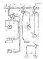
- An oil-air mixture (in which the oil is not contained in a nebulized state but in a drop-shaped state) is introduced in a turbulent air flow in the direction of arrow A in a line 1 from a central device (not shown).
- the line 1 has several distributors 2, 3, 4 ..., to which branch lines 5, 6, 7 connect. Further distributors 8, 16, 9, 10 and 11 are connected to the branch lines. From these distributors, the oil-air mixture, which is denoted by 12, is supplied with friction points or lubrication points, which can be designed as roller bearings, slide bearings, sliding surfaces, gear wheels, chains or the like, and which are shown schematically in FIG. 1 .
- the branch lines leading to the friction points are designated 13 in the distributor 8 and 14 and 15 in the distributor 16.
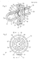
- the distributor 16 is shown schematically on an enlarged scale in FIGS. 2 and 3 and is explained below.
- the line 5 forms in its interior an inlet channel 17 for an inlet flow in the direction of arrow B for the oil drops brought up in a turbulent air flow.
- the input channel 17 has a closed one Front end 18 on.
- a total of ten intermediate channels 19 to 28 are arranged distributed in the radial direction over the inner circumference of the input channel 17.
- the intermediate channels 19, 21, 23, 25 and 27 all lead into an outlet channel 29 through which the oil-air mixture is fed to the friction point in the direction of arrow C.
- the intermediate channels 20, 22, 24, 26 and 28 lying between the just mentioned intermediate channels all open into an annular channel 30, which in turn opens into a channel 31, in which oil-air mixture flows in the direction of arrow D.
- Throttle devices 32 and 33 are provided in the output channels 29 and 31, respectively, by means of which the cross section of the output channels can be designed to be of different sizes. This enables a wide range of variations in the distribution ratios. If, for example, the throttle device has an opening radius of 0.1 mm, then this corresponds to a cross section of 0.0314 mm 2 . In contrast, if the opening of the throttle device in another output channel has a bore with a radius of 0.2 mm, this corresponds to a cross-section of 0.1256 mm 2 , i.e. four times the cross-sectional value of the other output channel (assuming that contrary to the neichnerical Representation the cross sections of the output channels are the same size). If the radius of a hole is 1 mm, the cross-section is already a hundred times the value compared to a hole of 0.1 mm radius.
- the carrier medium prefferably be the working medium at the same time.
Landscapes
- Engineering & Computer Science (AREA)
- General Engineering & Computer Science (AREA)
- Chemical & Material Sciences (AREA)
- Combustion & Propulsion (AREA)
- Oil, Petroleum & Natural Gas (AREA)
- Mechanical Engineering (AREA)
- General Details Of Gearings (AREA)
- Lubricants (AREA)
Priority Applications (1)
| Application Number | Priority Date | Filing Date | Title |
|---|---|---|---|
| AT79103935T ATE1113T1 (de) | 1978-10-16 | 1979-10-12 | Verfahren zum aufteilen eines in einem traegermedium herangefuehrten, tropfenfoermigen schmiermediums in wenigstens zwei voneinander getrennte ausgangsstroemungen sowie vorrichtung zur durchfuehrung dieses verfahrens. |
Applications Claiming Priority (2)
| Application Number | Priority Date | Filing Date | Title |
|---|---|---|---|
| DE2844995A DE2844995C3 (de) | 1978-10-16 | 1978-10-16 | Vorrichtung zum Aufteilen eines in einem Trägermedium herangeführten tropfenförmigen Schmiermediums |
| DE2844995 | 1978-10-16 |
Publications (2)
| Publication Number | Publication Date |
|---|---|
| EP0010269A1 true EP0010269A1 (fr) | 1980-04-30 |
| EP0010269B1 EP0010269B1 (fr) | 1982-05-26 |
Family
ID=6052303
Family Applications (1)
| Application Number | Title | Priority Date | Filing Date |
|---|---|---|---|
| EP79103935A Expired EP0010269B1 (fr) | 1978-10-16 | 1979-10-12 | Procédé et dispositif pour diviser un courant de lubrifiant en gouttelettes amené dans un milieu porteur en au moins deux courants de sortie séparés |
Country Status (3)
| Country | Link |
|---|---|
| EP (1) | EP0010269B1 (fr) |
| AT (1) | ATE1113T1 (fr) |
| DE (1) | DE2844995C3 (fr) |
Cited By (5)
| Publication number | Priority date | Publication date | Assignee | Title |
|---|---|---|---|---|
| US5253733A (en) * | 1991-08-20 | 1993-10-19 | Koyo Seiko Co., Ltd. | Oil and air lubrication device |
| DE29609855U1 (de) * | 1996-06-04 | 1996-08-08 | REBS Zentralschmiertechnik GmbH, 40885 Ratingen | Vorrichtung zum Aufteilen einer mittels einer Gasströmung transportierten viskosen Flüssigkeit |
| DE19632546C2 (de) * | 1996-08-13 | 2000-04-27 | Rebs Zentralschmiertech Gmbh | Turbulenzverteiler |
| WO2005022025A1 (fr) * | 2003-07-29 | 2005-03-10 | Delimon Gmbh | Dispositif pour repartir un milieu visqueux transporte dans un flux gazeux, notamment un agent lubrifiant tel que de l'huile |
| US9415430B2 (en) | 2007-09-12 | 2016-08-16 | Sms Siemag Ag | Roll stand for rolling metallic strips and roll or cylinder for a roll stand of this type |
Families Citing this family (13)
| Publication number | Priority date | Publication date | Assignee | Title |
|---|---|---|---|---|
| US4359141A (en) * | 1980-11-21 | 1982-11-16 | Horst Schnell | Lubricating system |
| DE4039169A1 (de) * | 1990-12-05 | 1992-07-02 | Vogel Willi Ag | Vorrichtung zum aufteilen eines oel-luft-stromes |
| DE4126198C1 (en) * | 1991-08-08 | 1992-07-16 | Horst Dipl.-Ing. 4052 Korschenbroich De Schnell | Dividing lubricant droplets stream in flow duct - separates lubricant and carrier medium in flow duct cross=sectional, peripheral widening |
| JP3413437B2 (ja) | 1991-08-20 | 2003-06-03 | 光洋精工株式会社 | オイルアンドエア潤滑装置 |
| DE4439380A1 (de) * | 1994-11-04 | 1996-05-09 | Bielomatik Leuze & Co | Schmiereinrichtung sowie Verfahren zur schmierenden Beaufschlagung mindestens einer Schmierstelle |
| UA47950C2 (ru) * | 2001-11-30 | 2008-10-27 | Николай Алексеевич Юрченко | Централизованная автоматизированная система смазки подшипниковых узлов валковых опор прокатной клети масловоздушной пленкой и способ осуществления смазки |
| DE102005010132B4 (de) * | 2005-03-02 | 2008-02-07 | Rebs Zentralschmiertechnik Gmbh | Vorrichtung zum Aufteilen eines mittels eines Luftstroms geförderten Schmierstoffstroms |
| DE102006059838B3 (de) * | 2006-12-15 | 2008-04-03 | Rebs Zentralschmiertechnik Gmbh | Vorrichtung und Verfahren zur Schmierstoffversorgung eines Wälzlagers und mit einer solchen Vorrichtung ausgestattetes Walzgerüst |
| DE102007019653B4 (de) | 2007-04-26 | 2010-07-01 | Rebs Zentralschmiertechnik Gmbh | Vorrichtung zum Aufteilen eines mittels eines Gasstroms geförderten Schmierstoffstroms und mit einer solchen Vorrichtung ausgestattete Maschine |
| DE202007018826U1 (de) | 2007-09-12 | 2009-05-20 | Rebs Zentralschmiertechnik Gmbh | Walzgerüst zum Walzen von metallischen Bändern sowie Walze oder Rolle für ein solches Walzgerüst |
| DE202008007718U1 (de) | 2008-06-10 | 2008-09-04 | Rebs Zentralschmiertechnik Gmbh | Walzgerüst zum Walzen von metallischen Bändern sowie Walze oder Rolle für ein solches Walzgerüst |
| DE102009058177B4 (de) | 2009-12-15 | 2021-08-05 | Rebs Zentralschmiertechnik Gmbh | Vorrichtung zum Ankoppeln einer eine Schmierstoff-Gas-Strömung führenden Versorgungsleitung an einer Maschine und mit einer solchen Vorrichtung ausgestattete Maschine |
| CN105003811A (zh) * | 2015-07-29 | 2015-10-28 | 安徽丹凤集团桐城玻璃纤维有限公司 | 拉丝机油雾器管路 |
Citations (4)
| Publication number | Priority date | Publication date | Assignee | Title |
|---|---|---|---|---|
| US2334942A (en) * | 1941-06-20 | 1943-11-23 | Hopewood Mfg Company | Lubrication system |
| CH260169A (de) * | 1943-04-01 | 1949-02-28 | Power Jets Res & Dev Ltd | Schmiereinrichtung an einer Maschine mit einer Anzahl von Schmierstellen. |
| US2959249A (en) * | 1957-10-23 | 1960-11-08 | Skf Svenska Kullagerfab Ab | Oil mist lubricating method |
| US3665684A (en) * | 1970-06-29 | 1972-05-30 | Norman O White | Oil mist reclassifying system |
Family Cites Families (2)
| Publication number | Priority date | Publication date | Assignee | Title |
|---|---|---|---|---|
| DE504970C (de) * | 1930-08-12 | Louis Renault | Selbsttaetige Zentralschmiervorrichtung fuer Kraftfahrzeuge | |
| DE455504C (de) * | 1924-11-29 | 1928-02-03 | Heinrich Emil Wencke | OElstaubschmiervorrichtung fuer Lager |
-
1978
- 1978-10-16 DE DE2844995A patent/DE2844995C3/de not_active Expired
-
1979
- 1979-10-12 EP EP79103935A patent/EP0010269B1/fr not_active Expired
- 1979-10-12 AT AT79103935T patent/ATE1113T1/de not_active IP Right Cessation
Patent Citations (4)
| Publication number | Priority date | Publication date | Assignee | Title |
|---|---|---|---|---|
| US2334942A (en) * | 1941-06-20 | 1943-11-23 | Hopewood Mfg Company | Lubrication system |
| CH260169A (de) * | 1943-04-01 | 1949-02-28 | Power Jets Res & Dev Ltd | Schmiereinrichtung an einer Maschine mit einer Anzahl von Schmierstellen. |
| US2959249A (en) * | 1957-10-23 | 1960-11-08 | Skf Svenska Kullagerfab Ab | Oil mist lubricating method |
| US3665684A (en) * | 1970-06-29 | 1972-05-30 | Norman O White | Oil mist reclassifying system |
Cited By (5)
| Publication number | Priority date | Publication date | Assignee | Title |
|---|---|---|---|---|
| US5253733A (en) * | 1991-08-20 | 1993-10-19 | Koyo Seiko Co., Ltd. | Oil and air lubrication device |
| DE29609855U1 (de) * | 1996-06-04 | 1996-08-08 | REBS Zentralschmiertechnik GmbH, 40885 Ratingen | Vorrichtung zum Aufteilen einer mittels einer Gasströmung transportierten viskosen Flüssigkeit |
| DE19632546C2 (de) * | 1996-08-13 | 2000-04-27 | Rebs Zentralschmiertech Gmbh | Turbulenzverteiler |
| WO2005022025A1 (fr) * | 2003-07-29 | 2005-03-10 | Delimon Gmbh | Dispositif pour repartir un milieu visqueux transporte dans un flux gazeux, notamment un agent lubrifiant tel que de l'huile |
| US9415430B2 (en) | 2007-09-12 | 2016-08-16 | Sms Siemag Ag | Roll stand for rolling metallic strips and roll or cylinder for a roll stand of this type |
Also Published As
| Publication number | Publication date |
|---|---|
| ATE1113T1 (de) | 1982-06-15 |
| DE2844995B2 (de) | 1980-11-27 |
| DE2844995A1 (de) | 1980-04-17 |
| DE2844995C3 (de) | 1981-09-10 |
| EP0010269B1 (fr) | 1982-05-26 |
Similar Documents
| Publication | Publication Date | Title |
|---|---|---|
| EP0010269B1 (fr) | Procédé et dispositif pour diviser un courant de lubrifiant en gouttelettes amené dans un milieu porteur en au moins deux courants de sortie séparés | |
| EP0902868B1 (fr) | Procede pour diviser un fluide visqueux transporte par un flux gazeux | |
| DE2234488A1 (de) | Einrichtung zum schmieren der zahnflanken von zahnraedern | |
| DE2618948C3 (de) | Düse für eine Vorrichtung zur kontinuierlichen ölschmierung von - freilaufenden - Maschinenelementen | |
| DE2801083C2 (de) | Automatisches Steuerventil zum Durchlassen eines für Verbraucher bestimmten, unter Eingangsdruck stehenden Fluidums in festgesetzten Mengen | |
| WO2008132107A2 (fr) | Dispositif de répartition d'un flux de lubrifiant transporté au moyen d'un flux de gaz | |
| DE2105077A1 (de) | Vorrichtung zum gleichmäßigen Verteilen von Luft innerhalb von an Luftverteilkanäle einer Klimaanlage angeschlossenen Räumen | |
| AT507433B1 (de) | Druckluftöler | |
| DE4126198C1 (en) | Dividing lubricant droplets stream in flow duct - separates lubricant and carrier medium in flow duct cross=sectional, peripheral widening | |
| DE3936080C2 (de) | Verfahren zum Variieren der Umfangsgeschwindigkeitskomponente der Drallströmung eines Fluids | |
| DE4039169C2 (fr) | ||
| EP1649206B1 (fr) | Dispositif pour repartir un milieu visqueux transporte dans un flux gazeux, notamment un agent lubrifiant tel que de l'huile | |
| EP1419339B1 (fr) | Procede et dispositif permettant de lubrifier des points de lubrification avec des quantites minimales de lubrifiant | |
| DE202021104106U1 (de) | Vorrichtung zum Aufteilen einer mittels einer Gasströmung transportierten Flüssigkeit | |
| DE2145131B2 (de) | Vorrichtung zum gleichmäßigen und stufenlos veränderbaren Einölen von kontinuierlich bewegtem Walzgut, insbesondere von Blechbändern oder -tafeln | |
| EP1853845B1 (fr) | Dispositif destine a distribuer un flux de lubrifiant refoule au moyen d'un flux d'air | |
| DE29609855U1 (de) | Vorrichtung zum Aufteilen einer mittels einer Gasströmung transportierten viskosen Flüssigkeit | |
| EP0643253A1 (fr) | Système de graissage par pulvérisation pour un graissage à air au moyen d'huile ou de graisse | |
| EP1748851A1 (fr) | Dispositif et procede pour repartir un liquide visqueux transporte par ecoulement gazeux, en au moins deux courants partiels | |
| EP0603631A1 (fr) | Dispositif de moulage par injection | |
| DE947275C (de) | Druckluftverteiler fuer die Zerstaeubung des von einer kraftangetriebenen Schmiervorrichtung zu Schmierduesen gefoerderten Schmiermittels | |
| DE467768C (de) | Schmiervorrichtung, insbesondere fuer Kraftwagen | |
| DE102022121637A1 (de) | Luftlose Schmiermittelanlage | |
| DE351951C (fr) | ||
| DE102005054907A1 (de) | Schmiersystem sowie Verfahren zum Schmieren |
Legal Events
| Date | Code | Title | Description |
|---|---|---|---|
| PUAI | Public reference made under article 153(3) epc to a published international application that has entered the european phase |
Free format text: ORIGINAL CODE: 0009012 |
|
| AK | Designated contracting states |
Designated state(s): AT BE CH FR GB IT LU NL SE |
|
| 17P | Request for examination filed | ||
| ITF | It: translation for a ep patent filed | ||
| GRAA | (expected) grant |
Free format text: ORIGINAL CODE: 0009210 |
|
| AK | Designated contracting states |
Designated state(s): AT BE CH FR GB IT LU NL SE |
|
| PG25 | Lapsed in a contracting state [announced via postgrant information from national office to epo] |
Ref country code: SE Effective date: 19820526 Ref country code: NL Effective date: 19820526 Ref country code: BE Effective date: 19820526 |
|
| REF | Corresponds to: |
Ref document number: 1113 Country of ref document: AT Date of ref document: 19820615 Kind code of ref document: T |
|
| PGFP | Annual fee paid to national office [announced via postgrant information from national office to epo] |
Ref country code: AT Payment date: 19821015 Year of fee payment: 4 |
|
| NLV1 | Nl: lapsed or annulled due to failure to fulfill the requirements of art. 29p and 29m of the patents act | ||
| PGFP | Annual fee paid to national office [announced via postgrant information from national office to epo] |
Ref country code: LU Payment date: 19821021 Year of fee payment: 4 |
|
| PG25 | Lapsed in a contracting state [announced via postgrant information from national office to epo] |
Ref country code: LU Free format text: LAPSE BECAUSE OF NON-PAYMENT OF DUE FEES Effective date: 19821031 |
|
| PG25 | Lapsed in a contracting state [announced via postgrant information from national office to epo] |
Ref country code: AT Effective date: 19831012 |
|
| PGFP | Annual fee paid to national office [announced via postgrant information from national office to epo] |
Ref country code: CH Payment date: 19831229 Year of fee payment: 5 |
|
| PG25 | Lapsed in a contracting state [announced via postgrant information from national office to epo] |
Ref country code: CH Effective date: 19841031 |
|
| GBPC | Gb: european patent ceased through non-payment of renewal fee | ||
| REG | Reference to a national code |
Ref country code: CH Ref legal event code: PL |
|
| PG25 | Lapsed in a contracting state [announced via postgrant information from national office to epo] |
Ref country code: GB Effective date: 19881118 |
|
| ITTA | It: last paid annual fee | ||
| PGFP | Annual fee paid to national office [announced via postgrant information from national office to epo] |
Ref country code: FR Payment date: 19980928 Year of fee payment: 20 |
|
| PLBE | No opposition filed within time limit |
Free format text: ORIGINAL CODE: 0009261 |
|
| STAA | Information on the status of an ep patent application or granted ep patent |
Free format text: STATUS: NO OPPOSITION FILED WITHIN TIME LIMIT |