EP0010277A1 - Montant latéral pour meuble de bureau - Google Patents
Montant latéral pour meuble de bureau Download PDFInfo
- Publication number
- EP0010277A1 EP0010277A1 EP19790103951 EP79103951A EP0010277A1 EP 0010277 A1 EP0010277 A1 EP 0010277A1 EP 19790103951 EP19790103951 EP 19790103951 EP 79103951 A EP79103951 A EP 79103951A EP 0010277 A1 EP0010277 A1 EP 0010277A1
- Authority
- EP
- European Patent Office
- Prior art keywords
- side frame
- frame according
- profile
- cable duct
- cable
- Prior art date
- Legal status (The legal status is an assumption and is not a legal conclusion. Google has not performed a legal analysis and makes no representation as to the accuracy of the status listed.)
- Ceased
Links
- 101100453790 Drosophila melanogaster Kebab gene Proteins 0.000 description 1
- 230000004308 accommodation Effects 0.000 description 1
- 230000005540 biological transmission Effects 0.000 description 1
- 230000000295 complement effect Effects 0.000 description 1
- 238000010276 construction Methods 0.000 description 1
- 238000000605 extraction Methods 0.000 description 1
- 238000007373 indentation Methods 0.000 description 1
- 235000015231 kebab Nutrition 0.000 description 1
- 239000002184 metal Substances 0.000 description 1
- 238000007789 sealing Methods 0.000 description 1
Images


Classifications
-
- A—HUMAN NECESSITIES
- A47—FURNITURE; DOMESTIC ARTICLES OR APPLIANCES; COFFEE MILLS; SPICE MILLS; SUCTION CLEANERS IN GENERAL
- A47B—TABLES; DESKS; OFFICE FURNITURE; CABINETS; DRAWERS; GENERAL DETAILS OF FURNITURE
- A47B21/00—Tables or desks for office equipment, e.g. typewriters, keyboards
- A47B21/06—Tables or desks for office equipment, e.g. typewriters, keyboards characterised by means for holding, fastening or concealing cables
-
- A—HUMAN NECESSITIES
- A47—FURNITURE; DOMESTIC ARTICLES OR APPLIANCES; COFFEE MILLS; SPICE MILLS; SUCTION CLEANERS IN GENERAL
- A47B—TABLES; DESKS; OFFICE FURNITURE; CABINETS; DRAWERS; GENERAL DETAILS OF FURNITURE
- A47B17/00—Writing-tables
-
- H—ELECTRICITY
- H02—GENERATION; CONVERSION OR DISTRIBUTION OF ELECTRIC POWER
- H02G—INSTALLATION OF ELECTRIC CABLES OR LINES, OR OF COMBINED OPTICAL AND ELECTRIC CABLES OR LINES
- H02G3/00—Installations of electric cables or lines or protective tubing therefor in or on buildings, equivalent structures or vehicles
- H02G3/02—Details
- H02G3/04—Protective tubing or conduits, e.g. cable ladders or cable troughs
- H02G3/0437—Channels
Definitions
- the invention relates to a side frame according to the preamble of claim 1.
- connection cables Because of the diverse use of electrical devices, such as typewriters, calculating machines, message transmission units, connection units for data processing systems and the like, in offices, a large number of connection cables often have to be laid there.
- the connecting cables are usually led from wall or floor sockets to the respective workplaces. So that the large number of cables are not lying around or hanging freely, it is common to place the cables in vertical cable channels, e.g. in the side frame of the desks to the level of the immediate work area.
- the cable duct should be closed off or concealed, particularly for aesthetic reasons. However, since the cable routing needs to be changed more often or new cables routed, the cable duct should be easily accessible for this handling.
- the laying of three cables of different cross-sections next to each other is required. However, these must be arranged in the cable duct and be easy to lay.
- the invention is intended to meet the needs outlined above with little design effort.
- the side frame can be used on the right and left, i.e. be equally accessible from both sides for cable laying.
- the inventive concept laid down in the main claim can be implemented in a simple manner in terms of construction with the measure of claim 2, the stability of the elements delimiting the cable duct, such as struts or the like, being increased.
- the Z profile and subdivision profile form a fixed unit.
- a structurally simple solution for easy removal and attachment of the cap is provided according to claim 8.
- the exposed outside of side frames should also be completely closed or covered in the area of the vertical cable duct, while in the case of adjacent side frames of adjacent desks and horizontally continuous cable routing, a lateral outlet for the cables at the upper end of the vertical cable duct must be kept free. In order to be able to easily implement these alternatives, the measure of claim 10 has been taken.
- the already existing cams of the upper end cap are used at the same time for releasably fixing the upper cover element.
- the side frame - 1 of a desk is designed as an n-frame, in whose vertical strut 22 a vertical cable duct 2 is formed.
- the cable duct 2 is delimited by two square tubes 23, which are arranged at a distance from one another at the lower end, between the side wall surfaces 6 facing one another.
- the vertical cable duct 2 is diagonally divided into two approximately wedge-shaped vertical cable duct sections 3 and 4 by a Z-profile 5 extending essentially over the entire height of the cable duct 2, which complement each other to form the overall cross section of the cable duct 2.
- the Z-profile 5 is attached to the free legs on the side wall surfaces 6, for example welded to them when both the square tubes 23 a's and the Z-profile 5 are made of metal.
- a dividing profile 8, for example made of plastic, with outward-pointing ribs 7 divides the channel sections 3 and 4 into vertically adjacent cable chambers 9, 10 and 11.
- the cable with the largest cross-section can , in the cable chamber 10 with the medium cross section and in the cable chamber 11 with the smallest cross section side by side.
- the ribs 7 are provided on their outer longitudinal edges with locking grooves, in which inward-pointing resilient clamping lugs 13 of side cover plates 12, which are also made of plastic, for example, are attached.
- the respective cover plate 12 rests with its outer vertical longitudinal edges on the one hand on one leg of the Z profile 5 and on the other hand on the outer edge of an outer rib 24 of the subdivision profile 8; so that the outer surface of the cover plate 12 is flush with the adjacent square tubes 23, the leg and the rib 24 are set back according to the thickness of the cover plate 12.
- a swiveling flap 14 according to FIGS. 6a and 6b is provided at the lower end of at least one cover plate 12, which has a correspondingly smaller vertical length, for the exit or entry of the cables into the vertical cable duct 2.
- the flap 14 consists essentially of a plate part 25, from which project at its lower edge inwardly tapered side legs 26. On the side legs 26, laterally outward elevations or cams 27 are formed, by means of which the flap 14 can be pivoted in corresponding recesses or
- the flap 14 can therefore be made in one piece from plastic.
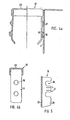
- the cover plates 12 do not extend to the upper edge of the cable duct 2 open at the top. Rather, an end cap 15 can be inserted into the cable duct 2 from above, which is connected in more detail in FIGS. 4a and 4b.
- the cap 15 has a head section 28, from which elastically resilient tabs 18 project downward.
- the tabs 18 are adjacent to the side wall surfaces 6 which delimit the cable duct 2.
- the tabs 18 with cams 16 snap into corresponding holes or recesses 17 in the side wall surfaces 6.
- two tabs 16 are arranged one above the other on each tab, of which the upper tapers conically and the lower tapered only at the lower edge is.
- end cap 15 can be easily inserted into the cable duct from above under low pressure.
- extraction is only possible if the two tabs 18 are pressed inwards by hand at the lower edge. To facilitate the engagement, the tabs 18 are therefore bent inwards at the lower end towards the central plane of the cap 15.
- the end cap 15 can also be made in one piece from plastic.
- the part of the vertical cable duct 2 which is still exposed after the end cap 15 has been placed over the cover plates, where no cables have to be led out, can be closed off by a separate cover element 19.
- the cover element 19 consists of a base plate 29, from which side cheeks 20 point into the interior of the channel. In the cheeks 20 there are at least one of clamping lips 21 laterally limited indentations 30 are kept free, with the aid of which the respective cover element 19 can be plugged onto the cams 16 of the end cap 15. These cover elements 19 can therefore each be dismantled and attached without the need for special tools.
Landscapes
- Engineering & Computer Science (AREA)
- Architecture (AREA)
- Civil Engineering (AREA)
- Structural Engineering (AREA)
- Details Of Indoor Wiring (AREA)
- Installation Of Indoor Wiring (AREA)
Applications Claiming Priority (2)
| Application Number | Priority Date | Filing Date | Title |
|---|---|---|---|
| DE7831543U | 1978-10-23 | ||
| DE19787831543 DE7831543U1 (de) | 1978-10-23 | 1978-10-23 | Seitengestell fuer bueromoebel |
Publications (1)
| Publication Number | Publication Date |
|---|---|
| EP0010277A1 true EP0010277A1 (fr) | 1980-04-30 |
Family
ID=6696299
Family Applications (1)
| Application Number | Title | Priority Date | Filing Date |
|---|---|---|---|
| EP19790103951 Ceased EP0010277A1 (fr) | 1978-10-23 | 1979-10-15 | Montant latéral pour meuble de bureau |
Country Status (2)
| Country | Link |
|---|---|
| EP (1) | EP0010277A1 (fr) |
| DE (2) | DE7831543U1 (fr) |
Cited By (15)
| Publication number | Priority date | Publication date | Assignee | Title |
|---|---|---|---|---|
| GB2139488A (en) * | 1983-05-11 | 1984-11-14 | Mines & West Ltd | Improvements in and relating to desking systems |
| US4612863A (en) * | 1982-10-23 | 1986-09-23 | Voko Franz Vogt & Co. | Work table |
| GB2180149A (en) * | 1985-09-05 | 1987-03-25 | Arenson Int Ltd | Desk |
| US4688748A (en) * | 1985-08-13 | 1987-08-25 | Ahrend Groep B.V. | Support construction for desk- or table-top |
| US4734826A (en) * | 1986-03-10 | 1988-03-29 | Haworth, Inc. | Work surface with channel for power communication cabling |
| EP0236809A3 (fr) * | 1986-03-10 | 1988-07-20 | VS Vereinigte Spezialmöbelfabriken Verwaltungs-GmbH | Bureau support d'appareils, en particulier d'informatique |
| EP0398014A1 (fr) * | 1989-05-17 | 1990-11-22 | OTTO LAMPERTZ, FABRIKEN FÜR ORGANISATIONSMITTEL UND EDV-ZUBEHÖR GMBH & CO. KG | Système d'ameublement variable pour atelier |
| WO1991016835A1 (fr) * | 1990-05-02 | 1991-11-14 | 3K Büromöbel Gmbh | Elements lateraux pour meubles de bureau |
| EP0462920A1 (fr) * | 1990-06-18 | 1991-12-27 | Mobel Linea, S.L. | Structure pour la formation de meubles de bureau et similaires |
| GB2247613A (en) * | 1990-09-07 | 1992-03-11 | Martina Limited | A frame for a desk |
| GB2337453A (en) * | 1998-05-01 | 1999-11-24 | Ditto Sales Inc | Cable management apparatus for furniture leg. |
| WO1999065126A1 (fr) * | 1998-06-12 | 1999-12-16 | Giuseppe Formuso | Elements, enveloppes, coques, panneaux et canaux permettant de recouvrir des cables, en particulier pour des appareils electriques et/ou electroniques situes sur un plan de travail |
| US6216606B1 (en) * | 1998-03-10 | 2001-04-17 | Jayashree R. Kathardekar | Article of furniture |
| US6254206B1 (en) * | 1999-02-16 | 2001-07-03 | Bretford Manufacturing, Inc. | Wire manager |
| US6732661B2 (en) * | 2001-10-11 | 2004-05-11 | Sedus Stoll Ag | Moving table flap |
Families Citing this family (6)
| Publication number | Priority date | Publication date | Assignee | Title |
|---|---|---|---|---|
| US4762072A (en) * | 1986-10-07 | 1988-08-09 | Westinghouse Electric Corp. | Desk and space dividing wall panel assembly |
| US4843707A (en) * | 1987-08-19 | 1989-07-04 | Sanders Associates, Inc. | Cable retention system |
| US5709156A (en) * | 1995-06-07 | 1998-01-20 | Krueger International, Inc. | Flip-up electrical and communications device for use in combination with a worksurface |
| US5673632A (en) * | 1996-01-03 | 1997-10-07 | Sykes; Christopher C. | Workstation having L-shaped worktop and flat-folding legs |
| US6327983B1 (en) * | 1999-03-03 | 2001-12-11 | Steelcase Development Corporation | Conference table with central utility system |
| US6979209B2 (en) | 2003-01-29 | 2005-12-27 | Krueger International, Inc. | Biased utility receptacle assembly |
Citations (2)
| Publication number | Priority date | Publication date | Assignee | Title |
|---|---|---|---|---|
| US1786823A (en) * | 1927-03-17 | 1930-12-30 | Westinghouse Electric & Mfg Co | Desk |
| FR1561565A (fr) * | 1968-03-27 | 1969-03-28 |
-
1978
- 1978-10-23 DE DE19787831543 patent/DE7831543U1/de not_active Expired
-
1979
- 1979-04-20 DE DE19792916002 patent/DE2916002A1/de not_active Ceased
- 1979-10-15 EP EP19790103951 patent/EP0010277A1/fr not_active Ceased
Patent Citations (2)
| Publication number | Priority date | Publication date | Assignee | Title |
|---|---|---|---|---|
| US1786823A (en) * | 1927-03-17 | 1930-12-30 | Westinghouse Electric & Mfg Co | Desk |
| FR1561565A (fr) * | 1968-03-27 | 1969-03-28 |
Cited By (17)
| Publication number | Priority date | Publication date | Assignee | Title |
|---|---|---|---|---|
| US4612863A (en) * | 1982-10-23 | 1986-09-23 | Voko Franz Vogt & Co. | Work table |
| GB2139488A (en) * | 1983-05-11 | 1984-11-14 | Mines & West Ltd | Improvements in and relating to desking systems |
| US4688748A (en) * | 1985-08-13 | 1987-08-25 | Ahrend Groep B.V. | Support construction for desk- or table-top |
| GB2180149A (en) * | 1985-09-05 | 1987-03-25 | Arenson Int Ltd | Desk |
| GB2180149B (en) * | 1985-09-05 | 1990-01-24 | Arenson Int Ltd | Improvements in desks |
| US4734826A (en) * | 1986-03-10 | 1988-03-29 | Haworth, Inc. | Work surface with channel for power communication cabling |
| EP0236809A3 (fr) * | 1986-03-10 | 1988-07-20 | VS Vereinigte Spezialmöbelfabriken Verwaltungs-GmbH | Bureau support d'appareils, en particulier d'informatique |
| EP0398014A1 (fr) * | 1989-05-17 | 1990-11-22 | OTTO LAMPERTZ, FABRIKEN FÜR ORGANISATIONSMITTEL UND EDV-ZUBEHÖR GMBH & CO. KG | Système d'ameublement variable pour atelier |
| WO1991016835A1 (fr) * | 1990-05-02 | 1991-11-14 | 3K Büromöbel Gmbh | Elements lateraux pour meubles de bureau |
| EP0462920A1 (fr) * | 1990-06-18 | 1991-12-27 | Mobel Linea, S.L. | Structure pour la formation de meubles de bureau et similaires |
| GB2247613A (en) * | 1990-09-07 | 1992-03-11 | Martina Limited | A frame for a desk |
| US6216606B1 (en) * | 1998-03-10 | 2001-04-17 | Jayashree R. Kathardekar | Article of furniture |
| GB2337453A (en) * | 1998-05-01 | 1999-11-24 | Ditto Sales Inc | Cable management apparatus for furniture leg. |
| GB2337453B (en) * | 1998-05-01 | 2002-01-16 | Ditto Sales Inc | Wire management apparatus |
| WO1999065126A1 (fr) * | 1998-06-12 | 1999-12-16 | Giuseppe Formuso | Elements, enveloppes, coques, panneaux et canaux permettant de recouvrir des cables, en particulier pour des appareils electriques et/ou electroniques situes sur un plan de travail |
| US6254206B1 (en) * | 1999-02-16 | 2001-07-03 | Bretford Manufacturing, Inc. | Wire manager |
| US6732661B2 (en) * | 2001-10-11 | 2004-05-11 | Sedus Stoll Ag | Moving table flap |
Also Published As
| Publication number | Publication date |
|---|---|
| DE7831543U1 (de) | 1979-02-15 |
| DE2916002A1 (de) | 1980-11-13 |
Similar Documents
| Publication | Publication Date | Title |
|---|---|---|
| EP0010277A1 (fr) | Montant latéral pour meuble de bureau | |
| DE2424484C2 (de) | Möbelsystem | |
| DE2927114A1 (de) | Regalsystem | |
| DE29713298U1 (de) | Trennwandeinheit | |
| EP0706012A1 (fr) | Four de boulanger | |
| DE2256853A1 (de) | Schubschrank mit gleitbahnen fuer verschiebbare schubfaecher oder schubkaesten | |
| DE102006058779A1 (de) | Schaltschrankanordnung | |
| DE2625202C3 (de) | Haushaltgerät z.B. Geschirrspülmaschine mit einem frontseitigen Sockelrücksprung | |
| DE3686993T2 (de) | Basis mit kanaelen fuer trennungspaneele. | |
| DE19610347C1 (de) | Kabelkanalsystem für Büroeinrichtungen, insbesondere für EDV-Arbeitsplätze o. dgl. | |
| WO1996024236A1 (fr) | Armoire de distribution avec baie et plaque de montage | |
| EP1123572A1 (fr) | Jeu de pieces pour constituer des conduits de cables d'un meuble de bureau | |
| EP0236809A2 (fr) | Bureau support d'appareils, en particulier d'informatique | |
| DE10007431A1 (de) | Vorrichtung zum Aufteilen von Büroräumen | |
| DE10103934C2 (de) | Schranksystem | |
| DE3142858A1 (de) | "schrankwand oder regal mit einem sockel und mit faechern zur aufnahme von elektrischen geraeten, insbesondere von medienvermittlungsgeraeten o.dgl." | |
| EP1145666B1 (fr) | Etagère en particulier pour des bibliothèques | |
| DE9112637U1 (de) | Arbeitstisch | |
| DE2350354A1 (de) | Blende fuer eine schublade | |
| DE8701711U1 (de) | Haltevorrichtung für Montagerückwände | |
| DE10112000C1 (de) | Geräteschrank | |
| DE2216129A1 (de) | Arbeitstisch mit im tisch verlegten elektrischen zuleitungen | |
| DE29904707U1 (de) | Rahmengestell für einen Schrank | |
| DE2328235C3 (de) | Mehrzweckinstallationskanal zur Wandverlegung, insbesondere für die Gebäudeelektroinstallation | |
| DE102014017627A1 (de) | Regal - und / oder Raumteilervorrichtung |
Legal Events
| Date | Code | Title | Description |
|---|---|---|---|
| PUAI | Public reference made under article 153(3) epc to a published international application that has entered the european phase |
Free format text: ORIGINAL CODE: 0009012 |
|
| AK | Designated contracting states |
Designated state(s): AT BE CH FR GB IT LU NL SE |
|
| 17P | Request for examination filed | ||
| STAA | Information on the status of an ep patent application or granted ep patent |
Free format text: STATUS: THE APPLICATION HAS BEEN REFUSED |
|
| 18R | Application refused |
Effective date: 19840518 |
|
| RIN1 | Information on inventor provided before grant (corrected) |
Inventor name: BITTERBERG, KARL-GEORG, PROF. Inventor name: KRAETSCHMER, SIEGFRIED |