EP0010329B1 - Convertisseur de couple - Google Patents
Convertisseur de couple Download PDFInfo
- Publication number
- EP0010329B1 EP0010329B1 EP79200581A EP79200581A EP0010329B1 EP 0010329 B1 EP0010329 B1 EP 0010329B1 EP 79200581 A EP79200581 A EP 79200581A EP 79200581 A EP79200581 A EP 79200581A EP 0010329 B1 EP0010329 B1 EP 0010329B1
- Authority
- EP
- European Patent Office
- Prior art keywords
- friction
- torque converter
- axis
- friction element
- anyone
- Prior art date
- Legal status (The legal status is an assumption and is not a legal conclusion. Google has not performed a legal analysis and makes no representation as to the accuracy of the status listed.)
- Expired
Links
Images


Classifications
-
- F—MECHANICAL ENGINEERING; LIGHTING; HEATING; WEAPONS; BLASTING
- F16—ENGINEERING ELEMENTS AND UNITS; GENERAL MEASURES FOR PRODUCING AND MAINTAINING EFFECTIVE FUNCTIONING OF MACHINES OR INSTALLATIONS; THERMAL INSULATION IN GENERAL
- F16H—GEARING
- F16H15/00—Gearings for conveying rotary motion with variable gear ratio, or for reversing rotary motion, by friction between rotary members
- F16H15/48—Gearings for conveying rotary motion with variable gear ratio, or for reversing rotary motion, by friction between rotary members with members having orbital motion
- F16H15/50—Gearings providing a continuous range of gear ratios
Definitions
- This invention relates to a torque converter comprising at least two friction elements which are mounted for rotation about respective rotary axes which are inclined to a main axis of the torque converter, each of the friction elements, in operation, frictionally engaging friction surfaces of the other one as well as a friction surface of a control member while rolling on one another.
- a torque converter of the type specified (FR-E 72,565) comprises resilient mechanical means which has to afford a mutual pressure between the friction elements as well as between the friction elements and the friction surfaces of the control member, in order to constitute torque transmission through the converter.
- the mechanical means are able to maintain a relatively small mutual pressure and, therefore, the maximum torque transmission is restricted.
- considerable wear and abrasion between the friction elements and the friction surface can be expected.
- An object of the invention is to provide a torque converter of the type specified which is, at a given size, to transmit relatively large torque values.
- the frictional engagement between / the friction elements with each other and between the friction elements and the control members is effected solely under the action of centrifugal force.
- the maximum torque to be transmitted can be raised to relative high values by selection of appropriate masses of the friction elements.
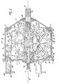
- the torque converter of Figures 1 to 5 comprises an input shaft 1 and an output shaft 2, both of which are journalled in a housing 3.
- This housing 3 comprises a cylindrical portion 6 to which end portions 4 and 5 are rigidly connected by bolts 7.
- the centrelines of the input shaft 1 and of the output shaft 2 lie on a common centreline 8; which will be referred to in this description at the "main axis" of the torque converter.
- the input shaft 1 is supported by-two axially spaced bearings 9 and 10 in a sleeve 11 which is part of the end portion 4 and is coaxial with the input shaft 1 ( Figure 1).
- the part of the input shaft 1 which projects from the housing 3 has axial splines 12, for receiving a coupling wheel or gear wheel to which the input torque is applied.
- the shaft 1 At the end of the sleeve 11 facing the shaft 2, the shaft 1 has further axial splines 13 ( Figure 3) over part of its length.
- the end of the shaft 1 facing the driven shaft 2 is supported by the shaft 2, and for this purpose the shaft 1 has a spigot carrying a bearing 14, the outer race of which is received in a cavity 15 in the end of the shaft 2 facing the shaft 1.
- the shaft 2 Near the end of the shaft 2 facing the shaft 1, the shaft 2 has axial splines 16, and the part of the shaft 2 between the splines 16 and the end portion 5 has axial splines 17, the outer diameter of which slightly exceeds that of the splines 16.
- the splines 17 extend as far as a bearing 18 ( Figure 1 which supports the driven shaft 2 in the end portion 5 of the housing 3.
- the bearings 9 and 18 need to be capable of absorbing comparatively heavy axial forces, and may therefore, for example, be tapered roller bearings.
- the part of the driven shaft 2 projecting from the housing 3 has axial splines 19, so that the shaft 2 can be provided with means for delivering the output torque to further implements or parts of a vehicle.
- the part of the input shaft 1 provided with the splines 13 has fastened to it a holder 20 having a central bore with internal splines co-operating with the splines 13 of the shaft 1.
- the holder 20 is axially retained on the driving shaft 1 by a locking ring 21 A and by the sleeve 11.
- the holder 20 has three identical arms distributed regularly about the main axis 8. This can be appreciated from Figure 2, which shows a further holder to be described later, which is substantially identical to the holder 20.
- Each of the arms of the holder 20 is provided with a sleeve 21 ( Figures 1 and 3), the centreline of which is spaced from and parallel to the main axis 8.
- Each of the three arms of the holder 20 also has a bore 22 ( Figure 3) located at a distance both from the associated sleeve 21 and from the main axis 8.
- the centreline 23 of the bore 22 ( Figure 3) is inclined to the main axis 8 and intersects it:
- the centrelines 23 of the three bores 22 of the holder 20 are located on a common control surface, the vertex of which is located on the main axis 8 and the axis of which coincides with the main axis 8.
- Each of the bores 22 of the holder 20 receives a pin 24, which is coaxial with the centreline 23.
- the material of the holder 20 around each bore 22 is removed over part of the length of the bore so that an arm 25 journalled on the pin 24 can pivot with respect to the holder 20. Therefore, the holder 20 has three arms 25, which are pivotable with respect to the holder about the associated pivotal axes 23.
- each arm 25 away from its pin 24 the arm 25 carries a rotary shaft 26 (Figure 1), which is also inclined to the main axis 8.
- the centreline 27 of the rotary shaft 26 intersects the pivotal axis 23 and the main axis 8 at the. same point, regardless of the position of the arm 25 with respect to the holder 20.
- the centreline 27 of the rotary shaft 26 is invariably located on a conical surface, the vertex of which coincides with that of the conical surface containing the centrelines 23, and the centreline of which coincides with the centreline 23 of the bore 22.
- Each of the three friction elements 28 on the holder 20 has two friction surfaces 29 and 30 (Figure 1), which meet at a common circle 31.
- the friction surface 29 of the friction element 28 is nearer the arms 25 and forms part of a conical surface, the axles of which coincides with the centreline 27 and the vertex of which is located at the point of intersection of the main axis 8, the centreline 27 of the rotary shaft 26, and the pivotal axis 23.
- the friction surface 30 of the friction element 28 is nearer the housing portion 6 and, as viewed in a cross-section through the centreline 27, is curved and thus appears approximately spherical when viewed from the adjacent part of the housing portion 6.
- the friction surface 30 is rotationally symmetrical about the centreline 27 of the rotary shaft 26, and is constituted by a surface with a curved generatrix.
- a bevel pinion 32 is rigidly connected to the rotary shaft 27 and to the friction element 28 (Figure 1).
- a further bevel pinion is mounted rotatably on the associated pin 24 by bearings 33, and the pinions 32 and 34 mesh with one another.
- the three pinions 34 associated with the three friction elements 28 all mesh with a common central pinion or sun wheel, which is coaxial with the main axis 8.
- the pinion 35 is rigidly connected with the output shaft 2 by the splines 16 ( Figure 3).
- the part of the driven shaft 2 provided with the splines 17 is surrounded by a generally cylindrical sleeve 36 having internal splines co-operating with the splines 17. Therefore, the sleeve 36 can move only axially with respect to the shaft 2, the sleeve 36 is surrounded by axially spaced bearings 37 and 38, the inner races of which engage the outer surface of the sleeve 36.
- the bearing 37 is a ball bearing, but the bearing 38 is a tapered roller bearing to withstand the axial forces generated in operation.
- the bearings 37 and 38 are fixed axially on the sleeve 36 on the one hand by a shoulder of the sleeve 36 and on the other hand by a retaining ring 39.
- the outer races of the bearings 37 and 38 support a holder 40, which is in principle identical to the holder 20 and also has three arms regularly spaced about the main axis 8 ( Figure 2).
- each arm of the holder 40 has a sleeve 41, the centreline of which is spaced from and parallel to the main axis 8.
- Each arm of the holder 40 has a bore 42 (like the bore 22 of the holder 20) the centreline 43 of which ( Figure 3) is inclined to the main axis 8 and intersects it.
- the three centrelines 43 of the three bores 42 of the holder 40 are located on a conical surface, the vertex of which is located on the main axis 8 and the axis of which coincides with the main axis 8.
- the bore 42 receives a pin 44, which is coaxial with the centreline 43 of the bore 42. Part of the material surrounding the bore 42 is removed so that an arm 45 journalled around the pivotal shaft or pin 44 can pivot with respect to the holder 40.
- a rotary shaft 46 is freely rotatable in the arm 45. The centreline 47 of the rotary shaft 46 intersects the main axis 8 at the point where the centreline 43 of the pivotal shaft 44 intersects the main axis 8.
- the centreline 47 of the rotary shaft 46 is located, in all positions of the arm 45, on a conical surface, the axis of which coincides with the centreline 43 of the bore 42, and the vertex of which coincides with the point of intersection of the centreline 43 and the main axis 8 in the same way as the corresponding parts of the holder 20 (i.e. the arms 25, the pivotal shaft 24, the rotary shaft 26).
- the rotary shaft 46 is supported by two axially spaced bearings 48 in a bore 49 of the arm 45.
- the end of the rotary shaft 46 away from the shaft 2 is provided with a friction element 50, which is freely rotatable with respect to the arm 45.
- each friction element 50 has two friction surfaces 51 and 52 meeting at a common circle 53.
- the friction surfaces 51 and 52 are of the same form as the friction surfaces 29 and 30 of the friction element 28.
- the holder 40 has three pins 44 regularly spaced apart around the main axis 8 and three friction elements 50 pivotable about the pins 44.
- Part of the length of the rotary shaft 46 has axial splines 54 and is surrounded by a sleeve 55 having a splined internal bore co-operating with the spline 54.
- Part of the sleeve 55 is constructed in the form of a bevel pinion 56, meshing with a bevel pinion 57 which is mounted on bearings 58 for free rotation about the pivotal shaft 44.
- the bearings 58 are preferably formed by tapered roller bearings. All three bevel pinions 57 of the holder 40 mesh with a central pinion or. sun wheel 59, which is coaxial with the main axis 8 and which is rigidly secured by means of splines on the sleeve 56 ( Figure 3).
- the holder 40, the three associated arms 45, the three friction elements 50, the pinions 56, 57 and 59 are axially secured to the sleeve 36 and are axially displaceable in common along the shaft 2 by sliding the sleeve 36.
- the arms of the holder 40, the disposition of the pivotal shafts 44, the shape of the arms 45, the structural form and bearing of the rotary shaft 46, the pinions 56, 57, 59 and the three friction elements 50 are identical in shape, disposition and size to the corresponding elements of the holder 20. Therefore the groups of parts are substantially symmetrical about a plane perpendicular to the main axis 8 and the holders 20 and 40.
- the conical surface, part of which is formed by the friction surface 51 of the friction element 50 is designated in Figures 1, 3 and 4 to 6 by reference 60.
- the vertex of the conical surface 60 is located on the main axis 8 and in all positions of the friction element 50 the centreline 47 of the rotary shaft 46 of the friction element 50 as well as the centreline 43 of the pivotal shaft of the arm 45 pass through the vertex of the conical surface 60.
- the conical surface of which part is formed by the conical surface 29 of the friction element 28 is designated in Figures 1, 4, 5 and 6 by reference 61.
- Alt diameters of the bores of the sleeves 21 and 41 on the arms of the holders 20 and 40 respectively are equal to one another.
- the centrelines of the sleeves 21 and 41 are aligned in pairs.
- each pair of sleeves 21 and 41 passes a connecting element in the form of a tube or rod 62, the centreline of which is parallel to the main axis 8.
- Each of the three tubes or rods 62 is fixed by a pin 63 ( Figure 3) to the associated sleeve 21.
- the sleeves 41 of the holder 40 are axially slidable along the tube or rod 62. Therefore, the holder 40 and the sleeve 36 and all parts fastened thereto are axially displaceable with respect to the holder 20 and the parts secured thereto.
- the proportions of the sleeves 21 and 41 and of the tubes or rods 62 are such that these parts can transfer a driving torque from the holder 20 to the holder 40 without impeding relative axial movement.
- the housing 3 has two internal control rings 64 and 65 ( Figures 1, 2, 4, 5 and 6). These control rings 64 and 65 are coaxial with the main axis 8 and are parallel to a plane normal to the main axis 8. The control rings 64 and 65 are disposed so that the frictional elements 28 and 50 are located in the space formed between them. The dimensions of the control rings 64 and 65 are the same and they are disposed symmetrically. The outer diameters of the control rings 64 and 65 are approximately equal to the inner diameter of the cylindrical portion 6 of the housing 3. The control ring 65 is rigidly secured to the housing 3 by the bolts 7.
- the control ring 64 has at its outer periphery a plurality of slots engaging a plurality of guides 66 (for example, three, Figure 1), which are fixed to the inner side of the cylindrical housing portion 6.
- the guides 66 are parallel to the main axis 8.
- the control ring 64 is axially displaceable along the guides 66 and remains parallel to itself during this displacement.
- a plurality of hydraulic rams 67 (for example, three) are arranged on the outer side of the. housing portion 4, these rams being connected with a hydraulic pump associated with the driving mechanism of which the torque converter is part.
- the driving mechanism may be for example, stationary equipment or in a vehicle.
- Each hydraulic ram 67 comprises a piston 68, having a piston rod 69 which extends parallel to the main axis 8.
- the piston rod 69 of each hydraulic ram 67 extends through a sealed aperture in the wall which separates the hydraulic ram 67 from the space inside the housing 3.
- the end of the piston rod 69 away from the piston 68 is hemispherical and is located in a correspondingly shaped recess in the control ring 64 on the side away from the control ring 65.
- the rotationally symmetrical control rings 64 and 65 are identical.
- the distance between the control rings 64 and 65 measured in a direction parallel to the main axis 8 near the outer peripheries of the control rings is smaller than the corresponding distance near their inner peripheries.
- the oppositely facing friction surfaces of the control rings 64 and 65, which are engaged by the friction elements 28 and 50 respectively, as will be explained more fully later are curved. This shape is clearly shown in Figures 1, 4, 5 and 6. Viewed from a spot located between the control rings 64 and 65 these oppositely facing surfaces are curved slightly spherically.
- the shaft 1 is driven by a prime mover, for example, the engine of a vehicle such as an agricultural tractor.
- This driving torque is transferred via the splines 13 of the shaft 1 to the holder 20 and through the three sleeves 21 of the holder 20 and the three tubes or rods 62 to the sleeves 41 and hence also the holder 40 surrounding the shaft 2.
- the holder 40 surrounds the shaft 2, it is directly driven together with the holder 20 by the input driving torque.
- the holder 40 thus rotates on the bearings 37 and 38 around the sleeve 36.
- the sleeve 36 rotates by virtue of its connection, via the splines 17, with the output shaft 2 which usually has a speed differing from that of the input shaft 1.
- the position of the friction element 28 is determined by the position of the control ring 64, since the pivotal shaft 24 occupies a fixed axial position relative to the input shaft 1, the holder 20 being retained between the sleeve 11 and the retaining ring 21 A.
- the friction elements 50 are axially displaceable with respect to the shafts 1 and 2, because these friction elements 50 together with the associated arms 45, the holder 40 and the pinions 57 and 59 are arranged on the sleeve 36, which is slidable along the splines 17 of the shaft 2.
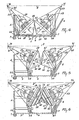
- the contact pressure during operation between, on the one hand, the conical friction surfaces 29 and 51 of the friction elements 28 and 52 and, on the other hand, the friction surface of the control rings 64 and 65 results in contact areas each of which having a major axis, since the materials employed will always behave somewhat elastically.
- the projection of the major axis of the contact area between the friction element 28 and the friction surface of the control ring 64 and the projection of the major axis of the contact between the friction element 50 and the friction surface of the control ring 65 intersect the main axis 8 at the same point (70, 71) as the centreline 27 of the rotary shaft 26 of the friction element 28 and the centreline 47 of the rotary shaft 46 of the friction element 50, respectively.
- the centrelines 23 and 43 of the pivotal shafts 24 and 44 of the arms 25 and 45 respectively also intersect the main axis 8 at the points 70, 71.
- the shape of the curved friction surfaces of the control rings 64 and 65 is designed so that these geometrical conditions are satisfied in any relative position of the control rings 64 and 65.
- the friction elements 28 and 50 roll along the friction surfaces of the control rings 64 and 65 and also one along the other. Owing to this rolling movement of the friction elements 28 and 50 the pinions 32 and 56 rigidly secured to the friction elements are rotated about the centrelines 27 and 47 respectively.
- the three pinions 34 and the three pinions 57 (operating as planetary wheels) drive, in turn, the central pinions or sunwheels 35 and 59 respectively.
- the sunwheel 35 transmits its rotation to the shaft 2 through the splines 16.
- the sunwheel 59 transmits its rotation through splines to the sleeve 36, which, in turn, is rotationally fastened by the splines 17 to the shaft 2. Therefore, the rolling movement of the friction elements 28 and 50 produces rotation of the output shaft 2.
- the projected major axis of the contact area between the friction element 28 and the friction surface of the control ring 64, the centreline 27 of the rotary shaft of the friction element 28, the centreline 23 of the pivotal shaft of the friction element 28 and the main axis 8 all intersect one another at the same point 70.
- This point has a fixed location with respect to the shaft 1.
- the projected major axis contact area between each of the friction elements 50 and the control ring 65, the centrelines 47 of the rotary shafts of the friction elements, the centrelines 43 of the associated pivotal shafts of the friction elements and the main axis 8 all intersect one another at the point 71.
- the location of the point of intersection 71 depends upon the setting of the control ring 64 with respect to the housing 3 and is variable along the main axis 8.
- the projected major axes of the contact areas between two friction elements 28 and 50 intersect the main axis 8 at right angles in any setting of the control ring 64. From the foregoing it will be apparent that the friction elements 28 and 50 will engage the control rings 64 and 65 by centrifugal forces.
- each friction element 28 and 50 support one another pairwise in an axial direction, a substantial part of these heavy axial loads on the bearings supporting the friction elements with respect to their shafts are avoided because each friction element directly absorbs the axial component of the contact pressure of the other friction element of the friction surface of its control ring so that these axial components will not be applied to the bearings of the friction elements.
- Figure 6 shows an embodiment of the friction elements 28 and 50, in which the friction surface 30 of the friction element 28 has a plurality of annular ridges on its curved surface.
- the ridges 72 are parallel to a plane perpendicular to the centreline 27 of the rotary shaft 26 of the friction element.
- the ridges 72 can engage annular grooves 73 in the friction surface 52 of the friction element 50.
- the distance between the ridges 72 on the friction surface 30 and the corresponding grooves 73 in the friction surface 52 is chosen so that in any relative position of the friction elements 28 and 50 at least one of the ridges 72 is in engagement with a groove 73.
- This disposition may be important for relatively fixing the three pairs of friction elements 28 and 50 during operation, particularly in the event of wear of the surfaces resulting from impact at the beginning or end of power transmission. Since an undesirable displacement between the friction elements 28 and 50, which would result in a non-symmetrical disposition, might produce a deviation from the desired oblong shape of the contact area between one of the friction elements and the associated control ring with respect to the geometrically correct location of this contact area (this deviation would, in general, be half the relative displacement of the friction elements themselves), such a fixing mode may be desirable under given conditions.
- the torque converter described above is capable of transferring a power of about 150 HP, substantially without mechanical loss, with a diameter of the cylindrical housing 6 of about 50 cms.
- Each of the friction elements should then have a weight of not more than about 3 kilogrammes.
- the output shaft 2 can be driven with a continuously variable speed in the range 115 to 575 rev/min.
Landscapes
- Engineering & Computer Science (AREA)
- General Engineering & Computer Science (AREA)
- Mechanical Engineering (AREA)
- Friction Gearing (AREA)
Claims (26)
Applications Claiming Priority (4)
| Application Number | Priority Date | Filing Date | Title |
|---|---|---|---|
| NL7810297A NL7810297A (nl) | 1978-10-13 | 1978-10-13 | Koppelomvormer. |
| NL7810297 | 1978-10-13 | ||
| NL7810296A NL7810296A (nl) | 1978-10-13 | 1978-10-13 | Koppelomvormer. |
| NL7810296 | 1978-10-13 |
Publications (2)
| Publication Number | Publication Date |
|---|---|
| EP0010329A1 EP0010329A1 (fr) | 1980-04-30 |
| EP0010329B1 true EP0010329B1 (fr) | 1982-08-11 |
Family
ID=26645455
Family Applications (1)
| Application Number | Title | Priority Date | Filing Date |
|---|---|---|---|
| EP79200581A Expired EP0010329B1 (fr) | 1978-10-13 | 1979-10-11 | Convertisseur de couple |
Country Status (3)
| Country | Link |
|---|---|
| US (1) | US4282774A (fr) |
| EP (1) | EP0010329B1 (fr) |
| DE (1) | DE2963547D1 (fr) |
Families Citing this family (7)
| Publication number | Priority date | Publication date | Assignee | Title |
|---|---|---|---|---|
| EP0087547B1 (fr) * | 1982-02-25 | 1986-09-03 | FIAT AUTO S.p.A. | Transmission épicycloidale continue de vitesse, comprenant des rouleaux planétaires à double conicité |
| WO1983003291A1 (fr) * | 1982-03-15 | 1983-09-29 | Chambers, Robert, O. | Jeu de roues d'engrenage ayant un mecanisme interne d'engrenage |
| US4609362A (en) * | 1983-07-05 | 1986-09-02 | The United States Of America As Represented By The Secretary Of The Navy | Non-soniferous power drive for underwater vehicles |
| NL9301646A (nl) * | 1993-09-23 | 1995-04-18 | Doornes Transmissie Bv | Traploos instelbare transmissie. |
| DE19804011A1 (de) * | 1998-02-02 | 1999-08-05 | Georg Albersinger | Stufenlos verstellbares Wälzgetriebe |
| JP2005307835A (ja) * | 2004-04-20 | 2005-11-04 | Toyota Industries Corp | 変速機付き圧縮機 |
| CN104776186A (zh) * | 2015-04-27 | 2015-07-15 | 姬志强 | 一种直接传动无级变速装置 |
Family Cites Families (17)
| Publication number | Priority date | Publication date | Assignee | Title |
|---|---|---|---|---|
| US1194107A (en) * | 1916-08-08 | Variable-speed-transmission mechanism | ||
| FR634915A (fr) * | 1927-05-24 | 1928-03-02 | Changement de vitesse à friction | |
| US1762199A (en) * | 1929-07-03 | 1930-06-10 | Hartford Special Machinery Co | Variable-speed transmission |
| US1938605A (en) * | 1932-01-07 | 1933-12-12 | August J Mottlau | Variable speed transmission |
| US2062901A (en) * | 1936-04-15 | 1936-12-01 | Louis A Graham | Variable speed transmission |
| US2686432A (en) * | 1949-10-28 | 1954-08-17 | Walter E Gudert | Mechanical infinitely variable speed transmission |
| US2680388A (en) * | 1951-04-30 | 1954-06-08 | Lazarowicz Gustaw | Variable speed power transmission |
| US2807964A (en) * | 1955-01-05 | 1957-10-01 | Hupp Corp | Automatic transmission |
| FR1152946A (fr) * | 1955-05-12 | 1958-02-27 | Transmission à rouleaux à friction dont les rouleaux sont disposés en une rangée de rouleaux coniques ou disposés les uns à côté des autres | |
| FR72565E (fr) * | 1957-12-09 | 1960-04-14 | Transmission à rouleaux à friction dont les rouleaux sont disposés en une rangéede rouleaux coniques ou disposés les uns à côté des autres | |
| AT210699B (de) * | 1958-05-30 | 1960-08-25 | Karl Maichen | Stufenloses Planetenreibradgetriebe |
| FR1205687A (fr) | 1958-07-22 | 1960-02-04 | Auxilec | Variateur continu de vitesse à galets coniques |
| US3241382A (en) * | 1963-10-15 | 1966-03-22 | Wescomb O Temple | Power transmission device |
| US3285083A (en) * | 1964-07-09 | 1966-11-15 | Silentbloc Australia Proprieta | Infinitely variable speed transmission apparatus |
| US3802295A (en) * | 1972-10-30 | 1974-04-09 | J Lemmens | Variable speed transmission |
| CA1053031A (fr) * | 1975-09-18 | 1979-04-24 | Textron Inc. | Transmission a variation du couple continue |
| JPS545164A (en) * | 1977-06-14 | 1979-01-16 | Shinpo Kogyo Kk | Friction-type stepless change gear |
-
1979
- 1979-10-11 DE DE7979200581T patent/DE2963547D1/de not_active Expired
- 1979-10-11 EP EP79200581A patent/EP0010329B1/fr not_active Expired
- 1979-10-11 US US06/083,637 patent/US4282774A/en not_active Expired - Lifetime
Also Published As
| Publication number | Publication date |
|---|---|
| US4282774A (en) | 1981-08-11 |
| DE2963547D1 (en) | 1982-10-07 |
| EP0010329A1 (fr) | 1980-04-30 |
Similar Documents
| Publication | Publication Date | Title |
|---|---|---|
| EP0004461A1 (fr) | Transmission à vitesse continûment variable | |
| GB1577335A (en) | Plunging universal joints | |
| US5443431A (en) | Differential with friction-enhancing wedge | |
| US4112780A (en) | Variable speed transmission device | |
| GB1592180A (en) | Skidsteering apparatus | |
| EP0010329B1 (fr) | Convertisseur de couple | |
| GB1597092A (en) | Homokinetic joint allowing a large angular displacement | |
| US4224840A (en) | Traction roller transmission | |
| GB1479765A (en) | Transmission device | |
| CA1161280A (fr) | Transmission automatique a changement de vitesse continu | |
| EP0038819B1 (fr) | Transmission a friction a variation continue | |
| US4694704A (en) | Infinitely variable traction roller transmission | |
| US2936638A (en) | Variable speed friction drive | |
| US4559841A (en) | Gear train having an internal gear mechanism | |
| EP0279127B1 (fr) | Joint universel télescopique à tripode | |
| US2709902A (en) | Universal joint drive | |
| US4392395A (en) | Infinitely variable transmission | |
| US4280369A (en) | Ball/ramp system for torque transmission | |
| EP0486191A1 (fr) | Variateur continue de vitesse à friction sans pivotement de contact | |
| CA1137335A (fr) | Element de traction sur transmissions a vitesses infiniment variables | |
| CA1066091A (fr) | Transmission a vitesse variable | |
| RU2179671C1 (ru) | Фрикционно-планетарный механизм с косой шайбой и бесступенчатая передача на его основе | |
| CA1149642A (fr) | Organe transmetteur de couple pour transmission motrices, et methode pour engendrer un effort de friction normal | |
| US4454782A (en) | Torque transmitting body for traction drive transmissions and normal friction force developing method | |
| US4694701A (en) | Radially oriented nutational traction drive transmission with large range of speed ratios |
Legal Events
| Date | Code | Title | Description |
|---|---|---|---|
| PUAI | Public reference made under article 153(3) epc to a published international application that has entered the european phase |
Free format text: ORIGINAL CODE: 0009012 |
|
| AK | Designated contracting states |
Designated state(s): DE FR GB NL |
|
| 17P | Request for examination filed |
Effective date: 19801020 |
|
| GRAA | (expected) grant |
Free format text: ORIGINAL CODE: 0009210 |
|
| AK | Designated contracting states |
Designated state(s): DE FR GB NL |
|
| REF | Corresponds to: |
Ref document number: 2963547 Country of ref document: DE Date of ref document: 19821007 |
|
| EN | Fr: translation not filed | ||
| PG25 | Lapsed in a contracting state [announced via postgrant information from national office to epo] |
Ref country code: DE Effective date: 19830701 |
|
| PGFP | Annual fee paid to national office [announced via postgrant information from national office to epo] |
Ref country code: FR Payment date: 19831027 Year of fee payment: 5 |
|
| REG | Reference to a national code |
Ref country code: FR Ref legal event code: DJ |
|
| REG | Reference to a national code |
Ref country code: FR Ref legal event code: PC |
|
| PG25 | Lapsed in a contracting state [announced via postgrant information from national office to epo] |
Ref country code: FR Free format text: LAPSE BECAUSE OF NON-PAYMENT OF DUE FEES Effective date: 19841027 |
|
| PGFP | Annual fee paid to national office [announced via postgrant information from national office to epo] |
Ref country code: NL Payment date: 19841031 Year of fee payment: 6 |
|
| PG25 | Lapsed in a contracting state [announced via postgrant information from national office to epo] |
Ref country code: NL Effective date: 19860501 |
|
| GBPC | Gb: european patent ceased through non-payment of renewal fee | ||
| NLV4 | Nl: lapsed or anulled due to non-payment of the annual fee | ||
| REG | Reference to a national code |
Ref country code: FR Ref legal event code: BR |
|
| PG25 | Lapsed in a contracting state [announced via postgrant information from national office to epo] |
Ref country code: GB Effective date: 19881118 |
|
| PLBE | No opposition filed within time limit |
Free format text: ORIGINAL CODE: 0009261 |
|
| STAA | Information on the status of an ep patent application or granted ep patent |
Free format text: STATUS: NO OPPOSITION FILED WITHIN TIME LIMIT |