EP0010363A1 - Imprägnierter Kondensator und seine Elektrodenfolie - Google Patents
Imprägnierter Kondensator und seine Elektrodenfolie Download PDFInfo
- Publication number
- EP0010363A1 EP0010363A1 EP79301966A EP79301966A EP0010363A1 EP 0010363 A1 EP0010363 A1 EP 0010363A1 EP 79301966 A EP79301966 A EP 79301966A EP 79301966 A EP79301966 A EP 79301966A EP 0010363 A1 EP0010363 A1 EP 0010363A1
- Authority
- EP
- European Patent Office
- Prior art keywords
- foil
- dimple
- roll
- dimples
- capacitor
- Prior art date
- Legal status (The legal status is an assumption and is not a legal conclusion. Google has not performed a legal analysis and makes no representation as to the accuracy of the status listed.)
- Granted
Links
- 239000011888 foil Substances 0.000 title claims abstract description 186
- 239000003990 capacitor Substances 0.000 title claims abstract description 129
- 238000005470 impregnation Methods 0.000 title description 18
- -1 polypropylene Polymers 0.000 claims abstract description 40
- 239000004743 Polypropylene Substances 0.000 claims abstract description 36
- 229920001155 polypropylene Polymers 0.000 claims abstract description 36
- 229910052782 aluminium Inorganic materials 0.000 claims abstract description 24
- XAGFODPZIPBFFR-UHFFFAOYSA-N aluminium Chemical compound [Al] XAGFODPZIPBFFR-UHFFFAOYSA-N 0.000 claims abstract description 24
- 239000012530 fluid Substances 0.000 claims description 58
- 238000000034 method Methods 0.000 claims description 30
- 230000008569 process Effects 0.000 claims description 27
- 238000004804 winding Methods 0.000 claims description 24
- 238000004049 embossing Methods 0.000 claims description 14
- 239000000463 material Substances 0.000 claims description 14
- 229920003002 synthetic resin Polymers 0.000 claims description 10
- 239000000057 synthetic resin Substances 0.000 claims description 10
- 238000004519 manufacturing process Methods 0.000 claims description 9
- 150000002148 esters Chemical class 0.000 claims description 5
- 229930195733 hydrocarbon Natural products 0.000 claims description 5
- 150000002430 hydrocarbons Chemical class 0.000 claims description 5
- 125000001997 phenyl group Chemical group [H]C1=C([H])C([H])=C(*)C([H])=C1[H] 0.000 claims description 5
- OTMSDBZUPAUEDD-UHFFFAOYSA-N Ethane Chemical compound CC OTMSDBZUPAUEDD-UHFFFAOYSA-N 0.000 claims description 3
- 229910000831 Steel Inorganic materials 0.000 claims description 3
- 238000012937 correction Methods 0.000 claims description 3
- 239000004033 plastic Substances 0.000 claims description 3
- 229920003023 plastic Polymers 0.000 claims description 3
- 239000010959 steel Substances 0.000 claims description 3
- 239000004215 Carbon black (E152) Substances 0.000 claims 3
- HKTCLPBBJDIBGF-UHFFFAOYSA-N 1-phenyl-2-propan-2-ylbenzene Chemical group CC(C)C1=CC=CC=C1C1=CC=CC=C1 HKTCLPBBJDIBGF-UHFFFAOYSA-N 0.000 claims 1
- 230000003993 interaction Effects 0.000 claims 1
- 229920005989 resin Polymers 0.000 claims 1
- 239000011347 resin Substances 0.000 claims 1
- 238000012360 testing method Methods 0.000 description 16
- 238000013461 design Methods 0.000 description 9
- 238000012986 modification Methods 0.000 description 9
- 230000004048 modification Effects 0.000 description 9
- 229910052751 metal Inorganic materials 0.000 description 8
- 239000002184 metal Substances 0.000 description 8
- 230000035515 penetration Effects 0.000 description 7
- 230000002596 correlated effect Effects 0.000 description 6
- 230000008961 swelling Effects 0.000 description 6
- 125000000217 alkyl group Chemical group 0.000 description 5
- 235000010290 biphenyl Nutrition 0.000 description 5
- 239000002131 composite material Substances 0.000 description 5
- 239000000203 mixture Substances 0.000 description 5
- 125000006850 spacer group Chemical group 0.000 description 5
- 230000003746 surface roughness Effects 0.000 description 5
- QTKIQLNGOKOPOE-UHFFFAOYSA-N 1,1'-biphenyl;propane Chemical group CCC.C1=CC=CC=C1C1=CC=CC=C1 QTKIQLNGOKOPOE-UHFFFAOYSA-N 0.000 description 4
- 238000005259 measurement Methods 0.000 description 4
- ZUOUZKKEUPVFJK-UHFFFAOYSA-N phenylbenzene Natural products C1=CC=CC=C1C1=CC=CC=C1 ZUOUZKKEUPVFJK-UHFFFAOYSA-N 0.000 description 4
- 230000008033 biological extinction Effects 0.000 description 3
- 230000000295 complement effect Effects 0.000 description 3
- 230000000694 effects Effects 0.000 description 3
- 229920001971 elastomer Polymers 0.000 description 3
- 238000005530 etching Methods 0.000 description 3
- 230000001788 irregular Effects 0.000 description 3
- 239000012466 permeate Substances 0.000 description 3
- 229920006389 polyphenyl polymer Polymers 0.000 description 3
- 230000000717 retained effect Effects 0.000 description 3
- 239000005060 rubber Substances 0.000 description 3
- 239000007787 solid Substances 0.000 description 3
- 150000001335 aliphatic alkanes Chemical class 0.000 description 2
- 230000008901 benefit Effects 0.000 description 2
- 239000004305 biphenyl Substances 0.000 description 2
- 150000004074 biphenyls Chemical class 0.000 description 2
- 238000010276 construction Methods 0.000 description 2
- 238000002788 crimping Methods 0.000 description 2
- 239000013078 crystal Substances 0.000 description 2
- 230000006872 improvement Effects 0.000 description 2
- 230000013011 mating Effects 0.000 description 2
- 238000005498 polishing Methods 0.000 description 2
- 230000003252 repetitive effect Effects 0.000 description 2
- 239000012858 resilient material Substances 0.000 description 2
- 238000007788 roughening Methods 0.000 description 2
- 229910000679 solder Inorganic materials 0.000 description 2
- LAXBNTIAOJWAOP-UHFFFAOYSA-N 2-chlorobiphenyl Chemical group ClC1=CC=CC=C1C1=CC=CC=C1 LAXBNTIAOJWAOP-UHFFFAOYSA-N 0.000 description 1
- 241000282979 Alces alces Species 0.000 description 1
- NLZUEZXRPGMBCV-UHFFFAOYSA-N Butylhydroxytoluene Chemical compound CC1=CC(C(C)(C)C)=C(O)C(C(C)(C)C)=C1 NLZUEZXRPGMBCV-UHFFFAOYSA-N 0.000 description 1
- 229920001875 Ebonite Polymers 0.000 description 1
- 230000005856 abnormality Effects 0.000 description 1
- 150000001346 alkyl aryl ethers Chemical class 0.000 description 1
- 150000004996 alkyl benzenes Chemical class 0.000 description 1
- 239000003963 antioxidant agent Substances 0.000 description 1
- 230000003078 antioxidant effect Effects 0.000 description 1
- 150000001491 aromatic compounds Chemical class 0.000 description 1
- 150000005840 aryl radicals Chemical class 0.000 description 1
- 230000004888 barrier function Effects 0.000 description 1
- 230000005540 biological transmission Effects 0.000 description 1
- 125000006267 biphenyl group Chemical group 0.000 description 1
- 125000004432 carbon atom Chemical group C* 0.000 description 1
- 238000005266 casting Methods 0.000 description 1
- 230000015556 catabolic process Effects 0.000 description 1
- 238000001311 chemical methods and process Methods 0.000 description 1
- 150000008422 chlorobenzenes Chemical class 0.000 description 1
- 239000011248 coating agent Substances 0.000 description 1
- 238000000576 coating method Methods 0.000 description 1
- 238000005520 cutting process Methods 0.000 description 1
- 230000003247 decreasing effect Effects 0.000 description 1
- 230000002950 deficient Effects 0.000 description 1
- 150000001987 diarylethers Chemical group 0.000 description 1
- 239000003989 dielectric material Substances 0.000 description 1
- 238000001035 drying Methods 0.000 description 1
- 239000007772 electrode material Substances 0.000 description 1
- 150000002118 epoxides Chemical class 0.000 description 1
- 238000011049 filling Methods 0.000 description 1
- 238000005429 filling process Methods 0.000 description 1
- 238000010297 mechanical methods and process Methods 0.000 description 1
- 239000007769 metal material Substances 0.000 description 1
- 150000002739 metals Chemical class 0.000 description 1
- SYSQUGFVNFXIIT-UHFFFAOYSA-N n-[4-(1,3-benzoxazol-2-yl)phenyl]-4-nitrobenzenesulfonamide Chemical class C1=CC([N+](=O)[O-])=CC=C1S(=O)(=O)NC1=CC=C(C=2OC3=CC=CC=C3N=2)C=C1 SYSQUGFVNFXIIT-UHFFFAOYSA-N 0.000 description 1
- UFWIBTONFRDIAS-UHFFFAOYSA-N naphthalene-acid Natural products C1=CC=CC2=CC=CC=C21 UFWIBTONFRDIAS-UHFFFAOYSA-N 0.000 description 1
- 238000012545 processing Methods 0.000 description 1
- 238000004080 punching Methods 0.000 description 1
- 238000013102 re-test Methods 0.000 description 1
- 238000005096 rolling process Methods 0.000 description 1
- 239000004576 sand Substances 0.000 description 1
- 238000002791 soaking Methods 0.000 description 1
- 239000011343 solid material Substances 0.000 description 1
- 230000006641 stabilisation Effects 0.000 description 1
- 238000011105 stabilization Methods 0.000 description 1
- 239000000126 substance Substances 0.000 description 1
- 230000002459 sustained effect Effects 0.000 description 1
- 238000001291 vacuum drying Methods 0.000 description 1
- XLYOFNOQVPJJNP-UHFFFAOYSA-N water Substances O XLYOFNOQVPJJNP-UHFFFAOYSA-N 0.000 description 1
Images

Classifications
-
- H—ELECTRICITY
- H01—ELECTRIC ELEMENTS
- H01G—CAPACITORS; CAPACITORS, RECTIFIERS, DETECTORS, SWITCHING DEVICES, LIGHT-SENSITIVE OR TEMPERATURE-SENSITIVE DEVICES OF THE ELECTROLYTIC TYPE
- H01G4/00—Fixed capacitors; Processes of their manufacture
- H01G4/002—Details
- H01G4/018—Dielectrics
- H01G4/20—Dielectrics using combinations of dielectrics from more than one of groups H01G4/02 - H01G4/06
- H01G4/22—Dielectrics using combinations of dielectrics from more than one of groups H01G4/02 - H01G4/06 impregnated
-
- H—ELECTRICITY
- H01—ELECTRIC ELEMENTS
- H01G—CAPACITORS; CAPACITORS, RECTIFIERS, DETECTORS, SWITCHING DEVICES, LIGHT-SENSITIVE OR TEMPERATURE-SENSITIVE DEVICES OF THE ELECTROLYTIC TYPE
- H01G13/00—Apparatus specially adapted for manufacturing capacitors; Processes specially adapted for manufacturing capacitors not provided for in groups H01G4/00 - H01G11/00
- H01G13/02—Machines for winding capacitors
Definitions
- This invention relates to improved capacitor grade aluminum foil and to an improved capacitor including .such, and more particularly to a dielectric fluid filled capacitor structure wherein solid synthetic resin dielectric . strips and foil electrode strips have mutually complementary roughened and patterned interface surfaces to stabilize their spaced relationship and to facilitate fluid penetration therebetween.
- Fluid impregnated capacitors made up of alternating electrode foil and synthetic resin film strips wound in a tight roll form have been difficult to impregnate with dielectric fluids because although a capacitor roll is wound with a certain degree of looseness, defined as space factor, the fluid must not only penetrate into.the roll from the ends thereof, but must also penetrate the interfaces between film strips which stick together, and between film and foil strips which also stick together.
- a number of solutions have been proposed which relate to complex impregnation cycles and roughening of the foil and/or film surfaces by various surface disfiguration methods, including mechanical and chemical processes such as foil embossing, abrading, and coating, and film etching.
- Roll 10 in a partly unrolled form.
- Roll 10 includes a pair of spaced metal foil strip electrodes 11 and 12 and intermediate polypropylene film strips 13 and 14. Additional polypropylene film strips 15 and 16 complete the roll so that pairs of polypropylene film strips are found between metal foil electrode strips,throughout the roll.
- Tap straps 17 and 18 are inserted into the roll 10 to lie ajdacent the electrode strips to serve as electrical connections for the electrodes.
- One or more capacitor rolls 10 are inserted into an appropriate casing, the casing is filled with a dielectric fluid and the fluid is caused to penetrate and permeate the roll to fill up the spaces between the windings of the roll as well as into the polypropylene material itself.
- One such capacitor 19 is shown in FIG. 2 wherein-a single roll 10 is included in a can or casing 20 filled with dielectric fluid 21 (not shown).
- Can 20 includes a pair of electrical terminals 22 and 23 to which taps 17 and 18 are connected.
- FIG. 3 is a capacitor to which this invention is more parttcularly applicable.
- capacitor 26 Includes a plurality of rolls 10 which may be arranged in an upper and lower row, as a two pack design, all of which are immersed in fluid 21. Casing 20 may exceed 65.0 cm in height, and the rolls 10 may be from about 10 inches (25.4 cm) to 12 inches (30.5 cm) in length. Rolls 10 also include taps 17 and 18 which are joined together electrically and to terminals 27 and 28. Where a single pack design is utilized, the rolls are referred to as wide rolls and may be about 60 cm or greater in length. Taps 17 and 18 may be eliminated by use of an exposed foil construction where each electrode foil projects from a respective end of the roll. The foil windings at each end are soldered together and then a connection is made to terminals 27 and 28.
- the fluid must enter through the roll ends 29 (FIG. 1) and 30 (FIG.3 ).
- the overlapping polypropylene film strip edges at the roll ends tend to seal together as well as seal to.the electrode strips and swell tightly with adjacent strips when absorbing fluid, thus.hindering the penetration of the fluid into the roll.
- Hazy film is the subject of a U.S. patent application, serial no. 686,832 assigned to the same assignee as the present invention, and, for example, U.K. Patent No. 1542671.
- Hazy film comprises polypropylene film obtained from a blown tube manufacturing process where temperatures and speeds are controlled in such a manner that a polypropylene stalk or tube emanating from an extruder has on its outer surface a continuous and coextensive uniform layer of predominately type III crystal structures, often referred to as ⁇ crystals. Subsequent insufflation of the stalk into a bubble form results in surface discontinuities or craters sometimes defied as surface fibrils extending completely over one surface of the film. These fibrils may extend as much as 2 to 3 microns from the base film thickness. As described, the Hazy film of this invention therefore has one surface quite roughened and the opposite surface may be denoted as smooth or shiny.
- Roughness may be measured by ASTM test D2457-70 or D10003 although a measurement which considers the open space in a rough surface (space factor) is preferred.
- This irregular surface texture on the capacitor film strips in rolls 10 provides a space factor in the form of fluid paths between a contiguous foil electrode and a dielectric strip, or between contiguous dielectric strips to facilitate the penetration of fluid.
- Modified forms of Hazy film may be obtained from other film processes including the draft and tentering process and film casting process. However, within the realm of this invention other surface roughened films may be employed provided their surface roughness and space factor characteristics are reasonably similar to those of Hazy film, although Hazy film is most preferred.
- Hazy film has not only a high degree of surface irregularity, but also a highly desirable high space factor.
- Space factor is a term describing the measured excess space for example between a measured volume of Hazy film strips superimposed on each other as compared with the measured volume of the same strips without any surface roughness, In other words, the roughness desired is related to a maximum peak to valley measurement over fewer peaks and valleys (which would give a high space factor and high impreg- nabilityl as compared to a maximum number of peaks and valleys of lesser dimensions which would give a lower space factor.
- surface roughness may be empirically correlated to space factor by measuring light transmission through the film, for example, as per ASTM D10003,.and the measurement obtained is in terms of haze.
- capacitor electrodes may be foils of various metals, aluminum fotl ts the principle electrode material presently employed. Ordinarily, these electrodes are about 0.20 to 0.24 mils thickness (5.0 to 6,1 microns) and are soft annealed aluminum. It has been known to roughen the surfaces of alumtnum electrodes in capacitor rolls to facilitate impregnation of the roll by deformation, etching, abrading, etc, U.S. Patent 3,746,953 is an example.
- This foil preferably comprises a soft annealed aluminum foil strip having a plurality of individual curvilinear surfaced dimple like projections and depressions from the plane of the foil, said projections and depressions being coterminous with the length and breadth of the useful foil surface in an electrical capacitor, said dimple-like projections being formed and spaced apart in a manner whereby there is a smooth essentially continuously curving foil surface leading from one dimple to an adjacent projection so that a point on the base of one dimple and a point on the adjacent base of a projection are essentially coincident.
- Fig. 4 there is illustrated a section of a foil strip electorde 11 showing an exaggerated embossed and raised pattern of dimple-like depressions 31 and proturberances 32 thereon.
- the raised dimple pattern is a pattern projecting equally and oppositely from both sides of the material and from the original thickness of the material so that the overall thickness is significantly greater than the original thickness.
- the dimple structure is more clearly illustrated in Fig: 5.
- Fig. 5 there is illustrated a cross-section, in line form, of the foil 11 of Fig. 4.
- the 'dimples are identical to each other, have an ovate like cross section, and extend about 0.0025 inches (about 12.7 microns) from each side of the center line of the foil strip.
- Each dimple has a base diameter of less than about 0.01 inch (about 0.254 microns) and the dimple or base centers are spaced about 0.02 inches apart (about 0.508 microns) as illustrated in FIG. 4.
- Each dimple may be described in preferred form as having a circular base and progressively decreasing horizontal circular cross sections terminating in a rounded or ovate form.
- the surfaces defining the dimples are smooth flowing curvilinear and continuous surfaces from one dimple, as a protuberance, to the next dimple as a depre; sion.
- the vertical cross section approximates an electrical sine wave form indicating that there are no sharp corners or interruptions in cur ture from the surface of one dimple to another.
- Other forms of curvilinear bases and cross sections may be employed so long as no sharp corners or ridges are present.
- the circular form described is preferred. This preference is based, in part, on the concept that the deformation of a foil strip to provide so many dimples may encompass a process which, in effect, smooths, polishes and work-hardens the foil to precondition it for capacitor utilization.
- the foil, as described, is referred to as a full dimple pattern foil. By this full dimple pattern, the total capacitor surface of the foil is involved in the pattern and there are no intermediate significantly undeformed areas.
- the pattern is described as 100/100 or 120/120 indicating that there are 200 or 240 dimples, respectively, for each . linear inch (2.54 cm) of electrode foil.
- the curvilinear surfaces are essentially continuous over the foil and not interrupted.
- the pattern may be extended to greater than 120/120, as conditions merit. It is preferred that each dimple, however, has the same general dimensions as an adjacent dimple so that a regular pattern is obtained with rows of dimples at right angles to each other.
- the full dimple pattern structure of this invention provides a maximum space between adjacent strips of aluminum foil and film dielectric strips with a minimum overall increase in space factor. This feature is attained through the unique structure of the foil.
- the dome structure of the dimples significantly increases the thickness of the aluminum foil from an original thickness of about 0.22 mil (0.5.5 ⁇ ) to approximately 1 mil (25.0 ⁇ ) This ts about five times the original thtckness, a total thickness which if incompressible or fixed could not be effectively utillzed in this invention. It is also a condition not ordinarily attained by means of etching, knurling or abrading an aluminum foil strtp.
- the mechanical.arch structure of dimples provides increasing or controlled resistance to crush- 'tng and dimple erasure or leveling when winding the foil under roll tension into a capacitor roll.
- it permits a substantial degree of desirable cushioning and leveling in the winding process so that in spite of its orignal thickness the final capacitor roll is within design tolerances.
- a range of thickness would be an increase from about 2 to 5 times the original thickness, with a preferred thickness being about 2-3 times the original thickness.
- the metal electrode of this invention becomes a variable or flexible thickness spacer in the capacitor roll winding process as well as in the final capacitor. This flexible or variable thickness is correlated to those imposed forces found in a capacitor manufacturing process so that a desired degree of thickness is retained in the final capacitor.
- the above concept indicates that the pattern on the foil should be correlated to the space factor desired in the capacitor, a high space factor permitting greater dimple height but a lesser number of dimples, and a lower space factor providing lesser dimple height, but more dimples per unit length.
- the important feature is that the sinusoidal pattern in both the length and width dimension and full foil involvement should be retained as close.as possible.
- the capacitor space factor as set forth in the examples and in the claims is that space factor as measured in a capacitor after full swelling of the polypropylene film by the impregnating fluid.
- the base measurement for the capacitor space factor is the space factor of the Hazy polypropylene film.
- the patterned foil space factor is Arbitrarily excluded.
- the space factor of a Hazy polypropylene film is the ratio of the theoretical, solid volume of a film strip as compared to its measured volume including a theoretical planar surface lying along the roughened surface. The ratio is given in percent of the solid volume so that a 10% space factor indicates a volume where the space is 10% df the solid material.
- the film space factor is then increased by an amount representing the swelling of the film by the fluid used at appropriate treat temperatures. The increased amount is correlated to a probability curve which accommodates the various tolerances in the manufacturing processes and materials, and a final design or capacitor space factor is determined which is larger than the measured film space factor as above described.
- Space factor in the capacitors of this invention is critical to accommodate all the differences in dimensional tolerances of the materials and the different temperature coefficients of expansion of the materials, and the swelling of the materials by the fluids. Space factor is necessary prior to fluid impregnation in order to have space available for the removal of water and other volatile materials when the capacitor is vacuum dried at elevated temperatures, as well as to meet the necessity of,having space through which the impregnating fluid passes to essentially completely impregnate the capacitor roll.
- Space factor should be uniform throughout the roll, i.e., there should be some minimum degree of space factor such as a mean or average space factor throughout the roll, and this space factor should be preserved and controlled throughout the winding process, and in the flattening process to flatten the capacitor as illustrated in FIG. 1.
- the combination of patterned foil and Hazy film is a means to more favorably utilize the space factor of the Hazy film, and to adjustably control space factor in the capacitors as described in this invention.
- the amount of space factor obtainable from presently available Hazy polypropylene films i.e., from about 3.0% to about 30%, is generally insufficient or otherwise undesirable to serve as the total space factor requirement in, for example, power capacitors, and if available in the film is expected to:be somewhat variable in the capacitor manufacturing process because of film swelling,
- the roughness on polypropylene film may not be entirely uniform and certain areas may have high roughness and others low roughness, a condition not correlated with variances in film and foil thickness and contributes to the problem of attaining a uniform space factor of some satisfactory degree throughout the capacitor roll.
- the complementary space factor control means is therefore the full dimple pattern foil of this invention whether or not there is a sufficient amount of space factor already present in the polypropylene film strips.
- the patterned foil serves as an adjustable cushioning means to provide the desired degree of space factor uniformly throughout the roll.
- the dimple structure requires an ever increasing force for flattening because of its unperforated dome structure and therefore adjusts itself to varying pressures or forces throughout the roll and in the roll winding process to retain the integrity of the design space factor. It is compressibly deformable and area selective over even a single dome, and more importantly, the total capacitor area of the foil is included in the pattern. This means that each dome supports the film so that the film does not touch the foil between domes to reduce the space factor or block fluid penetration,
- the Hazy film and full dimple pattern foil may be wound into a capacitor roll in various arrangements.
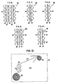
- One preferred arrangement uses only Hazy film as the dielectric material strips 13 through 16 between the foil electrodes 11 and 12. Such an arrangement is shown tn FIG. 6 in an exaggerated manner with the film and foil strips in spaced relation.
- the composite 33 comprises a pair of patterned or dimpled foils 34 and 35 and two intermediate Hazy film strips 36 and 37.
- one surface is usually quite smooth and shiny and the other surface ts referred to as a rough or matte surface.
- the foil . rolling operation involves passing two superimposed foil strips between the rolls and the surface between strips becomes different, . t.e.. rougher than the surface adjacent the rolls.
- the matte surface actually improves impregnation because of the additional space factor caused by the matte surface. Consequently, as a further aid to impregnation the aluminum foils are positioned such that the smooth or shiny surface is adjacent the rough surface of the Hazy film. This is referred to as a smooth to rough relationship.
- Hazy film strips may have the required surface discontinuities or roughness on one or both sides.
- the Hazy film as described in detail herein has but one surface which is rough. In this latter event when two polypropylene film strips are utilized, they are arranged in what is also referred to as a rough surface to a smooth surface relationship. In this manner each electrode foil strip has a smooth surface which is adjacent a rough surface of a Hazy film strip throughout the roll which facilitates more uniform impregnation of the roll.
- FIG. 7 A further modification of the embodiment of FIG. 6 is illustrated in FIG. 7.
- the composite 38 comprises a pair of Hazy film strips 36 and 37 which are arranged in rough to rough surface relationship.
- one or both rough surfaces of the electrode foil strips may be adjacent a smooth film strip surface although it is preferred to have one reversed from the other,
- the impregnating fluid is caused to permeate the rough surface areas between the film strips and then to proceed laterally through the film strips into the areas between the film strips and the foil strips. Fluid also permeates this area from the roll ends along the electrode foil surfaces.
- FIG. 8 An additional modification is illustrated in FIG. 8.
- the composite 39 comprises a pair of dimpled electrode foils 34 and 35 separated by a pair of Hazy film strips 36 and 37 which are arranged in smooth to smooth surface relationship.
- the arrangement of the smooth and rough electrode foil strip surfaces is relatively unimportant although it is preferred to have one reversed with respect to the other.
- the composite 40 comprises a pair of dimpled foils 34 and 35 separated by three Hazy film strips 36, 37 and 41.
- the film strips are all arranged in smooth to rough relationship as a preferred embodiment although there could be a mix of relationships.
- the electrode foil strips are arranged with a smooth foil surface adjacent. a rough surface of a film strip.
- the use of three film strips of FIG. 9 instead of two film strips of FIG. 6 may provide an additional advantage of a higher dielectric strength capacitor. Obviously more than three film strips may be employed as well as a single film strip.
- Electrode foil edges are usually referred to as sharp edged, a condition obtained when the foils are slit to a given width. This slitting is usually accomplished with a knife edge and the resultant electrode foil edge is sharp and sometimes irregular because of burr like projections which become the sites for the commencement of corona.
- a high voltage stress field is set up between electrode foil strips 34 and 35 at the roll ends 29 and 30, and any sharp edges or other discontinuities cause or support corona inception.
- FIG, 10 represents an embodiment which minimizes these high stress effects.
- the composite 42 comprises a wider electrode strip 43 and a narrower electrode foil strip 44 which are positioned in opposed axial relationship to each other, and the electrode foils are sometimes referred to as an upper electrode foil 43 and a lower electrode foil 44.
- the measured distance between the opposed electrode foil edges is increased.
- a narrower electrode causes a higher voltage stress in the area of the narrower electrode edge.
- this narrower electrode foil 44 has a folded edge 45 running throughout the roll. This folded edge 45 presents a smooth rounded surface to the high stress area and reduces the field stress at the rounded surface.
- the folded edge reduces the fluid film between the rolled edge and the adjacent polypropylene film strip, and accordingly reduces the likelihood of breakdown of lower dielectric constant fluid in this area,
- the foil electrode When folding an electrode foil at its edges it is important that the foil electrode also be folded at its beginning edge width and its terminating edge width or other means be employed to reduce the stress at those locations.
- a folded edge between about 0.125 inch (0.3175 cml and 0.5 inch (0.127 cm) will provide satisfactory results, and a range between 0.25 inch (0.635 cm) and 0.375 inch (0.95 cm) is preferred.
- An additional degree of space factor may be used to accommodate the folded edge. Best results are attained in this invention, with or without a folded electrode foil, when the final space factor is equal to or greater than an amount which will permit total and unrestricted swelling of the polypropylene film by the fluid in the capacitor.
- capacitor fluids may be effectively employed in this invention. Included are esters, hydrocarbons, and synthetic fluids such as the alkanes and biphenyls.
- the dielectric constant of these fluids may vary from about 2.5 to greater than about 5.
- the stress on the dielectric system is shared in proportion to the dielectric constants of the materials. Higher dielectric constant fluids shift more stress to the film, with a dielectric constant of polypropylene film of about 2.5, the lower dielectric constant fluids will be more highly stressed, and corona conditions at the roll edges may be worsened.
- alkyl benzene alkyl naphthalene, alkyl biphenyl, alkyl polyphenyl, alkylaryl ethers and alkyl substituted derivatives thereof, diaryl alkanes and alkyl substituted derivatives thereof, and diaryl ethers and alkyl substituted derivatives thereof, wherein said alkyl groups and alkanes have from 1 to about 20 carbon atoms, said aryl radicals are phenyl, napthyl, biphenyl, or polyphenyl, and said polyphenyls include from 3 to about 5 phenyl groups.
- diaryl alkane phenyl zylyl ethane
- PXE Nisseki Condenser oil S
- MIPB monoisopropyl biphenyl
- Monoisopropyl btpbenyl is commerctally available from Monsanto U.S., and others, as are various mixtures of mono di and other t s opropyl biphenyls,
- dielectric constant fluids include the chlorobenzenes, chlorodiphenyl oxides, and the mixtures of esters and chlorinated aromatic compounds.
- Impregnation of the capacitors of this invention may follow the usual practices associated with polypropylene film capacitors, for example, as disclosed and claimed in U.S. Patent 3,363,156.
- the capacitors may be placed in an oven and their temperatures elevated into a range between about 40°C and 100°C, and preferably between about 60 to 90°C for as much as 40 hours.
- the capacitor space factor used were in the range of from about 5% to about 8%.
- Hazy film roughness varied from about 10% to 30% space factor of the polypropylene film only.
- the fluids used were PXE (Fluid A) whtch was purchased from Nippon Chemical Company as Nisseki Condenser Oil S and contained about 97% phenyl zylyl ethane with the balance a mixture of isomers, and MIPB (Fluid B) which was purchased from Tanatex Company as Sure-Sol 250.
- the fluid was carefully refined to high purity and about 0.6 - 0.8% by weight of an epoxide such as ERL 4221 (commercially available from Union Carbide Company U.S.) and from about 0.01% to 0.10% by weight of an antioxidant material such as 2, 6-di-t-butyl-p-cresol were added thereto.
- ERL 4221 commercially available from Union Carbide Company U.S.
- an antioxidant material such as 2, 6-di-t-butyl-p-cresol
- capacitor rolls were 10.62 inches (26.97 cm) in length and comprised patterned aluminum foil electrodes of about 0.22 mil (5.6 micron) thickness with 100 dimples 50/50 per inch (2.54 cm) and two sheets of Hazy polypropylene film having about 10% to 3Q% space factor, one strip having a thickness of 0.70 mil (18 microns) and the other 1.0 mil (25.4 microns).
- Each capacitor was on the order of about 26 inches (66.0 cm) in height.
- the assembled capacitors were oven dried at a temperature in the range of 85°C to 100°C and a vacuum of less than 60 microns Hg. for about 26 hours.
- the capacitors were then allowed to cool to the range from about 50° to 80° C, and the impregnating fluid at a temperature of about 40° to 50° C was introduced into the capacitor under vacuum.
- the capacitors are placed 1n an oven and the temperature raised to from about 65° C to 85° C.
- the capacitors were left to soak in the oven for about 20 hours after which temperature is reduced to room temperature. This soaking was repeated a second time for an additional 20 hours. Thereafter the capacitors were brought to room temperature, sealed and given certain electrical tests,
- DIV is discharge inception voltage also known as corona start voltage, and the values given are the averages of three readings.
- DEV is discharge extinction voltage, also known as corona extinction voltage.
- Dissipation factor is %DF or tan ⁇ (loss angle) and is given as a watts loss percentage. The results show repetitive excellent capacitors as follows; albeit that the design and test criteria of these capacitors are inordinately severe.
- a further group of seven capacitors were made in accordance with the foregoing Example I, using a roll width of 22.5 inches (57.15 cm).
- the dielectric thickness was one-sheet of 0.7 mil (18 micron) and one sheet of 1.0 mil (25.4 micron).
- These capacitors were rated 52 ⁇ f and 75 KVAR, with 1990 volts on the dielectric system across the foils, These capacitors were put on a life test at voltages ranging from 2350 to 3600 volts and temperatures ranging from room temperature to 70° C. All capacitors so tested survived in excess of 500 hours at the higher than rated voltages thus showing the improved capabilities of the dielectric system.
- Item #6 was a wide roll 22.5 inches (57.15 cm). The others were 11.25 inches (28.75 cm).
- the pad voltage i.e., the voltage across the electrode foils ranged from 1800 to 19 9 0 volts.
- the dielectric thickness between the electrode foils ranged from 1.5 mil thickness (38 ⁇ ) to 1.7 mil thickness (43 ⁇ ).
- the overall space factor for the total capacitor roll design was in the range of 20% to 30% before impregnation. The results show repetitiveness and certainty of the capacitors made in accordance with the present invention.
- Example II Several capacitors were made up along the lines of those in Example I, The capacitors had rolls of 11.25 inches (28,75 cm) in length and 4 ⁇ f capacity. The capacitors were rated at 1990 volts across the foils. As per FIG. 8 one inside foil had each edge folded over for 0.375 inch (0.95 cm). Electrical tests on these capacitors indicate a marked increase in DIV and DEV values as compared to unfolded designs.
- capacitor units were made up of 15 inch (38.1 cm) rolls with patterned foil having 120/120 dimples per inch as described with respect to FIG. 11. Capacitor space factor was between 5% and 10%. The rolls were designed for 1670 volts. One sheet of 0.65 mil film (16.5 ⁇ ) with 5% to 10% space factor and one sheet of 0.7 mil film (17.7 ⁇ ) with 5% to 10% space factor were used in the dielectric system as illustrated in FIGS. 3, 5 and 6. Impregnation followed the practices of Example I.
- the combination moderates the impregnation parameters which have become so severe for all film capacitors, and provides a structure widely adaptable to various impregnation processes including those of the manifold fill and flood fill kinds.
- Polypropylene film, as well .as other synthetic resin films may be easily produced with some degree of surface roughness less than or exceeding the preferred Hazy film of this invention, for example, less than about 5.0%.
- the pattern foil of this invention will provide its unique spacer results over the total range of surface roughness of the synthetic resin film from about 5.0% to greater than 30.0%.
- the space factors of the dimpled foil may be correlated with the space factors of the film in a higher to lower relationship or lower to higher, as the case may be.
- the preferred ranges are from about 5.0% to 30.0% space factor for the film, and a foil thickness of about 2 to about 5 times the original thickness.
- Examination of the full dimple pattern foil removed from assembled capacitors shows areas of minimum and few areas of maximum thickness indicating that the foil conforms to the available space and pressures where the spaces are due to haze variations, mismatched tolerances, or uneven winding. Such examinations also indicate that the smaller dimples, with a greater number per inch are quite resistant to erasure and persevere to a high degree during the manufacturing process. Examination has also shown that excessive erasure indicates more dimple height than necessary. Consequently, dimple densities above about 100/100 are preferred. Most of the capacitors in the foregoing examples were high voltage power factor correction capacitors.
- Such capacitors may be rated above about 600 Volts AC to above about 13,800 volts AC, and their dielectric systems are under a high voltage stress. These capacitors are rated in KVAR (kilovolt ampere reactance) from about 50 KVAR to 400 KVAR and above. It ts in these capacitors that the present invention is most applicable and desirable.
- KVAR kilovolt ampere reactance
- Hazy film While it is eminently desirable to use Hazy film in this invention because of the assuredness it lends to the space factor it provides, a satisfactory all film capacitor can be produced solely with the full dimple pattern foil of this invention, particularly the narrow width roll capacitors. However, there are instances where it would appear that either the patterned foil of this invention or the Hazy film will provide improved results. Their use together sometimes masks the contribution of one over the other, which, as before mentioned might be attributable to their complementary functions, The following Examples provide some indication of the individual contributions of patterned foil and Hazy film.
- the capacitor construction and treatment were similar to those of Example I except that.the capacitor rolls were of narrow design 10.62 inches wide (26,9 mm) and relatively smooth film, e.g., low space factor (LS) are included.
- High space factor Hazy film (HS) had an average space factor of about 20%.
- Capacitor space factor was about 5%.
- the voltage rating of the dielectric was moderate, i.e., about 1200 volts.
- DC Direct Current
- AC Alternating Current
- Vr is rated voltage.
- the capacitors were rated at 7960 volts and 200 KVAR.
- the dimple or mound shape of the depressions and projections of the patterned foil of this invention utilize smooth flowing surfaces defining geometric ovate shapes which are extremely resistant to total deformation or crushing.
- dimples project equidistantly from both sides of the plane of the foil and form a geometric or regular and repeating pattern of equidistantly spaced dimples and rows as illustrated.
- the pattern is continuous and coterminous with the active foil surface in a capacitor.
- the use of the dimple pattern provides an added safety factor to the capacitors of this invention and a more reliant capacitor with respect to many minor abnormalities which may occur in capacitor operation.
- DC dielectric tests indicate an increased dielectric strength.
- the dimpling process is'carried out on the winding machine used to wind the capacitor rolls.
- the major advantage of this procedure is that it obviates the necessity of rewinding the patterned foil on a roll for subsequent winding into a capacitor roll.
- Such winding and rewinding exposes the dimples to potential damage, principally by crushing.
- the practice of using foil tension to drive the embossing rolls lends consistency and uniformity to the dimples and the pattern.
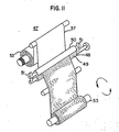
- the improved foil of this invention comprises a combination of deforming the full area of the foil and polishing or physically working the foil in selected areas which are coterminous over the foil surface, This improved foil may be produced in two more important processes which may be described with reference to FIGS. 11 and 12. In both instances an aluminum foil, U.S. Grade 1143 is used. This is a commercial designation of a soft annealed foil of 90.43+% purity.
- a capacitor roll winding machine 46 has suitably mounted thereon an embossing apparatus 47.
- a roll 48 is a steel roll having on its surface 49 a protruding dimple pattern containing the desired number of dimples per inch, preferably above about 100.
- Each dimple structure is of the same general structure as described with respect to the dimples of FIGS. 4 and 5 and all dimple heights are preferably the same.
- a second roll 50 is mounted on machine 46 in parallel relationship with roll 48.
- the outer surface of roll 50 is a hard but resilient material. This material may be a plastic or rubber like material and excellent results have been obtained with a hard rubber of about 60-80 durometer hardness.
- Roll 50 is biased against embossing roll 48 by means of suitable biasing or spring means 51.
- the aluminum foil 37 is pulled from a supply roll 52, and from between rolls 48 and 50 by the driver or capacitor winding roll 53, Other supply rolls deliver the other foil electrode and polypropylene dielectric strips to the capacitor roll 53.
- the depth of penetration of the protruding dimple of the embossing roller 49 into the rubber material of roll 50 falls in the range of from about 0.2 mil (5.0 ⁇ ) to about 1.0 mil. (25.4 ⁇ ). Consequently when starting with an aluminum foil thickness of from about 5.0 to 6.0 microns thickness, the final thickness of the embossed foil 37 is in the range of from about 2-5 times the original thickness of the aluminum foil.
- the embossed pattern which is impressed in the foil by this process is, in cross section, a sinusoidal pattern as illustrated in FIG. 5 in that the individual dimples are close to each other, press into the resilient roll surface to provide a rounded dimple tip, and the resilient material of the roll 50 is pressed up slightly into the area between adjacent dimples.
- the dimple height may be on the order of 50,0 ⁇ or more yet the penetration is limited to a fraction thereof. Consequently the embossing process alters the . original plane of the foil and a dimple protuberant is also generated on the side of the foil opposite the raised dimple pattern surface.
- the foil of this invention is defined as preconditioned foil because of the working and polishing of essentially the total foil surface, and in particular, the working and hardening of the dimple tips which press into the polypropylene film dielectric.
- tests indicate that a dimple concentration of 120/120,dimples per inch foil, together with the FIG.11 process is superior to lesser dimple concentration and the FIG.12 process in many respects. and is thus preferred.
- a preferred range of dimples starts above about 100/100 with an upper limit being the upper practical limitations of foil working, preserving distinct patterns maintaining a desirable depth of the pattern. Ordinarily this upper limit is about 500/500 dimples per inch.
- the overall thickness of the finished foil may be somewhat less than two times the original thickness. However, by changing roll winding techniques and tension, the resilient spacer concept is preserved.
- Apparatus 54 comprises a pair of embossing rolls 55 and 56 which are mounted for rotation on machine 46.
- Each roll surface is made of steel and is precision etched or engraved to provide mound- like projections thereon.
- either or both rolls may be of non metallic materials such as hardened plastics or rubbers.
- the roll surfaces precisely assembled with appropriate adjustment devices, are brought into mating engagement with each other so that the projections of one roll interfit between projections on the mating roll. External gearing couples the rolls to each other to maintain alignment.
- the roll projections defined mound like projections slightly in mesh with the same projections on the opposite roll.
- the rolls may be adjustable to vary their spaced apart distance to provide a dimple structure in the foil of about 0.0025 inches (about 63.5 microns) from the top of a dimple to the plane of the foil. In the adjustment of the rolls 55 and &6 there is a clearance which is sitnificantly greater than the foil thickness so that only a part of a dimple on the roll protrudes into the foil.
- the FIG. 12 apparatus does not provide the kind of preconditioning obtained from the FIG. 11 process because the dimple tips are not engaged on the outer surface by an opposing surface by an opposing surface which would work, smooth, and polish the metal.
Landscapes
- Engineering & Computer Science (AREA)
- Power Engineering (AREA)
- Manufacturing & Machinery (AREA)
- Microelectronics & Electronic Packaging (AREA)
- Fixed Capacitors And Capacitor Manufacturing Machines (AREA)
Applications Claiming Priority (6)
| Application Number | Priority Date | Filing Date | Title |
|---|---|---|---|
| US95238478A | 1978-10-18 | 1978-10-18 | |
| US952384 | 1978-10-18 | ||
| US952947 | 1978-10-19 | ||
| US05/952,947 US4228481A (en) | 1978-10-19 | 1978-10-19 | Capacitor with embossed foil electrode |
| US47425 | 1979-06-11 | ||
| US06/047,425 US4348712A (en) | 1978-10-18 | 1979-06-11 | Capacitor with embossed electrodes |
Publications (2)
| Publication Number | Publication Date |
|---|---|
| EP0010363A1 true EP0010363A1 (de) | 1980-04-30 |
| EP0010363B1 EP0010363B1 (de) | 1984-01-18 |
Family
ID=27367114
Family Applications (1)
| Application Number | Title | Priority Date | Filing Date |
|---|---|---|---|
| EP79301966A Expired EP0010363B1 (de) | 1978-10-18 | 1979-09-21 | Imprägnierter Kondensator und seine Elektrodenfolie |
Country Status (9)
| Country | Link |
|---|---|
| EP (1) | EP0010363B1 (de) |
| AT (1) | AT380749B (de) |
| AU (1) | AU532876B2 (de) |
| BR (1) | BR7906822A (de) |
| DE (1) | DE2966556D1 (de) |
| ES (1) | ES485169A0 (de) |
| FI (1) | FI72620C (de) |
| IL (1) | IL58310A (de) |
| MX (1) | MX147833A (de) |
Cited By (7)
| Publication number | Priority date | Publication date | Assignee | Title |
|---|---|---|---|---|
| US4439812A (en) * | 1981-11-02 | 1984-03-27 | General Electric Company | Impregnated capacitor foil |
| EP0045397A3 (en) * | 1980-08-01 | 1984-03-28 | Ero-Starkstrom Kondensatoren Gmbh | Impregnated wound capacitor |
| FR2536204A1 (fr) * | 1982-11-16 | 1984-05-18 | Europ Composants Electron | Condensateur electrique impregne |
| EP0063297B1 (de) * | 1981-04-16 | 1985-08-14 | Bayer Ag | Imprägniermittel und seine Verwendung |
| EP0072458B1 (de) * | 1981-08-18 | 1988-07-27 | Westinghouse Electric Corporation | Mehrfachleistungskondensator, dessen Dielektrikum wesentlich aus einem Kunststoffilm besteht |
| EP1482523A1 (de) * | 2003-05-27 | 2004-12-01 | Shin-Etsu Film Co., Ltd. | Öl-imprägnierter Folienkondensator und Verfahren zu dessen Herstellung |
| CN114846568A (zh) * | 2019-12-13 | 2022-08-02 | 京瓷株式会社 | 电介质薄膜、使用该电介质薄膜的薄膜电容器、连结型电容器、逆变器及电动车辆 |
Citations (6)
| Publication number | Priority date | Publication date | Assignee | Title |
|---|---|---|---|---|
| US1770851A (en) * | 1929-11-29 | 1930-07-15 | Gen Electric | Fluid-filled electric cable |
| GB1250450A (de) * | 1967-10-10 | 1971-10-20 | ||
| US3831234A (en) * | 1972-05-19 | 1974-08-27 | Mc Graw Edison Co | Method of manufacturing an electrical capacitor |
| FR2275860A1 (fr) * | 1974-06-20 | 1976-01-16 | Matsushita Electric Industrial Co Ltd | Dispositif electrique impregne d'huile |
| DE2548339A1 (de) * | 1974-11-01 | 1976-05-06 | Gen Electric | Elektrischer kondensator |
| FR2395576A1 (fr) * | 1977-06-24 | 1979-01-19 | Westinghouse Electric Corp | Dispositif contenant un liquide dielectrique |
-
1979
- 1979-09-21 DE DE7979301966T patent/DE2966556D1/de not_active Expired
- 1979-09-21 EP EP79301966A patent/EP0010363B1/de not_active Expired
- 1979-09-25 IL IL58310A patent/IL58310A/xx not_active IP Right Cessation
- 1979-09-27 AU AU51266/79A patent/AU532876B2/en not_active Ceased
- 1979-10-08 FI FI793112A patent/FI72620C/fi not_active IP Right Cessation
- 1979-10-17 AT AT0676579A patent/AT380749B/de not_active IP Right Cessation
- 1979-10-18 ES ES485169A patent/ES485169A0/es active Granted
- 1979-10-18 MX MX179681A patent/MX147833A/es unknown
- 1979-10-23 BR BR7906822A patent/BR7906822A/pt not_active IP Right Cessation
Patent Citations (6)
| Publication number | Priority date | Publication date | Assignee | Title |
|---|---|---|---|---|
| US1770851A (en) * | 1929-11-29 | 1930-07-15 | Gen Electric | Fluid-filled electric cable |
| GB1250450A (de) * | 1967-10-10 | 1971-10-20 | ||
| US3831234A (en) * | 1972-05-19 | 1974-08-27 | Mc Graw Edison Co | Method of manufacturing an electrical capacitor |
| FR2275860A1 (fr) * | 1974-06-20 | 1976-01-16 | Matsushita Electric Industrial Co Ltd | Dispositif electrique impregne d'huile |
| DE2548339A1 (de) * | 1974-11-01 | 1976-05-06 | Gen Electric | Elektrischer kondensator |
| FR2395576A1 (fr) * | 1977-06-24 | 1979-01-19 | Westinghouse Electric Corp | Dispositif contenant un liquide dielectrique |
Cited By (7)
| Publication number | Priority date | Publication date | Assignee | Title |
|---|---|---|---|---|
| EP0045397A3 (en) * | 1980-08-01 | 1984-03-28 | Ero-Starkstrom Kondensatoren Gmbh | Impregnated wound capacitor |
| EP0063297B1 (de) * | 1981-04-16 | 1985-08-14 | Bayer Ag | Imprägniermittel und seine Verwendung |
| EP0072458B1 (de) * | 1981-08-18 | 1988-07-27 | Westinghouse Electric Corporation | Mehrfachleistungskondensator, dessen Dielektrikum wesentlich aus einem Kunststoffilm besteht |
| US4439812A (en) * | 1981-11-02 | 1984-03-27 | General Electric Company | Impregnated capacitor foil |
| FR2536204A1 (fr) * | 1982-11-16 | 1984-05-18 | Europ Composants Electron | Condensateur electrique impregne |
| EP1482523A1 (de) * | 2003-05-27 | 2004-12-01 | Shin-Etsu Film Co., Ltd. | Öl-imprägnierter Folienkondensator und Verfahren zu dessen Herstellung |
| CN114846568A (zh) * | 2019-12-13 | 2022-08-02 | 京瓷株式会社 | 电介质薄膜、使用该电介质薄膜的薄膜电容器、连结型电容器、逆变器及电动车辆 |
Also Published As
| Publication number | Publication date |
|---|---|
| FI72620B (fi) | 1987-02-27 |
| AU532876B2 (en) | 1983-10-20 |
| FI793112A7 (fi) | 1980-04-19 |
| ATA676579A (de) | 1985-11-15 |
| ES8104629A1 (es) | 1981-04-16 |
| EP0010363B1 (de) | 1984-01-18 |
| MX147833A (es) | 1983-01-19 |
| IL58310A0 (en) | 1979-12-30 |
| AT380749B (de) | 1986-06-25 |
| DE2966556D1 (en) | 1984-02-23 |
| BR7906822A (pt) | 1980-06-17 |
| FI72620C (fi) | 1987-06-08 |
| ES485169A0 (es) | 1981-04-16 |
| AU5126679A (en) | 1980-04-24 |
| IL58310A (en) | 1982-05-31 |
Similar Documents
| Publication | Publication Date | Title |
|---|---|---|
| US4228481A (en) | Capacitor with embossed foil electrode | |
| US4348712A (en) | Capacitor with embossed electrodes | |
| EP0144560B1 (de) | Polyolefinisches Isolationspapierlaminat und Verfahren zur Herstellung desselben und elektrisches Zufuhrkabel | |
| EP0010363A1 (de) | Imprägnierter Kondensator und seine Elektrodenfolie | |
| JPH0463483B2 (de) | ||
| EP0043638B1 (de) | Kondensatorelektrode mit Randbedeckung | |
| JPH0357606B2 (de) | ||
| US2130532A (en) | Electrical condenser | |
| CA1147033A (en) | Impregnation capacitor | |
| JP7554599B2 (ja) | アルミニウム電解コンデンサ用セパレータ及びアルミニウム電解コンデンサ | |
| US4255381A (en) | Textured surface polypropylene film | |
| CA1053339A (en) | Capacitor having a hazy polypropylene film | |
| US4229777A (en) | High voltage dual dielectric capacitor roll | |
| CN117730386A (zh) | 电解电容器用电极箔、电解电容器以及电解电容器用电极箔的制造方法 | |
| JPH04378B2 (de) | ||
| DE1811776A1 (de) | Elektrischer Kondensator | |
| CA1180071A (en) | Impregnated capacitor foil | |
| KR830000929Y1 (ko) | 캐퍼시터 | |
| AT391960B (de) | Elektrischer kondensator | |
| EP0497456A1 (de) | Kapazitätsstruktur in Serienschaltung | |
| EP0141656B1 (de) | Imprägnierter Kondensator | |
| KR870003124Y1 (ko) | 콘 덴 서 | |
| US2288157A (en) | Dry electrolytic capacitor and spacing means therefor | |
| EP0421040A1 (de) | Metallisierte dielektrische Kunststoffilme, insbesondere für Elektroden von Kondensatoren | |
| KR830000288Y1 (ko) | 전기응력 용량을 개선시킨 콘덴서 |
Legal Events
| Date | Code | Title | Description |
|---|---|---|---|
| PUAI | Public reference made under article 153(3) epc to a published international application that has entered the european phase |
Free format text: ORIGINAL CODE: 0009012 |
|
| AK | Designated contracting states |
Designated state(s): BE CH DE FR GB IT SE |
|
| 17P | Request for examination filed | ||
| ITF | It: translation for a ep patent filed | ||
| GRAA | (expected) grant |
Free format text: ORIGINAL CODE: 0009210 |
|
| AK | Designated contracting states |
Designated state(s): BE CH DE FR GB IT SE |
|
| PG25 | Lapsed in a contracting state [announced via postgrant information from national office to epo] |
Ref country code: BE Effective date: 19840118 |
|
| REF | Corresponds to: |
Ref document number: 2966556 Country of ref document: DE Date of ref document: 19840223 |
|
| ET | Fr: translation filed | ||
| PLBE | No opposition filed within time limit |
Free format text: ORIGINAL CODE: 0009261 |
|
| STAA | Information on the status of an ep patent application or granted ep patent |
Free format text: STATUS: NO OPPOSITION FILED WITHIN TIME LIMIT |
|
| 26N | No opposition filed | ||
| ITTA | It: last paid annual fee | ||
| REG | Reference to a national code |
Ref country code: GB Ref legal event code: 746 |
|
| ITPR | It: changes in ownership of a european patent |
Owner name: OFFERTA DI LICENZA AL PUBBLICO |
|
| REG | Reference to a national code |
Ref country code: FR Ref legal event code: DL |
|
| PGFP | Annual fee paid to national office [announced via postgrant information from national office to epo] |
Ref country code: FR Payment date: 19930808 Year of fee payment: 15 |
|
| PGFP | Annual fee paid to national office [announced via postgrant information from national office to epo] |
Ref country code: SE Payment date: 19930813 Year of fee payment: 15 |
|
| PGFP | Annual fee paid to national office [announced via postgrant information from national office to epo] |
Ref country code: GB Payment date: 19930820 Year of fee payment: 15 |
|
| PG25 | Lapsed in a contracting state [announced via postgrant information from national office to epo] |
Ref country code: GB Effective date: 19940921 |
|
| PG25 | Lapsed in a contracting state [announced via postgrant information from national office to epo] |
Ref country code: SE Effective date: 19940922 |
|
| EAL | Se: european patent in force in sweden |
Ref document number: 79301966.2 |
|
| GBPC | Gb: european patent ceased through non-payment of renewal fee |
Effective date: 19940921 |
|
| PG25 | Lapsed in a contracting state [announced via postgrant information from national office to epo] |
Ref country code: FR Effective date: 19950531 |
|
| EUG | Se: european patent has lapsed |
Ref document number: 79301966.2 |
|
| REG | Reference to a national code |
Ref country code: FR Ref legal event code: ST |
|
| PGFP | Annual fee paid to national office [announced via postgrant information from national office to epo] |
Ref country code: DE Payment date: 19980826 Year of fee payment: 20 |
|
| PGFP | Annual fee paid to national office [announced via postgrant information from national office to epo] |
Ref country code: CH Payment date: 19981005 Year of fee payment: 20 |
|
| PG25 | Lapsed in a contracting state [announced via postgrant information from national office to epo] |
Ref country code: CH Free format text: LAPSE BECAUSE OF EXPIRATION OF PROTECTION Effective date: 19990920 |
|
| REG | Reference to a national code |
Ref country code: CH Ref legal event code: PL |