EP0010364B1 - Neurostimulateur électrique transcutané - Google Patents
Neurostimulateur électrique transcutané Download PDFInfo
- Publication number
- EP0010364B1 EP0010364B1 EP79301979A EP79301979A EP0010364B1 EP 0010364 B1 EP0010364 B1 EP 0010364B1 EP 79301979 A EP79301979 A EP 79301979A EP 79301979 A EP79301979 A EP 79301979A EP 0010364 B1 EP0010364 B1 EP 0010364B1
- Authority
- EP
- European Patent Office
- Prior art keywords
- oscillator
- pulse
- stimulator
- frequency
- modulator
- Prior art date
- Legal status (The legal status is an assumption and is not a legal conclusion. Google has not performed a legal analysis and makes no representation as to the accuracy of the status listed.)
- Expired
Links
- 210000005036 nerve Anatomy 0.000 title claims description 18
- 230000004936 stimulating effect Effects 0.000 claims description 15
- 208000002193 Pain Diseases 0.000 claims description 10
- 230000003247 decreasing effect Effects 0.000 claims description 4
- 238000007599 discharging Methods 0.000 claims description 2
- 230000000638 stimulation Effects 0.000 description 19
- 239000003990 capacitor Substances 0.000 description 10
- 210000004027 cell Anatomy 0.000 description 8
- 230000006870 function Effects 0.000 description 7
- 210000003205 muscle Anatomy 0.000 description 4
- 230000000694 effects Effects 0.000 description 3
- 238000001827 electrotherapy Methods 0.000 description 3
- 230000009471 action Effects 0.000 description 2
- 238000013459 approach Methods 0.000 description 2
- 230000008859 change Effects 0.000 description 2
- 150000002500 ions Chemical class 0.000 description 2
- 230000028161 membrane depolarization Effects 0.000 description 2
- 230000004118 muscle contraction Effects 0.000 description 2
- 210000000653 nervous system Anatomy 0.000 description 2
- 210000002569 neuron Anatomy 0.000 description 2
- 230000001105 regulatory effect Effects 0.000 description 2
- 230000004044 response Effects 0.000 description 2
- 230000035939 shock Effects 0.000 description 2
- 239000000126 substance Substances 0.000 description 2
- 230000001225 therapeutic effect Effects 0.000 description 2
- 238000002646 transcutaneous electrical nerve stimulation Methods 0.000 description 2
- OYPRJOBELJOOCE-UHFFFAOYSA-N Calcium Chemical compound [Ca] OYPRJOBELJOOCE-UHFFFAOYSA-N 0.000 description 1
- 208000000094 Chronic Pain Diseases 0.000 description 1
- 241001417101 Gymnotidae Species 0.000 description 1
- DGAQECJNVWCQMB-PUAWFVPOSA-M Ilexoside XXIX Chemical compound C[C@@H]1CC[C@@]2(CC[C@@]3(C(=CC[C@H]4[C@]3(CC[C@@H]5[C@@]4(CC[C@@H](C5(C)C)OS(=O)(=O)[O-])C)C)[C@@H]2[C@]1(C)O)C)C(=O)O[C@H]6[C@@H]([C@H]([C@@H]([C@H](O6)CO)O)O)O.[Na+] DGAQECJNVWCQMB-PUAWFVPOSA-M 0.000 description 1
- ZLMJMSJWJFRBEC-UHFFFAOYSA-N Potassium Chemical compound [K] ZLMJMSJWJFRBEC-UHFFFAOYSA-N 0.000 description 1
- 230000004308 accommodation Effects 0.000 description 1
- 230000006978 adaptation Effects 0.000 description 1
- 230000003321 amplification Effects 0.000 description 1
- 230000009286 beneficial effect Effects 0.000 description 1
- 230000017531 blood circulation Effects 0.000 description 1
- 210000004556 brain Anatomy 0.000 description 1
- 239000011575 calcium Substances 0.000 description 1
- 229910052791 calcium Inorganic materials 0.000 description 1
- 210000001326 carotid sinus Anatomy 0.000 description 1
- 210000002421 cell wall Anatomy 0.000 description 1
- 238000010586 diagram Methods 0.000 description 1
- 230000009977 dual effect Effects 0.000 description 1
- 239000012530 fluid Substances 0.000 description 1
- 238000010438 heat treatment Methods 0.000 description 1
- 238000010348 incorporation Methods 0.000 description 1
- 238000002347 injection Methods 0.000 description 1
- 239000007924 injection Substances 0.000 description 1
- 210000000936 intestine Anatomy 0.000 description 1
- 239000012528 membrane Substances 0.000 description 1
- 210000000663 muscle cell Anatomy 0.000 description 1
- 230000007383 nerve stimulation Effects 0.000 description 1
- 210000000929 nociceptor Anatomy 0.000 description 1
- 108091008700 nociceptors Proteins 0.000 description 1
- 238000003199 nucleic acid amplification method Methods 0.000 description 1
- 238000005457 optimization Methods 0.000 description 1
- 239000002245 particle Substances 0.000 description 1
- 230000010287 polarization Effects 0.000 description 1
- 239000011591 potassium Substances 0.000 description 1
- 229910052700 potassium Inorganic materials 0.000 description 1
- 238000005086 pumping Methods 0.000 description 1
- 230000033764 rhythmic process Effects 0.000 description 1
- 239000004065 semiconductor Substances 0.000 description 1
- 230000035807 sensation Effects 0.000 description 1
- 239000011734 sodium Substances 0.000 description 1
- 229910052708 sodium Inorganic materials 0.000 description 1
- 230000002269 spontaneous effect Effects 0.000 description 1
- 210000001519 tissue Anatomy 0.000 description 1
- 210000003932 urinary bladder Anatomy 0.000 description 1
- XLYOFNOQVPJJNP-UHFFFAOYSA-N water Substances O XLYOFNOQVPJJNP-UHFFFAOYSA-N 0.000 description 1
Images
Classifications
-
- A—HUMAN NECESSITIES
- A61—MEDICAL OR VETERINARY SCIENCE; HYGIENE
- A61N—ELECTROTHERAPY; MAGNETOTHERAPY; RADIATION THERAPY; ULTRASOUND THERAPY
- A61N1/00—Electrotherapy; Circuits therefor
- A61N1/18—Applying electric currents by contact electrodes
- A61N1/32—Applying electric currents by contact electrodes alternating or intermittent currents
- A61N1/36—Applying electric currents by contact electrodes alternating or intermittent currents for stimulation
- A61N1/36014—External stimulators, e.g. with patch electrodes
- A61N1/36021—External stimulators, e.g. with patch electrodes for treatment of pain
Definitions
- This invention relates to a transcutaneous electrical nerve stimulator to be used in pain control.
- Electrical stimulation of human tissue has received its greatest acceptance, in recent years, with respect to electrical stimulation of the heart to stimulate pumping action, and to maintain adequate blood flow through the system. Further, increasing sophistication in semiconductor components and miniaturization thereof has allowed for corresponding sophistication in terms not only of the types of application of electrical stimulation, but furthermore to the ultimate controllability of the stimulating signals themselves. Present applications include stimulation of the carotid sinus, the urinary bladder, the intestines, the diaphragm, and the like. Further, there is ever increasing interest in the utilization of electrical stimulation of the nervous system to alleviate pain.
- living cells both nerve and muscle cells, consist of an outer membrane containing an inner fluid of more or less structured water, containing various chemical ions such as potassium, calcium, and sodium. These ions are charged particles, and their concentration inside and outside of the cell results in an electrical and chemical polarization between the inside and outside of the cell wall. Muscular contraction and nervous communication is carried on by a depolarization of these cells. It is also well known that depolarization of these cells can be initiated by artificial electrical stimulation.
- different types of cells generally require correspondingly different types of electrical stimulating signals.
- electrical pulses which will effectively stimulate sensor (Class A afferent), motor (efferent), and noxous (Class C nociceptor) cells.
- sensor Class A afferent
- motor efferent
- noxous Class C nociceptor
- the repetition frequency of the nervous signal stimulating the heart is of the order of 1 Hz
- the repetition frequency of pain provoked signals in the Class C fibres is of the order to 100 Hz.
- pulse repetition frequency pulse duration
- pulse amplitude pulse amplitude
- selection of parameters of a given stimulator will be influenced by the particular type of stimulation sought. For example, it is generally held that very short pulses will be relatively more effective in stimulating small fibres, than are relatively long pulses. Hence, when an electrode is placed within the proximity of more than one nerve in the same general area, and it is desired to stimulate one of them, some selectivity may be achieved by optimizing the stimulating parameters for that particular nerve. The field of optimization and selectivity is at this time, however, rather nascent.
- GB-A-1 488 957 discloses a transcutaneous electrical nerve stimulator to be used in pain control which generates electrical pulses having a pulse frequency between 10 and 300 Hz, a pulse width between 50 and 1000 psec, and a pulse peak amplitude between 10 and 80 milliamperes.
- the exact parameters of the electrical pulses are manually adjustable.
- FR-A-2 147 792 discloses an electrotherapy apparatus for applying a heating effect to a muscle which generates electrotherapy pulses in which the pulse width and pulse frequency are varied inversely in orderto prevent burning as the pulse frequency increases.
- a transcutaneous electrical nerve stimulator to be used in pain control comprising:
- the present invention is grounded on the proposition of a manifold approach to the application of electronic stimulation in pain control, utilizing a scanning of the various output parameters over respective predetermined ranges so that optimum parameter values are achieved at least a portion of the time that the stimuli are being provided. For example, if a given repetition frequency is optimum for a particular person for a particular type of nerve, although it is unlikely ever to effectively identify that optimum value, the stimulator of the present invention will periodically produce a signal having that value as the stimulation signal is scanned through a frequency range which on one hand is of minimal or negligible effect during portions of the scan, but which on the other hand does achieve the optimum for a clinically acceptable portion of the total time involved. Correspondingly, extensive and ultimately haphazard iterative fine tunings are obviated, and there also even results an accommodation to spontaneous variation of the optimum within the system over the clinical time period.
- a first oscillator means having controllably variable pulse width, pulse amplitude, and pulse frequency parameters, provides the ultimate generation of the stimulating signals.
- a second, or scanning oscillator operates at least an order to magnitude slower than the first, and provides control for the variation of the output parameters.
- the periodicity of the scanning oscillator effectively establishes the frequency range of 50 to 150 Hz at which the undetermined optimum stimulating characteristic is reached.
- the output of the scanning oscillator is a successively increasing and decreasing linear ramp signal.
- Separate pulse duration, pulse amplitude, and pulse frequency controls operate in response to the amplitude of the ramp from the scanning generator, and responsively thereto bring about a variation of the associated parameter at the first oscillator, each within respective clinically acceptable ranges mentioned in claim 1 in which the respective optimums are most likely to occur.
- the respective control functions are pro- grammably variable, thereby adding further flexibility in terms of pulse rate, pulse duration, and pulse amplitude features.
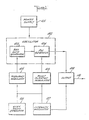
- Figure 1 shows a block diagrammatic version of an illustrative embodiment of the present invention.
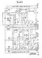
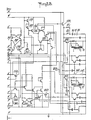
- FIGS. 2A and 2B when appropriately joined as shown, show a circuit schematic of a preferred embodiment of the present invention.
- FIG. 1 there is shown a block diagram of a transcutaneous nerve stimulation unit according to the present invention.
- a power supply 101 is understood suitably to deliver energizing voltages and current, as required, to the various other functional blocks of the unit.
- the power supply 101 is embodied as any of the numerous compact, long life dry cell batteries which are readily commercially available.
- An output stage 109 furnishes a stimulation pulse signal at output terminal 110, which conventionally is coupled to one or more electrodes deposited on the patient, as is known in the art. From the standpoint of the present invention, the more important parameters with respect to the output signal at 110 are its pulse duration, pulse frequency, and pulse amplitude.
- An oscillator 102 generates the basis of the stimulating signals, and couples them for suitable output amplification to the output stage 109.
- the oscillator 102 is divided into two parts, a repetition rate generator 103 and a pulse width generator 104.
- the repetition rate generation and pulse width generation may not be completely discrete as shown in functional blocks 103 and 104 of Figure 1, but from the standpoint of respective variation of each, they may be deemed functionally discrete as shown.
- the output signal from the oscillator 102 to the output stage 109, and in turn from the output terminal 110 to the patient involves a frequency range of 50 to 150 Hz, the width of each pulse varying between 20 and 150 psec.
- a scan ramp generator 108 (second oscillator) produces a signal, based upon which the control of output pulse duration, pulse frequency, and pulse amplitude is maintained.
- the scanning ramp generator 108 provides an output signal, advantageously defining successive increasing and decreasing ramps, the amplitude of which is the basis for respective frequency, pulse width, and pulse intensity modulation.
- the periodicity of the output signal from the scanning ramp generator 108 is substantially longer than the periodicity of the output from oscillator 102, preferably being at least an order of magnitude longer. In this fashion, the parameters of the output signal at 110 will be scanned through their respective ranges once for each half cycle of the signal from scanning ramp generator 108.
- the scanning ramp generator is coupled to the input terminals of a frequency modulator 105, a pulse duration modulator 106, and an intensity modulator 107.
- the frequency modulator 105 is coupled to repetition rate generator 103 of oscillator 102
- the pulse duration modulator 106 is coupled to the pulse width generator 104 of oscillator 102
- the intensity modulator 107 is coupled to the output stage 109.
- Each of the modulators 105, 106, and 107 provides a control signal, which in accordance with the knowledge of those of ordinary skill in the art may be an analog control voltage or a suitable digital word, responsive to which the associated parameter of the output signal is varied within its range.
- the frequency modulator 105 correspondingly provides a varying output control signal to the repetition rate generator 103 of oscillator 102, in turn producing a continuous frequency variation between range extremities for the output of oscillator 102, and in turn for the output signal at terminal 110.
- the pulse duration modulator 106 operates similarly in response to the ramp from generator 108, causing pulse width generator 104 of oscillator 102 to provide continuous variation in pulse width, from one range extremity to the other, and similarly so for the output signal at 110.
- the intensity modulator 107 controls the gain provided at the output stage 109, but it is understood that such modulation could also be accomplished directly at the output of oscillator 102. In any event, the pulse amplitude of the signal at 110 is thereby caused to be altered continuously between extremities of the selected pulse amplitude range.
- Figures 2A and 2B when joined at connections a-a' through s-s' respectively, show a detailed circuit schematic of a preferred embodiment of the present invention. It will be understood that the embodiment of Figures 2A and 2B defines a complete, operational transcutaneous electrical nerve stimulating unit, including not only the aspects set forth in block diagrammatic form in Figure 1, but also including other circuits and functional blocks suitable for incorporation in such a unit.
- FIG. 2B batteries B1, B2, and B3 are series connected, and when switches S1 and S2 are closed, power is provided to the various circuitry.
- the unit of Figures 2A and 2B is a dual output unit, having respective output stages at transformers T1 and T2, with the secondaries of each transformer being connectable to suitable leads, in turn conveying the output stimulating pulses to electrodes disposed at appropriate places on the patient's body.
- the embodiment of Figures 2A and 2B includes a voltage regulator function, with regulator transistor 229 having its emitter connected to the switches S1 and S2, and its base controlled by a differential amplifier formed by the emitter base junctions of transistors 226 and 224.
- the differential amplifier 226 and 224 senses the voltage attained by the difference between emitter-base voltage drops of transistors 221 and 222, off the regulated voltage, V cc , which is the voltage of the collector of regulating transistor 229 and the reference provided by the transistor 228.
- the voltage regulator function provides an independence of system parameters from battery voltage, as the batteries age and the battery voltages decrease.
- That oscillator which provides the essence of the output waveform in terms of pulse frequency and duration, is a free running, multivibrator type of circuit, wherein transistors 207, 208, and 209 are "on" when an output pulse is being produced, and are "off” during the interval between output pulses.
- Pulse duration is established by the operation of capacitor 404 in conjunction with resistors 338 and 372.
- Output pulse repetition frequency is controlled by the capacitor 403 in conjunction with resistors 336 and 337.
- the output pulse signal from the oscillator is coupled to the output stages, located at the rightmost portion of Figure 2B, via an alternating flip-flop including transistors 216 and 219, 217 and 218, and transistors 215 and 220.
- the flip-flop 216 and 219, in conjunction with steering transistors 217 and 218, provides an alternating pulse polarity.
- the scanning oscillator which fulfills the functions set forth with respect to scanning generator 108 of the Figure 1 embodiment, is located at the lower leftmost portion of Figure 2A.
- the scanning ramp generator is an oscillator which provides a substantially lower frequency than that of the output oscillator 102, the purpose of the scanning oscillator being to provide for parameter changes for scanning at a repetition frequency preferably measured in the range of seconds.
- the scanning oscillator includes transistors 235 and 236 connected in a monostable multivibrator configuration. Whenever transistor 235 is conducting, transistor 233 is also conducting to provide a current to transistors 232 and 237, with transistor 237 being a current source to capacitor 405.
- transistor 236 Conversely, if transistor 236 is conducting, transistor 238 acts as a current sink to the same capacitor, 405.
- Transistor 241 determines the inflection point in the positive direction
- transistor 242 determines the inflection point in the negative direction. Accordingly, the voltage on capacitor 405 alternately rises and falls during the alternate two phases of each cycle of transistors 235 and 236, respectively. This upward and downward voltage on capacitor 405 is translated into corresponding upward and downward currents from transistors 247 and 250.
- Transistor 247 modulates the charging current for capacitor 403, which in turn determines the repetition frequency of the basic oscillator.
- transistor 247 and its associated circuitry essentially fulfills the function attributed to the frequency modulator 105 of the Figure 1 embodiment.
- transistor 250 similarly modulates the pulse duration of the basic oscillator by modulating the charging current of capacitor 404. This corresponds to the operation of the pulse duration modulator 106 of Figure 1.
- Transistors 251 and 253 provide currents to the output circuits in Figure 2B, so that the amplitude of pulses from transistors 260 and 267 is similarly modulated.
- the emitter resistances in transistors 247, 250, 251, and 253 are selected so that the amount of scan or warbling is determined. That is, resistors 365, 366, 349, 340, 346, 347, and 356 afford an opportunity for adjustability of the various modulation parameters.
- Protection circuitry is provided at transistors 254, 255, 256, and 257 for sensing discontinuity at the output, such as might eventuate if the electrodes are detached from the patient.
- this aspect of the circuitry of Figures 2A and 2B provides an automatic disconnect function.
- Diode DS1 provides an indication to the user of the exercise of this feature.
Landscapes
- Health & Medical Sciences (AREA)
- Life Sciences & Earth Sciences (AREA)
- Biomedical Technology (AREA)
- Biophysics (AREA)
- Heart & Thoracic Surgery (AREA)
- Engineering & Computer Science (AREA)
- Pain & Pain Management (AREA)
- Nuclear Medicine, Radiotherapy & Molecular Imaging (AREA)
- Radiology & Medical Imaging (AREA)
- Animal Behavior & Ethology (AREA)
- General Health & Medical Sciences (AREA)
- Public Health (AREA)
- Veterinary Medicine (AREA)
- Electrotherapy Devices (AREA)
Claims (8)
Applications Claiming Priority (2)
| Application Number | Priority Date | Filing Date | Title |
|---|---|---|---|
| US05/945,974 US4210151A (en) | 1978-09-26 | 1978-09-26 | Electronic pain control with scanned output parameters |
| US945974 | 1978-09-26 |
Publications (3)
| Publication Number | Publication Date |
|---|---|
| EP0010364A2 EP0010364A2 (fr) | 1980-04-30 |
| EP0010364A3 EP0010364A3 (en) | 1980-07-23 |
| EP0010364B1 true EP0010364B1 (fr) | 1986-04-23 |
Family
ID=25483776
Family Applications (1)
| Application Number | Title | Priority Date | Filing Date |
|---|---|---|---|
| EP79301979A Expired EP0010364B1 (fr) | 1978-09-26 | 1979-09-24 | Neurostimulateur électrique transcutané |
Country Status (6)
| Country | Link |
|---|---|
| US (1) | US4210151A (fr) |
| EP (1) | EP0010364B1 (fr) |
| CA (1) | CA1118051A (fr) |
| DE (1) | DE2967593D1 (fr) |
| HK (1) | HK97686A (fr) |
| SG (1) | SG63586G (fr) |
Families Citing this family (41)
| Publication number | Priority date | Publication date | Assignee | Title |
|---|---|---|---|---|
| US4340063A (en) * | 1980-01-02 | 1982-07-20 | Empi, Inc. | Stimulation device |
| US4442839A (en) * | 1981-04-27 | 1984-04-17 | Empi, Inc. | Method of modulating energy in train of electrical pulses |
| US4431002A (en) * | 1981-06-08 | 1984-02-14 | Empi Inc. | Modulated deep afferent stimulator |
| US4453548A (en) * | 1981-06-08 | 1984-06-12 | Empi, Inc. | Method of improving sensory tolerance with modulated nerve stimulator |
| US4535777A (en) * | 1981-08-20 | 1985-08-20 | Physio Technology, Inc. | Method of providing electrical stimulation of tissue |
| NL8105297A (nl) * | 1981-11-23 | 1983-06-16 | Ver Wetens Onderwijs Gereform | Werkwijze voor het opwekken van zenuw- of spierstimulatiesignalen. |
| AU1573183A (en) * | 1982-06-18 | 1983-12-22 | Biostim Inc. | Biological electrical stimulators |
| CA1215128A (fr) * | 1982-12-08 | 1986-12-09 | Pedro Molina-Negro | Appareil de stimulation electrique des nerfs |
| DE3338361A1 (de) * | 1983-10-22 | 1985-05-09 | Moskovskij oblastnoj naučno-issledovatel'skij institut akušerstva i ginekologii, Moskau/Moskva | Einrichtung zur zentral-elektroanalgesie |
| IT8420627V0 (it) * | 1984-01-24 | 1984-01-24 | Tagliavini Antonio | Dispositivo elettronico portatile per la stimolazione corporea curativa. |
| DE3405630C1 (de) * | 1984-02-17 | 1985-06-27 | Wolfgang 2351 Trappenkamp Gräber | Gerät zur Schmerzbehandlung durch elektrische Stimulation |
| ES8703745A1 (es) * | 1984-06-05 | 1987-03-01 | Codman & Shurtleff | Un metodo para producir una secuencia o serie de pulsacionesde tratamiento en un dispositivo de estimulacion nerviosa transcutanea |
| US4664117A (en) * | 1984-10-09 | 1987-05-12 | Beck Stephen C | Apparatus and method for generating phosphenes |
| US4763656A (en) * | 1985-06-13 | 1988-08-16 | Beatrice T. Kester | Transcutaneous electrical nerve stimulation device and method |
| US4887603A (en) * | 1985-07-22 | 1989-12-19 | Empi, Inc. | Medical stimulator with stimulation signal characteristics modulated as a function of stimulation signal frequency |
| US4922908A (en) * | 1985-07-22 | 1990-05-08 | Empi, Inc. | Medical stimulator with stimulation signal characteristics modulated as a function of stimulation signal frequency |
| US4769881A (en) * | 1986-09-02 | 1988-09-13 | Pedigo Irby R | High precision tens apparatus and method of use |
| US4759368A (en) * | 1986-12-02 | 1988-07-26 | Medical Designs, Inc. | Transcutaneous nerve stimulator |
| EP0291577B1 (fr) * | 1987-05-20 | 1992-10-21 | PHYSIOMED-Medizintechnik GmbH | Dispositif de traitement de lymphostases et similaires |
| US4926865A (en) * | 1987-10-01 | 1990-05-22 | Oman Paul S | Microcomputer-based nerve and muscle stimulator |
| US4938223A (en) * | 1988-03-28 | 1990-07-03 | T. H. Charters, Inc. | Transcutaneous nerve block device |
| US4917092A (en) * | 1988-07-13 | 1990-04-17 | Medical Designs, Inc. | Transcutaneous nerve stimulator for treatment of sympathetic nerve dysfunction |
| US5184617A (en) * | 1990-06-05 | 1993-02-09 | Staodyn, Inc. | Output pulse compensation for therapeutic-type electronic devices |
| US5205284A (en) * | 1990-06-12 | 1993-04-27 | Zoll Medical Corporation | Method and apparatus for transcutaneous electrical cardiac pacing with background stimulation |
| US5193537A (en) * | 1990-06-12 | 1993-03-16 | Zmd Corporation | Method and apparatus for transcutaneous electrical cardiac pacing |
| EP0532143A1 (fr) * | 1991-09-12 | 1993-03-17 | BIOTRONIK Mess- und Therapiegeräte GmbH & Co Ingenieurbüro Berlin | Neurostimulateur |
| US5350414A (en) * | 1991-12-10 | 1994-09-27 | Electro Science Technologies, Inc. | Local application microprocessor based nerve and muscle stimulator |
| US5487759A (en) * | 1993-06-14 | 1996-01-30 | Bastyr; Charles A. | Nerve stimulating device and associated support device |
| US5983141A (en) | 1996-06-27 | 1999-11-09 | Radionics, Inc. | Method and apparatus for altering neural tissue function |
| US5690688A (en) * | 1996-11-12 | 1997-11-25 | Pacesetter Ab | Medical therapy apparatus which administers therapy adjusted to follow natural variability of the physiological function being controlled |
| USRE40279E1 (en) | 1997-06-26 | 2008-04-29 | Sherwood Services Ag | Method and system for neural tissue modification |
| US6512955B1 (en) | 2000-08-07 | 2003-01-28 | Mcenany Thomas J. | Electrical apparatus for therapeutic treatment |
| US7050856B2 (en) | 2002-01-11 | 2006-05-23 | Medtronic, Inc. | Variation of neural-stimulation parameters |
| US8355789B2 (en) * | 2006-04-28 | 2013-01-15 | Medtronic, Inc. | Method and apparatus providing asynchronous neural stimulation |
| US8498710B2 (en) | 2009-07-28 | 2013-07-30 | Nevro Corporation | Linked area parameter adjustment for spinal cord stimulation and associated systems and methods |
| US9895538B1 (en) | 2013-01-22 | 2018-02-20 | Nevro Corp. | Systems and methods for deploying patient therapy devices |
| US9731133B1 (en) | 2013-01-22 | 2017-08-15 | Nevro Corp. | Systems and methods for systematically testing a plurality of therapy programs in patient therapy devices |
| US9295840B1 (en) | 2013-01-22 | 2016-03-29 | Nevro Corporation | Systems and methods for automatically programming patient therapy devices |
| US9662269B2 (en) * | 2013-10-22 | 2017-05-30 | Innovative Health Solutions, Inc. | Systems and methods for auricular peripheral nerve field stimulation |
| US9517344B1 (en) | 2015-03-13 | 2016-12-13 | Nevro Corporation | Systems and methods for selecting low-power, effective signal delivery parameters for an implanted pulse generator |
| US10300277B1 (en) | 2015-12-14 | 2019-05-28 | Nevro Corp. | Variable amplitude signals for neurological therapy, and associated systems and methods |
Citations (1)
| Publication number | Priority date | Publication date | Assignee | Title |
|---|---|---|---|---|
| GB1488957A (en) * | 1974-03-01 | 1977-10-19 | Stimulation Tech Inc | Apparatus for electric pulse stimulation |
Family Cites Families (8)
| Publication number | Priority date | Publication date | Assignee | Title |
|---|---|---|---|---|
| US2099511A (en) * | 1933-03-16 | 1937-11-16 | Caesar Viktor | Oscillator for the biological treatment of living tissue |
| BE441810A (fr) * | 1940-06-21 | |||
| US2381496A (en) * | 1942-10-10 | 1945-08-07 | Rca Corp | Method of generating currents for nonsignaling purposes |
| DE970276C (de) * | 1951-11-29 | 1958-09-04 | Hermann Staehle Fa Dipl Ing | Elektromedizinisches Behandlungsgeraet zur Schmerzbekaempfung durch periodisch variierende Stroeme |
| US3299892A (en) * | 1963-07-15 | 1967-01-24 | Dynapower Systems Corp | Therapeutic pulse generation, control and transmission circuit |
| FR2147792B1 (fr) * | 1971-07-07 | 1975-06-06 | Guerineau Jacques | |
| DE2158132C2 (de) * | 1971-11-24 | 1974-01-03 | Robert Bosch Elektronik Gmbh, 1000 Berlin Und 7000 Stuttgart | Reizstrom-Diagnostikgerät |
| CH577323A5 (en) * | 1973-07-23 | 1976-07-15 | Frefel Sa | Electric physiotherapy apparatus - uses direct and alternating current simultaneously in surges over predetermined frequency range and is supplied via transformer |
-
1978
- 1978-09-26 US US05/945,974 patent/US4210151A/en not_active Expired - Lifetime
-
1979
- 1979-09-24 DE DE7979301979T patent/DE2967593D1/de not_active Expired
- 1979-09-24 EP EP79301979A patent/EP0010364B1/fr not_active Expired
- 1979-09-24 CA CA000336200A patent/CA1118051A/fr not_active Expired
-
1986
- 1986-07-21 SG SG63586A patent/SG63586G/en unknown
- 1986-12-11 HK HK976/86A patent/HK97686A/xx unknown
Patent Citations (1)
| Publication number | Priority date | Publication date | Assignee | Title |
|---|---|---|---|---|
| GB1488957A (en) * | 1974-03-01 | 1977-10-19 | Stimulation Tech Inc | Apparatus for electric pulse stimulation |
Also Published As
| Publication number | Publication date |
|---|---|
| HK97686A (en) | 1986-12-19 |
| US4210151A (en) | 1980-07-01 |
| DE2967593D1 (en) | 1986-05-28 |
| EP0010364A2 (fr) | 1980-04-30 |
| EP0010364A3 (en) | 1980-07-23 |
| SG63586G (en) | 1987-03-27 |
| CA1118051A (fr) | 1982-02-09 |
Similar Documents
| Publication | Publication Date | Title |
|---|---|---|
| EP0010364B1 (fr) | Neurostimulateur électrique transcutané | |
| EP0009920B1 (fr) | Stimulateur électronique de tissus avec des signaux de sortie commandés | |
| US5324317A (en) | Interferential stimulator for applying low frequency alternating current to the body | |
| US4535777A (en) | Method of providing electrical stimulation of tissue | |
| US4431002A (en) | Modulated deep afferent stimulator | |
| US5133351A (en) | Low-frequency electrotherapeutic device | |
| CA2317232C (fr) | Stimulateur corporel electrique | |
| EP0111229B1 (fr) | Dispositif pour la stimulation électrique des nerfs | |
| US5913882A (en) | Neural stimulation techniques with feedback | |
| US4233986A (en) | Apparatus and method for controlling pain by transcutaneous electrical stimulation (TES) | |
| US4690142A (en) | Method and system for utilizing electro-neuro stimulation in a bio-feedback system | |
| US4233965A (en) | Method and apparatus for the therapeutic treatment of living tissue | |
| US2622601A (en) | Electric nerve stimulator | |
| US5447526A (en) | Transcutaneous electric muscle/nerve controller/feedback unit | |
| US3941137A (en) | Ambulatory stimulator | |
| US5443441A (en) | Apparatus and method for transdermal delivery of cosmetic compositions | |
| US3344792A (en) | Method of muscular stimulation in human beings to aid in walking | |
| US4754759A (en) | Neural conduction accelerator and method of application | |
| US4222386A (en) | Method for stimulating cardiac action by means of implanted _electrocardiostimulator and implantable electrocardiostimulator for effecting same | |
| US4453548A (en) | Method of improving sensory tolerance with modulated nerve stimulator | |
| JPH03505051A (ja) | 生体刺激用の電気パルスを発生させる方法およびその装置 | |
| JP6837504B2 (ja) | 電気治療装置 | |
| EP2106274A2 (fr) | Dispositif d'électrostimulation pour faire circuler le sang dans les jambes | |
| US4442839A (en) | Method of modulating energy in train of electrical pulses | |
| ATE329651T1 (de) | Elektrisches stimulationssystem zur behandlung von phantomglierderschmerzen |
Legal Events
| Date | Code | Title | Description |
|---|---|---|---|
| PUAI | Public reference made under article 153(3) epc to a published international application that has entered the european phase |
Free format text: ORIGINAL CODE: 0009012 |
|
| AK | Designated contracting states |
Designated state(s): BE CH DE FR GB IT NL SE |
|
| PUAL | Search report despatched |
Free format text: ORIGINAL CODE: 0009013 |
|
| AK | Designated contracting states |
Designated state(s): BE CH DE FR GB IT NL SE |
|
| 17P | Request for examination filed |
Effective date: 19810108 |
|
| RAP1 | Party data changed (applicant data changed or rights of an application transferred) |
Owner name: CODMAN & SHURTLEFF INC. |
|
| GRAA | (expected) grant |
Free format text: ORIGINAL CODE: 0009210 |
|
| AK | Designated contracting states |
Kind code of ref document: B1 Designated state(s): BE CH DE FR GB IT NL SE |
|
| REF | Corresponds to: |
Ref document number: 2967593 Country of ref document: DE Date of ref document: 19860528 |
|
| ET | Fr: translation filed | ||
| ITF | It: translation for a ep patent filed | ||
| PLBE | No opposition filed within time limit |
Free format text: ORIGINAL CODE: 0009261 |
|
| STAA | Information on the status of an ep patent application or granted ep patent |
Free format text: STATUS: NO OPPOSITION FILED WITHIN TIME LIMIT |
|
| 26N | No opposition filed | ||
| PGFP | Annual fee paid to national office [announced via postgrant information from national office to epo] |
Ref country code: NL Payment date: 19870930 Year of fee payment: 9 |
|
| PG25 | Lapsed in a contracting state [announced via postgrant information from national office to epo] |
Ref country code: CH Effective date: 19880930 Ref country code: BE Effective date: 19880930 |
|
| BERE | Be: lapsed |
Owner name: CODMAN & SHURTLEFF INC. Effective date: 19880930 |
|
| PG25 | Lapsed in a contracting state [announced via postgrant information from national office to epo] |
Ref country code: NL Effective date: 19890401 |
|
| NLV4 | Nl: lapsed or anulled due to non-payment of the annual fee | ||
| REG | Reference to a national code |
Ref country code: CH Ref legal event code: PL |
|
| PGFP | Annual fee paid to national office [announced via postgrant information from national office to epo] |
Ref country code: FR Payment date: 19890926 Year of fee payment: 11 |
|
| PGFP | Annual fee paid to national office [announced via postgrant information from national office to epo] |
Ref country code: SE Payment date: 19890927 Year of fee payment: 11 |
|
| PGFP | Annual fee paid to national office [announced via postgrant information from national office to epo] |
Ref country code: GB Payment date: 19890930 Year of fee payment: 11 |
|
| PGFP | Annual fee paid to national office [announced via postgrant information from national office to epo] |
Ref country code: DE Payment date: 19891031 Year of fee payment: 11 |
|
| PG25 | Lapsed in a contracting state [announced via postgrant information from national office to epo] |
Ref country code: GB Effective date: 19900924 |
|
| PG25 | Lapsed in a contracting state [announced via postgrant information from national office to epo] |
Ref country code: SE Effective date: 19900925 |
|
| GBPC | Gb: european patent ceased through non-payment of renewal fee | ||
| PG25 | Lapsed in a contracting state [announced via postgrant information from national office to epo] |
Ref country code: FR Effective date: 19910530 |
|
| PG25 | Lapsed in a contracting state [announced via postgrant information from national office to epo] |
Ref country code: DE Effective date: 19910601 |
|
| REG | Reference to a national code |
Ref country code: FR Ref legal event code: ST |
|
| EUG | Se: european patent has lapsed |
Ref document number: 79301979.5 Effective date: 19910527 |