EP0010453B1 - Structure tridimensionelle repliable - Google Patents
Structure tridimensionelle repliable Download PDFInfo
- Publication number
- EP0010453B1 EP0010453B1 EP79302322A EP79302322A EP0010453B1 EP 0010453 B1 EP0010453 B1 EP 0010453B1 EP 79302322 A EP79302322 A EP 79302322A EP 79302322 A EP79302322 A EP 79302322A EP 0010453 B1 EP0010453 B1 EP 0010453B1
- Authority
- EP
- European Patent Office
- Prior art keywords
- support arms
- elongate members
- axes
- support
- cross
- Prior art date
- Legal status (The legal status is an assumption and is not a legal conclusion. Google has not performed a legal analysis and makes no representation as to the accuracy of the status listed.)
- Expired
Links
Images

Classifications
-
- A—HUMAN NECESSITIES
- A47—FURNITURE; DOMESTIC ARTICLES OR APPLIANCES; COFFEE MILLS; SPICE MILLS; SUCTION CLEANERS IN GENERAL
- A47C—CHAIRS; SOFAS; BEDS
- A47C19/00—Bedsteads
- A47C19/12—Folding bedsteads
- A47C19/126—Folding bedsteads foldable side to side and head to foot, e.g. umbrella type
-
- A—HUMAN NECESSITIES
- A47—FURNITURE; DOMESTIC ARTICLES OR APPLIANCES; COFFEE MILLS; SPICE MILLS; SUCTION CLEANERS IN GENERAL
- A47D—FURNITURE SPECIALLY ADAPTED FOR CHILDREN
- A47D7/00—Children's beds
- A47D7/002—Children's beds foldable
Definitions
- the present invention relates to a collapsible three-dimensional structure and more particularly to a collapsible bed or cot incorporating such a structure.
- US-A-2 974 325 discloses a convertible bed in which a rectangular basket member is supported by four interconnected X-frames which together form a three-dimensional collapsible structure comprising first and second elongate members which each have first and second ends and are pivotally interconnected to form a first of said X-frames; support means, including a second of said X-frames which is spaced from said first X-frame, for limiting separation of the first ends of the first and second elongate members; and first and second cross-braces, respectively forming parts of the X-frames interconnecting said first and second X-frames, respectively provided with first ends pivotally connected at or adjacent the second ends of the second and first elongate members, respectively, and respectively provided with second ends pivotally connected to the second X-frame and, thus, to the ⁇ support means.
- X-frames are all the same size
- this object is achieved by providing the structure with first and second sleeves respectively connected to the first ends of the first and second elongate members for pivotal movement about axes which extend perpendicular to the pivotal axis between the first and second elongate members and perpendicular, respectively, to the first and second elongate members; first and second support arms respectively slidable within the first and second sleeves and each having first and second ends; and first and second stops respectively provided at the first ends of the first and second support arms; and by pivotally connecting the second ends of the first and second support arms, to the support means.
- the stops on the first ends of the support arms limit movement of the sleeves, and hence the first X-frame, away from the support means when the structure is in its extended condition.
- the structure can be collapsed by sliding the sleeves along the support arm until the first ends of the elongate members are adjacent the second ends of the support arms.
- the cross-braces pivot relative to the support arms and so cause the first and second elongate members of the X-frame to rotate relative to each other so that the first ends of these elongate members, and hence also the second ends, come together.
- the elongate members, support arms and cross-braces all extend substantially parallel to each other to form a compact bundle. The compactness of this bundle is determined by the dimensions of the components and can be easily adjusted to obtain acceptable results.
- the support means include third and fourth elongate members which each have first and second ends and are pivotally interconnected to form a second X-frame.
- the first ends of the third and fourth elongate members may be pivotally connected to the second ends of the support arms and the separation of the second ends of the support arms may be more effectively limited by providing tie means between the second ends of the third and fourth elongate members of the second X-frame.
- a first bracket may provide pivotal connections for the second end of the first support arm and for the second end of the first cross-brace so that these second ends are respectively pivotable about two spaced parallel axes; and a second bracket may provide pivotal connections for the second end of the second support arm and for the second end of the second cross-brace so that these second ends are respectively pivotable about two spaced parallel axes.
- This separation of axes facilitates movement of the sleeves along the support arms towards the second ends of the support arms.
- the support means constitute a sub-assembly which is identical to the remainder of the structure.
- third and fourth sleeves are respectively connected to the first ends of the third and fourth elongate members for pivotal movement about axes which extend perpendicular to the pivotal axis between the third and fourth elongate members and perpendicular, respectively, to the third and fourth elongate members;
- third and fourth support arms are respectively slidable within the third and fourth sleeves and each have first and second ends;
- third and fourth stops are respectively provided at the first ends of the third and fourth support arms;
- third and fourth cross-braces are respectively provided with first ends pivotally connected at or adjacent the second ends of the fourth and third elongate members, respectively, and respectively provided with second ends pivotally connected to the second ends of the third and fourth support arms, respectively.
- the second ends of the first and third support arms are interconnected and are each pivotable about an axis which extends perpendicular to a plane defined by the axes of the first and third support arms and the axes of the first and third cross-braces; and the second ends of the second and fourth support . arms are interconnected and are each pivotable about an axis which extends perpendicular to a plane defined by the axes of the second and fourth support arms and the axes of the second and fourth cross-braces.
- the second ends of the first and second support arms support the second ends of a third and fourth support arms so as to limit separation of the second ends of the third and fourth support arms.
- the second ends of the third and fourth support arms limit separation of the second ends of the first and second support arms.
- a first interconnecting bracket provides pivotal connections for the second ends of the first and third support arms which seond ends are respectively pivotable about spaced axes extending perpendicular to a plane defined by the axes of the first and third support arms and of the first and third cross-braces; and a second interconnecting bracket provides pivotal connections for the second ends of the second and fourth support arms which second ends are respectively pivotable about two spaced axes extending perpendicular to a plane defined by the axes of the second and fourth support arms and of the second and fourth cross-braces.
- this separation of pivotal axes facilitates movement of the sleeves along the support arms towards the second ends of the support arms.
- Locking means for holding structures according to the invention in an extended condition, include stiffening strips extending between the first and second ends of each support arm so as to maintain the sleeve which slidably receives said support arm in abutment with the stop provided at the first end of said support arm.
- the stiffening strips may be attached to this rim of the container.
- a container such as this is preferably a rectangular parallelepiped having rectilinear edges and so stiffening members may be provided for reinforcing at least some of these edges so as to impart additional rigidity to the structure.
- stiffening members may be provided for reinforcing at least some of these edges so as to impart additional rigidity to the structure.
- at least some of these edges may be detachably connected to the cross-braces of the structure.
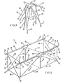
- the collapsible structure 1 shown in Figure 1 comprises a first X-frame 10 having first and second elongate members 4 and 5 which are pivotally interconnected and a second X-frame 33 having third and fourth elongate members 27 and 28.
- First and second support arms 13 and 14 and first and second cross-braces 21 and 22 interconnect the two X-frames 10 and 33.
- First and second sleeves 11 and 12 are pivotally connected to the first ends 6 and 8 of the first and second elongate members 4 and 5 of the first X-frame 10 and slidably receive the first and second support arms-1 3 and 14. Stops 19 and 20 provided on the first ends 15 and 17 of the support arms 13 and 14 limit movement of the support arms 13 and 14 relative to the first X-frame 10 and the second ends 16 and 18 of the support arms 13 and 14 are pivotally connected to brackets 34 and 35.
- the first ends 23 and 24 of the two cross-braces 21 and 22 are pivotally connected to the second and first elongate members 5 and 4, respectively, adjacent the second ends 9 and 7 of these members and the second ends 25 and 26 of the first and second cross-braces 21 and 22 are also pivoted to the brackets 34 and 35.
- the first ends 29 and 31 of the third and fourth elongate members 27 and 28 are also pivotally connected to the brackets 34 and 35.
- the second X-frame 33 therefore serves as support means for limiting separation of the second ends 16 and 18 of the first and second support arms 13 and 14. This may be achieved by connecting tie means (not shown) between the second ends 30 and 32 of the third and fourth elongate members 27 and 28. Rubber feet 60 are attached to the elongate members forming the two X-frames so that the collapsible structure can be stood upon a support surface.
- the first X-frame 10 is moved towards the second X-frame 33.
- This causes the first and second cross-braces 21 and 22 to swing away from the first and second support arms 13 and 14.
- the second ends 9 and 7 of the second and first elongate members 5 and 4 are respectively moved away from the first ends 6 and 8 of the first and second elongate members 4 and 5.
- the first ends 6 and 8 of the first and second elongate members 4 and 5 pivot about the sleeves 11 and 12 and so align themselves substantially parallel with the support arms 13 and 14 and with the cross-braces 21 and 22.
- the third and fourth. elongate members 27 and 28 of the second X-frame 33 collapse in a similar manner to the elongate members 4 and 5 of the first X-frame 10 and so, as all of the elongate members depend from the brackets 34 and 35, these brackets 34 and 35 are conveniently formed as carrying handles.
- brackets 34 and 35 of the embodiment illustrated in Figure 1 are replaced by brackets 52 and 53 and the second X-frame 33 is connected to these brackets 52 and 53 in the same manner as the first X-frame 10.
- third and fourth sleeves 36 and 37 are pivotally connected to the first ends 29 and 31 of the third and fourth elongate members 27 and 28;
- third and fourth support arms 38 and 39 are slidably received in these sleeves 36 and 37 and have first and second stops 44 and 45 at their first ends 40 and 42 and are pivotably connected to the brackets 52 and 53 at their second ends 41 and 43;
- third and fourth cross-braces 46 and 47 have first ends 48 and 49 respectively pivoted to the fourth and third elongate members 28 and 27, adjacent the second ends 32 and 30 of these elongate members 28 and 37 and second ends 50 and 51 respectively pivoted to the brackets 52 and 53.
- both X-frames collapse in a similar manner to the collapse of the first X-frame 10, as described with reference to Figure 1.
- the first ends 6 and 8 of the first and second elongate members 4 and 5 move together and the first ends 29 and 31 of the third and fourth elongate members 27 and 28 move together;
- the first and second cross-braces 21 and 22 swing away from the first and second support arms 13 and 14 and the third and fourth cross-braces 46 and 47 swing away from the third and fourth support arms 38 and 39;
- the first and second sleeves 11 and 12 pivot about the first ends 6 and 8 of the first and second elongate members 4 and 5 and the third and fourth sleeves 36 and 37 pivot about the first ends 29 and 31 of the third and fourth elongate members 27 and 28 and so the support arms 13, 14, 38 and 39 swing towards their adjacent cross-braces 21, 22, 46 and 47 so
- the collapsible structure 3 includes, in addition to the components shown in Figure 2, a container 55 of pliable material, such as cloth or canvas, in the form of an open-topped parallelepiped. Hems (not shown) formed in side portions of the rim 56 of this container 55 receive the support arms 13, 14, 38 and 39.
- stiffening strips 54 extend between the sleeves 11 and 36, on one side of the structure 3, and between the sleeves 12 and 37, on the otherside of the structure 3.
- stiffening strips 54 are detachably connected -to the hems (not shown) which receive the support arms 13, 14, 38 and 39 and may extend from each corner of the structure 3 over the whole length of the side of the structure 3 or may extend from the corners to the brackets 52 and 53 at the mid-points of these sides.
- Stiffening members 57 and 58 are detachably provided around the bottom edges of the container 55 and vertical stiffening members 59 are detachably provided at the corner edges of the container 55. Further reinforcing strips 61 extend around the central portion of the container 55. Finally, to provide still further rigidity, the four bottom corners of the container 55 are provided with snap-action clips (not shown) for detachable connection to the cross-braces 21, 22, 46 and 47 and, in normal use, a relatively stiff mattress (not shown) is installed in the bottom of the container 55.
- the mattress When it is necessary to collapse the structure 3, the mattress is removed, the bottom corners of the container 55 are disconnected from the cross-braces 21, 22, 46 and 47 and the stiffening strips 54, stiffening members 57, 58 and 59, and the reinforcing strips 61 are all removed.
- the X-frames 10 and 33 are then moved towards each other, as described with reference to Figures 2 and 3.
- the hems which receive the support arms 13, 14, 38 and 39 are "gathered up” and shortened in length so as to be accommodated between the sleeves 11, 12, 36 and 37 and the remainder of the container 55 is compressed, in crumpled condition, internally of the members which become aligned substantial parallel with each other.
Landscapes
- Fats And Perfumes (AREA)
- Acyclic And Carbocyclic Compounds In Medicinal Compositions (AREA)
- Prostheses (AREA)
- Invalid Beds And Related Equipment (AREA)
- Packaging Of Annular Or Rod-Shaped Articles, Wearing Apparel, Cassettes, Or The Like (AREA)
- Toys (AREA)
- Auxiliary Devices For And Details Of Packaging Control (AREA)
- Orthopedics, Nursing, And Contraception (AREA)
Claims (10)
Priority Applications (1)
| Application Number | Priority Date | Filing Date | Title |
|---|---|---|---|
| AT79302322T ATE2995T1 (de) | 1978-10-24 | 1979-10-24 | Zusammen-klappbare drei-dimensionale struktur. |
Applications Claiming Priority (2)
| Application Number | Priority Date | Filing Date | Title |
|---|---|---|---|
| GB7841760 | 1978-10-24 | ||
| GB4176078 | 1978-10-24 |
Publications (2)
| Publication Number | Publication Date |
|---|---|
| EP0010453A1 EP0010453A1 (fr) | 1980-04-30 |
| EP0010453B1 true EP0010453B1 (fr) | 1983-04-13 |
Family
ID=10500551
Family Applications (1)
| Application Number | Title | Priority Date | Filing Date |
|---|---|---|---|
| EP79302322A Expired EP0010453B1 (fr) | 1978-10-24 | 1979-10-24 | Structure tridimensionelle repliable |
Country Status (6)
| Country | Link |
|---|---|
| US (1) | US4304017A (fr) |
| EP (1) | EP0010453B1 (fr) |
| JP (1) | JPS5599216A (fr) |
| AT (1) | ATE2995T1 (fr) |
| AU (1) | AU527651B2 (fr) |
| DE (1) | DE2965216D1 (fr) |
Families Citing this family (13)
| Publication number | Priority date | Publication date | Assignee | Title |
|---|---|---|---|---|
| GB2092626B (en) * | 1981-05-05 | 1984-08-30 | Todo Seisakusho Ltd | A full automatic leasing machine for a warp beam containing warps of different colours |
| JPS58175511A (ja) * | 1982-04-09 | 1983-10-14 | アップリカ葛西株式会社 | ベビ−ベツド |
| US4819285A (en) * | 1986-07-11 | 1989-04-11 | Indwell Products Corporation | Portable collapsible baby crib |
| US5363521A (en) * | 1992-06-01 | 1994-11-15 | Fisher-Price, Inc. | Collapsible playpen |
| FR2753159B1 (fr) | 1996-09-10 | 1999-03-26 | Ampafrance | Dispositif d'accrochage d'une nacelle sur une poussette pour enfant, poussette et support equipes d'un tel dispositif |
| FR2769815B1 (fr) * | 1997-10-21 | 2000-01-07 | Ampafrance | Lit pliant, notamment pour enfant, a pliage rapide |
| US8024825B2 (en) * | 2000-08-22 | 2011-09-27 | Richard Harrison | Collapsible crib |
| US7036161B2 (en) | 2000-08-22 | 2006-05-02 | Harrison Richard J | Collapsible structures |
| CN200941953Y (zh) * | 2006-08-10 | 2007-09-05 | 明门实业股份有限公司 | 可收折婴儿床架 |
| CN201119618Y (zh) * | 2007-02-15 | 2008-09-24 | 厦门进雄企业有限公司 | 一种折叠支撑架及交叉架 |
| US7845030B1 (en) | 2007-04-10 | 2010-12-07 | Pollard Ronald L | Collapsible platform for a mattress |
| US10448752B1 (en) | 2015-04-09 | 2019-10-22 | Regalo International, Llc | Playyard |
| US10194755B1 (en) | 2015-04-09 | 2019-02-05 | Regalo International, Llc | Playyard |
Citations (1)
| Publication number | Priority date | Publication date | Assignee | Title |
|---|---|---|---|---|
| US2974325A (en) * | 1958-03-10 | 1961-03-14 | Mango Roberto | Convertible bed |
Family Cites Families (6)
| Publication number | Priority date | Publication date | Assignee | Title |
|---|---|---|---|---|
| GB191512074A (en) * | 1915-08-21 | 1916-08-21 | Alfred Thomas Scorey | Improvements in Hand Propelled Folding Carriages or Wheeling Chairs. |
| US1330901A (en) * | 1919-03-26 | 1920-02-17 | John W Richards | Collapsible spring cot-bed |
| FR1040887A (fr) * | 1951-07-20 | 1953-10-19 | Bebe X Ets | Support pliant, notamment pour berceau et baignoire d'enfant |
| US3206772A (en) * | 1963-10-31 | 1965-09-21 | Thayer Inc | Folding playpen |
| US4202065A (en) * | 1977-05-23 | 1980-05-13 | Sullivan Barry J | Collapsible baby enclosure |
| JP2563261Y2 (ja) * | 1992-06-19 | 1998-02-18 | ローム株式会社 | Dip型電子部品におけるリード端子の曲がり検出装置 |
-
1979
- 1979-10-23 AU AU52049/79A patent/AU527651B2/en not_active Ceased
- 1979-10-23 US US06/087,635 patent/US4304017A/en not_active Expired - Lifetime
- 1979-10-24 JP JP13750479A patent/JPS5599216A/ja active Pending
- 1979-10-24 EP EP79302322A patent/EP0010453B1/fr not_active Expired
- 1979-10-24 AT AT79302322T patent/ATE2995T1/de not_active IP Right Cessation
- 1979-10-24 DE DE7979302322T patent/DE2965216D1/de not_active Expired
Patent Citations (1)
| Publication number | Priority date | Publication date | Assignee | Title |
|---|---|---|---|---|
| US2974325A (en) * | 1958-03-10 | 1961-03-14 | Mango Roberto | Convertible bed |
Also Published As
| Publication number | Publication date |
|---|---|
| ATE2995T1 (de) | 1983-04-15 |
| US4304017A (en) | 1981-12-08 |
| AU527651B2 (en) | 1983-03-17 |
| DE2965216D1 (en) | 1983-05-19 |
| EP0010453A1 (fr) | 1980-04-30 |
| AU5204979A (en) | 1980-05-01 |
| JPS5599216A (en) | 1980-07-29 |
Similar Documents
| Publication | Publication Date | Title |
|---|---|---|
| US4304017A (en) | Collapsible structure particularly for use as a cot or bed | |
| EP0007955B1 (fr) | Cadre pliant de poussette d'enfant | |
| CA1062307A (fr) | Poussette pliante | |
| EP0000437B2 (fr) | Châssis de chaise pliante | |
| EP0142340B1 (fr) | Chaise pliante avec accoudoir | |
| US3390893A (en) | Structures for folding baby-carriages, chairs, and the like | |
| US6035466A (en) | Collapsible baby bed | |
| US4948077A (en) | Laundry buggy | |
| US2617999A (en) | Folding bed | |
| US3018493A (en) | Baby bed play pen | |
| US4077640A (en) | Perambulator foldable support frame | |
| US5711040A (en) | Folding collapsible frame structure for a baby's crib | |
| CA1050407A (fr) | Fauteuil roulant a large siege | |
| US3206772A (en) | Folding playpen | |
| EP0104884A2 (fr) | Cadre de chaise pliante | |
| US4229845A (en) | Collapsible hammock support | |
| US5025517A (en) | Collapsible structure suitable for use as a portable play yard | |
| GB2099765A (en) | Push chair | |
| US2390660A (en) | Folding reclining bedboard | |
| GB2331233A (en) | A collapsible combined sun-bed and deck-chair | |
| US3187352A (en) | Play pen | |
| GB2177354A (en) | Shopping trolleys | |
| GB2110645A (en) | A collapsible tank for liquids | |
| GB1584110A (en) | Folding push-chairs | |
| GB2113625A (en) | Collapsible trolley |
Legal Events
| Date | Code | Title | Description |
|---|---|---|---|
| PUAI | Public reference made under article 153(3) epc to a published international application that has entered the european phase |
Free format text: ORIGINAL CODE: 0009012 |
|
| AK | Designated contracting states |
Kind code of ref document: A1 Designated state(s): AT BE CH DE FR GB IT LU NL SE |
|
| 17P | Request for examination filed |
Effective date: 19801021 |
|
| ITF | It: translation for a ep patent filed | ||
| GRAA | (expected) grant |
Free format text: ORIGINAL CODE: 0009210 |
|
| AK | Designated contracting states |
Kind code of ref document: B1 Designated state(s): AT BE CH DE FR GB IT LU NL SE |
|
| REF | Corresponds to: |
Ref document number: 2995 Country of ref document: AT Date of ref document: 19830415 Kind code of ref document: T |
|
| REF | Corresponds to: |
Ref document number: 2965216 Country of ref document: DE Date of ref document: 19830519 |
|
| ET | Fr: translation filed | ||
| PGFP | Annual fee paid to national office [announced via postgrant information from national office to epo] |
Ref country code: SE Payment date: 19830930 Year of fee payment: 5 |
|
| PGFP | Annual fee paid to national office [announced via postgrant information from national office to epo] |
Ref country code: AT Payment date: 19831012 Year of fee payment: 5 |
|
| PGFP | Annual fee paid to national office [announced via postgrant information from national office to epo] |
Ref country code: FR Payment date: 19831014 Year of fee payment: 5 |
|
| PGFP | Annual fee paid to national office [announced via postgrant information from national office to epo] |
Ref country code: LU Payment date: 19831017 Year of fee payment: 5 |
|
| PGFP | Annual fee paid to national office [announced via postgrant information from national office to epo] |
Ref country code: NL Payment date: 19831027 Year of fee payment: 5 |
|
| PG25 | Lapsed in a contracting state [announced via postgrant information from national office to epo] |
Ref country code: LU Free format text: LAPSE BECAUSE OF NON-PAYMENT OF DUE FEES Effective date: 19831031 |
|
| PGFP | Annual fee paid to national office [announced via postgrant information from national office to epo] |
Ref country code: CH Payment date: 19831109 Year of fee payment: 5 |
|
| PGFP | Annual fee paid to national office [announced via postgrant information from national office to epo] |
Ref country code: DE Payment date: 19831125 Year of fee payment: 5 |
|
| PGFP | Annual fee paid to national office [announced via postgrant information from national office to epo] |
Ref country code: BE Payment date: 19831130 Year of fee payment: 5 |
|
| PG25 | Lapsed in a contracting state [announced via postgrant information from national office to epo] |
Ref country code: AT Effective date: 19841024 |
|
| PG25 | Lapsed in a contracting state [announced via postgrant information from national office to epo] |
Ref country code: SE Effective date: 19841025 |
|
| PG25 | Lapsed in a contracting state [announced via postgrant information from national office to epo] |
Ref country code: CH Effective date: 19841031 Ref country code: BE Effective date: 19841031 |
|
| BERE | Be: lapsed |
Owner name: ANDREWS MACLAREN LTD Effective date: 19841024 |
|
| PG25 | Lapsed in a contracting state [announced via postgrant information from national office to epo] |
Ref country code: NL Effective date: 19850501 |
|
| GBPC | Gb: european patent ceased through non-payment of renewal fee | ||
| NLV4 | Nl: lapsed or anulled due to non-payment of the annual fee | ||
| PG25 | Lapsed in a contracting state [announced via postgrant information from national office to epo] |
Ref country code: FR Free format text: LAPSE BECAUSE OF NON-PAYMENT OF DUE FEES Effective date: 19850628 |
|
| REG | Reference to a national code |
Ref country code: CH Ref legal event code: PL |
|
| PG25 | Lapsed in a contracting state [announced via postgrant information from national office to epo] |
Ref country code: DE Effective date: 19850702 |
|
| REG | Reference to a national code |
Ref country code: FR Ref legal event code: ST |
|
| PG25 | Lapsed in a contracting state [announced via postgrant information from national office to epo] |
Ref country code: GB Effective date: 19881118 |
|
| EUG | Se: european patent has lapsed |
Ref document number: 79302322.7 Effective date: 19851007 |
|
| PLBE | No opposition filed within time limit |
Free format text: ORIGINAL CODE: 0009261 |
|
| STAA | Information on the status of an ep patent application or granted ep patent |
Free format text: STATUS: NO OPPOSITION FILED WITHIN TIME LIMIT |