EP0010505A1 - Stecker für optische Fasern und Vorrichtung zum Einbau der Fasern in Zwingen, die direkt im Stecker benutzt werden - Google Patents
Stecker für optische Fasern und Vorrichtung zum Einbau der Fasern in Zwingen, die direkt im Stecker benutzt werden Download PDFInfo
- Publication number
- EP0010505A1 EP0010505A1 EP79400775A EP79400775A EP0010505A1 EP 0010505 A1 EP0010505 A1 EP 0010505A1 EP 79400775 A EP79400775 A EP 79400775A EP 79400775 A EP79400775 A EP 79400775A EP 0010505 A1 EP0010505 A1 EP 0010505A1
- Authority
- EP
- European Patent Office
- Prior art keywords
- barrel
- base
- fiber
- plug
- bracket
- Prior art date
- Legal status (The legal status is an assumption and is not a legal conclusion. Google has not performed a legal analysis and makes no representation as to the accuracy of the status listed.)
- Ceased
Links
- 230000003287 optical effect Effects 0.000 title 1
- 239000013307 optical fiber Substances 0.000 claims abstract description 25
- 230000000717 retained effect Effects 0.000 claims abstract description 13
- 238000004026 adhesive bonding Methods 0.000 claims abstract 2
- 239000000835 fiber Substances 0.000 claims description 42
- 210000004907 gland Anatomy 0.000 claims description 5
- 239000003292 glue Substances 0.000 claims description 4
- 238000006073 displacement reaction Methods 0.000 claims description 2
- 230000000694 effects Effects 0.000 claims description 2
- 230000001681 protective effect Effects 0.000 claims 1
- 230000005540 biological transmission Effects 0.000 description 4
- 238000003780 insertion Methods 0.000 description 2
- 230000037431 insertion Effects 0.000 description 2
- 230000014759 maintenance of location Effects 0.000 description 2
- 208000031968 Cadaver Diseases 0.000 description 1
- 238000005452 bending Methods 0.000 description 1
- 230000006835 compression Effects 0.000 description 1
- 238000007906 compression Methods 0.000 description 1
- JHIVVAPYMSGYDF-UHFFFAOYSA-N cyclohexanone Chemical compound O=C1CCCCC1 JHIVVAPYMSGYDF-UHFFFAOYSA-N 0.000 description 1
- 238000005553 drilling Methods 0.000 description 1
- 238000001035 drying Methods 0.000 description 1
- 239000002184 metal Substances 0.000 description 1
- 230000010287 polarization Effects 0.000 description 1
Images


Classifications
-
- G—PHYSICS
- G02—OPTICS
- G02B—OPTICAL ELEMENTS, SYSTEMS OR APPARATUS
- G02B6/00—Light guides; Structural details of arrangements comprising light guides and other optical elements, e.g. couplings
- G02B6/24—Coupling light guides
- G02B6/36—Mechanical coupling means
- G02B6/38—Mechanical coupling means having fibre to fibre mating means
- G02B6/3807—Dismountable connectors, i.e. comprising plugs
- G02B6/381—Dismountable connectors, i.e. comprising plugs of the ferrule type, e.g. fibre ends embedded in ferrules, connecting a pair of fibres
- G02B6/3826—Dismountable connectors, i.e. comprising plugs of the ferrule type, e.g. fibre ends embedded in ferrules, connecting a pair of fibres characterised by form or shape
- G02B6/3831—Dismountable connectors, i.e. comprising plugs of the ferrule type, e.g. fibre ends embedded in ferrules, connecting a pair of fibres characterised by form or shape comprising a keying element on the plug or adapter, e.g. to forbid wrong connection
-
- G—PHYSICS
- G02—OPTICS
- G02B—OPTICAL ELEMENTS, SYSTEMS OR APPARATUS
- G02B6/00—Light guides; Structural details of arrangements comprising light guides and other optical elements, e.g. couplings
- G02B6/24—Coupling light guides
- G02B6/36—Mechanical coupling means
- G02B6/38—Mechanical coupling means having fibre to fibre mating means
- G02B6/3807—Dismountable connectors, i.e. comprising plugs
- G02B6/381—Dismountable connectors, i.e. comprising plugs of the ferrule type, e.g. fibre ends embedded in ferrules, connecting a pair of fibres
- G02B6/3818—Dismountable connectors, i.e. comprising plugs of the ferrule type, e.g. fibre ends embedded in ferrules, connecting a pair of fibres of a low-reflection-loss type
- G02B6/3821—Dismountable connectors, i.e. comprising plugs of the ferrule type, e.g. fibre ends embedded in ferrules, connecting a pair of fibres of a low-reflection-loss type with axial spring biasing or loading means
-
- G—PHYSICS
- G02—OPTICS
- G02B—OPTICAL ELEMENTS, SYSTEMS OR APPARATUS
- G02B6/00—Light guides; Structural details of arrangements comprising light guides and other optical elements, e.g. couplings
- G02B6/24—Coupling light guides
- G02B6/36—Mechanical coupling means
- G02B6/38—Mechanical coupling means having fibre to fibre mating means
- G02B6/3807—Dismountable connectors, i.e. comprising plugs
- G02B6/381—Dismountable connectors, i.e. comprising plugs of the ferrule type, e.g. fibre ends embedded in ferrules, connecting a pair of fibres
- G02B6/3823—Dismountable connectors, i.e. comprising plugs of the ferrule type, e.g. fibre ends embedded in ferrules, connecting a pair of fibres containing surplus lengths, internal fibre loops
-
- G—PHYSICS
- G02—OPTICS
- G02B—OPTICAL ELEMENTS, SYSTEMS OR APPARATUS
- G02B6/00—Light guides; Structural details of arrangements comprising light guides and other optical elements, e.g. couplings
- G02B6/24—Coupling light guides
- G02B6/36—Mechanical coupling means
- G02B6/38—Mechanical coupling means having fibre to fibre mating means
- G02B6/3807—Dismountable connectors, i.e. comprising plugs
- G02B6/3833—Details of mounting fibres in ferrules; Assembly methods; Manufacture
- G02B6/3834—Means for centering or aligning the light guide within the ferrule
-
- G—PHYSICS
- G02—OPTICS
- G02B—OPTICAL ELEMENTS, SYSTEMS OR APPARATUS
- G02B6/00—Light guides; Structural details of arrangements comprising light guides and other optical elements, e.g. couplings
- G02B6/24—Coupling light guides
- G02B6/36—Mechanical coupling means
- G02B6/38—Mechanical coupling means having fibre to fibre mating means
- G02B6/3807—Dismountable connectors, i.e. comprising plugs
- G02B6/3873—Connectors using guide surfaces for aligning ferrule ends, e.g. tubes, sleeves, V-grooves, rods, pins, balls
- G02B6/3881—Connectors using guide surfaces for aligning ferrule ends, e.g. tubes, sleeves, V-grooves, rods, pins, balls using grooves to align ferrule ends
-
- G—PHYSICS
- G02—OPTICS
- G02B—OPTICAL ELEMENTS, SYSTEMS OR APPARATUS
- G02B6/00—Light guides; Structural details of arrangements comprising light guides and other optical elements, e.g. couplings
- G02B6/24—Coupling light guides
- G02B6/36—Mechanical coupling means
- G02B6/38—Mechanical coupling means having fibre to fibre mating means
- G02B6/3807—Dismountable connectors, i.e. comprising plugs
- G02B6/3887—Anchoring optical cables to connector housings, e.g. strain relief features
- G02B6/3888—Protection from over-extension or over-compression
-
- G—PHYSICS
- G02—OPTICS
- G02B—OPTICAL ELEMENTS, SYSTEMS OR APPARATUS
- G02B6/00—Light guides; Structural details of arrangements comprising light guides and other optical elements, e.g. couplings
- G02B6/24—Coupling light guides
- G02B6/36—Mechanical coupling means
- G02B6/38—Mechanical coupling means having fibre to fibre mating means
- G02B6/3807—Dismountable connectors, i.e. comprising plugs
- G02B6/3833—Details of mounting fibres in ferrules; Assembly methods; Manufacture
- G02B6/3851—Ferrules having keying or coding means
-
- G—PHYSICS
- G02—OPTICS
- G02B—OPTICAL ELEMENTS, SYSTEMS OR APPARATUS
- G02B6/00—Light guides; Structural details of arrangements comprising light guides and other optical elements, e.g. couplings
- G02B6/24—Coupling light guides
- G02B6/36—Mechanical coupling means
- G02B6/38—Mechanical coupling means having fibre to fibre mating means
- G02B6/3807—Dismountable connectors, i.e. comprising plugs
- G02B6/3833—Details of mounting fibres in ferrules; Assembly methods; Manufacture
- G02B6/3855—Details of mounting fibres in ferrules; Assembly methods; Manufacture characterised by the method of anchoring or fixing the fibre within the ferrule
- G02B6/3861—Adhesive bonding
-
- Y—GENERAL TAGGING OF NEW TECHNOLOGICAL DEVELOPMENTS; GENERAL TAGGING OF CROSS-SECTIONAL TECHNOLOGIES SPANNING OVER SEVERAL SECTIONS OF THE IPC; TECHNICAL SUBJECTS COVERED BY FORMER USPC CROSS-REFERENCE ART COLLECTIONS [XRACs] AND DIGESTS
- Y10—TECHNICAL SUBJECTS COVERED BY FORMER USPC
- Y10T—TECHNICAL SUBJECTS COVERED BY FORMER US CLASSIFICATION
- Y10T29/00—Metal working
- Y10T29/53—Means to assemble or disassemble
- Y10T29/53087—Means to assemble or disassemble with signal, scale, illuminator, or optical viewer
- Y10T29/53091—Means to assemble or disassemble with signal, scale, illuminator, or optical viewer for work-holder for assembly or disassembly
Definitions
- the subject of the present invention is a connector for optical fibers and a device for mounting the fibers on end pieces directly usable on a connector, which constitute improvements to the subject of French patent application 77/18675 in the name of the CENTER NATIONAL D ' TELECOMMUNICATIONS STUDIES.
- Apparatus for mounting, on optical fiber transmission cable, parts allowing interchangeable connections is already known, involving two planar surfaces, perpendicular to each other and thus constituting reference surfaces, against which are applied two identical support pieces, of parallelepiped shape and having a V-groove, with an axis parallel to the two surfaces, at the bottom of which the optical fiber is held, so that by bringing the support pieces together the fibers are placed end to end .
- the problem underlying the present invention consists in designing such a connector, as well as a device for mounting the optical fibers on end caps capable of being directly and quickly mounted and used on such a connector.
- the connector for optical fibers comprising a base, on either side of which are capable of joining two plugs each carrying one of the ends of the optical fibers to be connected, is characterized in that that the base has a generally 'tubular base body, inside which a bracket is retained, and in that each plug comprises a nozzle provided with a barrel of square or rectangular section with chamfered edges, having a longitudinal drilling, the barrels being, when assembling the plugs on the base, each positioned against the square and facing one another, so that the ends of the optical fibers, each retained by bonding in a slot made at the end of each barrel and opening into the axial bore, come to end of one another.
- each of the barrels facing each other is facilitated by the fact that each of the barrels is applied, independently of the other, against the bracket by elastic means retained in the body base.
- each barrel is carried by a tip base, hollow, crossed by the fiber leaving the longitudinal bore of the barrel, and through which the tip is received in a plug body in which it is capable of moving axially against elastic means bearing against means for retaining a sheath, surrounding the optical fiber, and for a mechanical protection cable for the sheath, these retaining means being fixed in the plug body by a cable clamp nut screwed onto the plug body, at the 'one of its ends, the other end being crossed by the barrel of the nozzle.
- each plug body is capable of being positioned, by its part receiving the base of the end piece, in one of the ends of the tubular base body, by means of mechanical elements preventing any rotation of the plug body. relative to the base body, the latter being secured to one another by a connection nut, and mounted so that the clearance between the plug body and the base body is less than the clearance between the end piece and plug body, so that the positioning of the plug bodies in the base body does not disturb the positioning of the tip barrels, mounted in a way "floating" in the plug bodies, against the bracket , and facing each other, under the action of the elastic means provided for this purpose in the base body.
- these elastic means consist of two elastic clips surrounding the bracket, and having curved ends, folded inwardly of the bracket, to push each of the barrels against the bracket, in the two perpendicular directions to the fiber axis.
- the sheath and cable retaining means may comprise a cable gland, disposed between two washers, and having a central bore in which the sheath is retained, the elastic means, against which the end piece can move, leaning against one of the washers, position born against an internal shoulder of the plug body, and a ferrule crimped on the cable being retained.
- a stroke limiter will advantageously be provided, in order to limit the axial displacements of the end piece in the plug body, in order to contain the recoil of the end piece within an acceptable range in the plug body, when the plug is handled not mounted on the base, so as not to overload or excessively flambé the part of the fiber received in the end piece, which could cause it to break or develop micro-bends on it developing losses in the transmission called "insertion losses".
- the device according to the invention intended to allow the mounting of an optical fiber on a ferrule received in a connector plug according to the invention, is characterized in that it comprises a block on which two perpendicular planes constituting have been corrected a bracket against which a centering element is applied, one face of which, not in contact with the bracket, has a V-groove, parallel to the edge of the bracket, and at the bottom of which an optical fiber is maintained, leaving the barrel of the nozzle and subjected to the effect of elastic means tending to pull the fiber out of the barrel, which is applied against the square and against one of the sides of the centering element, so that by introduction of glue into the barrel end slot, the end of the fiber is immobilized at the end of the barrel, in an identical position for all the barrels applied against the centering element on the same side of the latter.
- a pressure needle slidably mounted on the block and stressed cited elastically in the direction of the V-groove of the centering element, itself applied against the square by a wedge, keeps the fiber at the bottom of this V-groove, and the barrel of the endpiece, positioned against the one of the sides of the centering element is applied against the bracket by that of the two arms pivotally mounted on the block on either side of the centering element, which is on the same side of the latter as the Canon.
- the block is crossed by two guide bars parallel to the edge of the bracket and supporting, on one side of the block, the plug receiving the end piece considered, and, on the other side of the block, a door -fiber, consisting of a base having a V-shaped groove, in the extension of that of the centering element, on which a fiber locking finger can be folded against the base, which, slidably mounted on the guides, is elastically separated from the block by two springs, mounted on the guides and pressing against the block, and constituting the elastic means tending to pull the fiber out of the barrel.
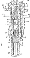
- the tubular base body 2 has, on its external face, a connection thread 5, and, on its internal face, a longitudinal groove 6.
- a bracket 7 is retained 'inside the body base 2 by a screw 8, passing through the shoulder 3, the base body 2, and received in a threaded passage 9 formed in the square 7.
- the square 7 is surrounded by two elastic metal clips 10 housed in chambers 11 machined inside the base body 2.
- Each clip 10 has ends 12 bent in the shape of a heel 13, and the ends 12 are folded inwards from the bracket 7.
- the tubular base body 2 can receive a plug 14 carrying a connection nut 15 which, by screwing on the thread 5 of the base body 2, ensures the fixing of the plug 14 on the base 1
- the plug 14 comprises a plug body 16, consisting of a shoulder 17 for retaining the connection nut 15, on either side of which there are two tubular portions 18 and 19, one of which 18 is intended to receive means for retaining a sheath 20 surrounding an optical fiber 21, and a cable 22 for mechanical protection of the sheath 20, and the other of which 19, is intended to accommodate an end piece 23 and a spring 24
- the sheath retaining means 20 consist of a cable gland 25 having a central bore 26 and disposed between two washers 27 and 28, one of which 28 is applied against the internal shoulder 29 of the plug body 16.
- the cable retaining means 22 are constituted by a ferrule 30 to be crimped or crimped around the cable 22 and one end of which é 31 is clamped between the washer 27 and a cable clamp nut 32 which is screwed onto the internal thread 33 at the end of the tubular portion 18 of the plug body 16. By screwing the cable clamp nut 32, it simultaneously ensures the retention of the ferrule 30 crimped around the cable 22 and the compression, between the washers 27 and 28, of the cable gland 25 which encloses and retains the sheath 20.
- the end piece 23 consists of a hollow base 34 , crossed by a stripped part of the optical fiber 21, and carrying a barrel 35 of square or rectangular section, with chamfered edges, having a longitudinal bore 36 into which opens an end slot 37, the end of the optical fiber that 21 being received in the longitudinal bore 36 of the barrel 35 and being immobilized at its end by a block of glue 48, previously introduced by the slot 37, as will be explained below.
- the end piece 23 is mounted in the plug body 16 so that the base 34 is received in the tubular portion 19 and that the barrel 35 passes through a bottom 38 "of the plug body 16, the base 34 being capable of sliding in the tubular portion 19 against the spring 24, bearing, on one side, against the washer 28, and, on the other, against the annular stop 40 of a sleeve 39 traversed by the fiber 21, received in the free end of the base 34 of the end piece 23, and acting as a stroke limiter for the recoil movements of the end piece 23 in the plug body 16, which, if they were too great, especially during handling of the plug 14 before connection to the base 1, would lead to overloads and excessive buckling of the part of the fiber 21 located in the base 34, which may lead to breakage of the fiber 21 or to development on the micro-bending fiber providing insertion losses.
- the plug body 16 also comprises, on its tubular portion 19, a housing 41 for a key 42.
- the barrels 35 thus come exactly at the end of one another and , by screwing the connection nuts 15 onto the threads 5 of the base 1, the barrels 35 are applied against each other with sufficient pressure to ensure good transmission between the ends of the fibers 21, the elastic recoil of the end pieces 23 in the plug body 16 avoiding contact overpressures, which would be harmful to the fibers 21.
- the particular device intended to allow the mounting of an optical fiber 21 on the barrel 35 of a tip received in a plug 14 of the connector described with reference to FIGS. 1 to 5, consists of a block 50, in which two planes 51 and 52 have been corrected perpendicular to one another, constituting a square against which a centering block 53 applies a centering element 54, the block 53 itself being held on the block 50 by the support 55 which can be secured to the latter.
- the block 50 is crossed by two guide bars 56, parallel to the edge of the bracket, and on which a plug 14 can be placed on which the cable clamp nut 32 retains the cable 22, surrounding the sheath 20, retained by the cable gland 25, of the fiber 21, which emerges from the barrel 35 of the end piece received in the plug 14, passes through a V-shaped groove 57 formed on the centering element 54, and is retained on the base 58 of a fiber-carrying element, having a: V 59, in the extension of the groove 57, by a finger 60, rocking on the base 58, and provided with a pad 61 clamping the fiber 21 against the base 58 when the finger 60 is secured to the base 58, which is sliding mounted on the two guide bars 56, and is elastically separated from the block 50 by two springs 62 mounted on the guide bars 56 and pressing against the block 50.
- springs 62 constitute elastic means tending to pull the fiber 21 out of the barrel 35.
- the plug 14 having been moved towards the block 50 on the bars 56, until the end of the barrel 35, having slid on the rectified plane 52, is in contact with the side of the element centering 54, the arm 63, pivotally mounted on the block 50, is then secured to the block 50 to apply the c anon 35 against the rectified planes 51 and 52 and give it a suitable position against the square, in contact with the centering element 54.
- the fiber 21 being held at the bottom of the groove 57 by a pressure needle 64, slidingly mounted on the block 50, between the latter and the support 55, and elastically urged by the leaf spring 65 towards the centering element 54, it is then possible to bond the fiber 21 to the barrel 35 by introducing a drop of glue in the slot 37 made at the end of the barrel 35. After drying, the fiber 21 can be released from the fiber holder and remove the plug 14 to cut the fiber 21 in line with the end of the barrel 35.
- a pressure needle 64 slidingly mounted on the block 50, between the latter and the support 55, and elastically urged by the leaf spring 65 towards the centering element 54
- each tubular end of the base body may have three grooves 6 at 120 °, two of them, at the "left” end, receiving two keys 42 of a "left” plug body, then that two grooves of the "right” end, one of which is not located in the extension of the two grooves 6 occupied by the "left” end, receive two keys 42 of a straight plug body.
- the device for mounting fibers on end caps allows the use tion of connectors according to the invention, of easy implementation and simple structure, each time that fiber to fiber connections will have to be made.
Landscapes
- Physics & Mathematics (AREA)
- General Physics & Mathematics (AREA)
- Optics & Photonics (AREA)
- Mechanical Coupling Of Light Guides (AREA)
Applications Claiming Priority (2)
| Application Number | Priority Date | Filing Date | Title |
|---|---|---|---|
| FR7830104 | 1978-10-23 | ||
| FR7830104A FR2440008A1 (fr) | 1978-10-23 | 1978-10-23 | Connecteur pour fibres optiques et dispositif de montage des fibres sur des embouts directement utilisables sur connecteur |
Publications (1)
| Publication Number | Publication Date |
|---|---|
| EP0010505A1 true EP0010505A1 (de) | 1980-04-30 |
Family
ID=9214053
Family Applications (1)
| Application Number | Title | Priority Date | Filing Date |
|---|---|---|---|
| EP79400775A Ceased EP0010505A1 (de) | 1978-10-23 | 1979-10-19 | Stecker für optische Fasern und Vorrichtung zum Einbau der Fasern in Zwingen, die direkt im Stecker benutzt werden |
Country Status (5)
| Country | Link |
|---|---|
| US (1) | US4309071A (de) |
| EP (1) | EP0010505A1 (de) |
| JP (1) | JPS5559416A (de) |
| CA (1) | CA1123243A (de) |
| FR (1) | FR2440008A1 (de) |
Cited By (5)
| Publication number | Priority date | Publication date | Assignee | Title |
|---|---|---|---|---|
| EP0045271B1 (de) * | 1980-07-30 | 1985-06-26 | RADIALL INDUSTRIE, Société Anonyme dite: | Verbindung für optische Fasern |
| EP0070980B1 (de) * | 1981-07-30 | 1985-12-04 | ANT Nachrichtentechnik GmbH | Zwitterstecker für Lichtwellenleiterkabel |
| EP0400732A3 (de) * | 1989-05-31 | 1991-11-06 | Alcatel Kabel AG & Co. | Verbindungsstecker für einen Lichtwellenleiter |
| CN105044855A (zh) * | 2015-06-28 | 2015-11-11 | 中航光电科技股份有限公司 | 一种光纤接触件定位壳 |
| CN115267979A (zh) * | 2022-08-04 | 2022-11-01 | 付敏 | 一种光纤连接器 |
Families Citing this family (20)
| Publication number | Priority date | Publication date | Assignee | Title |
|---|---|---|---|---|
| FR2473733A1 (fr) * | 1980-01-11 | 1981-07-17 | Commissariat Energie Atomique | Connecteur pour fibres optiques |
| US4784455A (en) * | 1982-03-17 | 1988-11-15 | Thomas & Betts Corporation | Strain relief connector for optical fiber |
| US4699454A (en) * | 1984-03-29 | 1987-10-13 | American Telephone And Telegraph Company, At&T Bell Laboratories | Fiber optic connector |
| US4725120A (en) * | 1984-10-25 | 1988-02-16 | American Telephone And Telegraph Company, At&T Bell Laboratories | Connector apparatus |
| JP3022015U (ja) * | 1995-08-24 | 1996-03-12 | モレックス インコーポレーテッド | 光ファイバーケーブル用コネクタ |
| US6758599B2 (en) * | 2001-03-12 | 2004-07-06 | Steris Inc. | Optical commutator |
| JP4544928B2 (ja) * | 2004-07-16 | 2010-09-15 | スリーエム イノベイティブ プロパティズ カンパニー | 光コネクタ及び光ファイバ接続システム |
| DE102006062695B4 (de) * | 2006-05-16 | 2008-05-08 | Roland Berger | Steckverbinder für einen Lichtwellenleiter |
| US7775726B2 (en) | 2007-02-16 | 2010-08-17 | 3M Innovative Properties Company | Remote grip optical fiber connector |
| US7534050B2 (en) | 2007-04-13 | 2009-05-19 | Adc Telecommunications, Inc. | Field terminatable fiber optic connector assembly |
| CN102439502B (zh) * | 2009-04-06 | 2015-02-18 | Adc电信公司 | 光纤连接器和组装方法 |
| CN102472872B (zh) * | 2009-08-10 | 2014-08-27 | 日本电信电话株式会社 | 光连接器及其组装方法 |
| US8702323B2 (en) | 2011-03-15 | 2014-04-22 | Adc Telecommunications, Inc. | Strain relief boot for a fiber optic connector |
| US8636425B2 (en) | 2011-03-15 | 2014-01-28 | Adc Telecommunications, Inc. | Fiber optic connector |
| CN104364686B (zh) | 2012-02-07 | 2016-11-16 | 泰科电子瑞侃有限公司 | 用于连接器的线缆端接组件和方法 |
| US9176285B2 (en) | 2012-05-03 | 2015-11-03 | Adc Telecommunications, Inc. | Fiber optic connector |
| WO2017081306A1 (en) * | 2015-11-13 | 2017-05-18 | CommScope Connectivity Belgium BVBA | Fiber optic connection system |
| CN113917629B (zh) * | 2021-09-28 | 2023-05-16 | 中航光电科技股份有限公司 | 一种水密光电转换连接器及水密光缆组件 |
| CN114226182B (zh) * | 2021-11-26 | 2023-07-14 | 上海航天控制技术研究所 | 一种用于圆形截面管梁的光纤应变传感器铺设定位装置 |
| CN115503339B (zh) * | 2022-09-30 | 2024-09-03 | 湖北中北博睿科技有限公司 | 一种紫外光固化油墨的固化装置 |
Citations (2)
| Publication number | Priority date | Publication date | Assignee | Title |
|---|---|---|---|---|
| DE2456151A1 (de) * | 1974-11-27 | 1976-08-12 | Siemens Ag | Steckverbindung fuer optische glasfasern |
| GB1526260A (en) * | 1976-12-14 | 1978-09-27 | Standard Telephones Cables Ltd | Connectors |
Family Cites Families (10)
| Publication number | Priority date | Publication date | Assignee | Title |
|---|---|---|---|---|
| US3999841A (en) * | 1974-08-19 | 1976-12-28 | Gte Laboratories Incorporated | Method for forming an optical fiber connector |
| US3936145A (en) * | 1974-11-07 | 1976-02-03 | International Telephone And Telegraph Corporation | Fiber optic alignment sleeve |
| GB1460548A (en) * | 1975-11-20 | 1977-01-06 | Standard Telephones Cables Ltd | Optical fibre terminations and connectors |
| GB1577729A (en) * | 1976-09-25 | 1980-10-29 | Plessey Co Ltd | Coupling of optic-waveguide elements |
| US4140367A (en) * | 1976-10-08 | 1979-02-20 | Bunker Ramo Corporation | Multiple channel connector for fiber optic cables |
| GB1571942A (en) * | 1977-03-24 | 1980-07-23 | Cannon Electric Great Britain | Fibre optic connector |
| US4192056A (en) * | 1977-12-14 | 1980-03-11 | Thomas & Betts Corporation | Assembly tool |
| US4158476A (en) * | 1977-12-16 | 1979-06-19 | International Telephone And Telegraph Corporation | Single optical fiber connector |
| US4190316A (en) * | 1978-02-02 | 1980-02-26 | The Deutsch Company | Lens connector for optical fibers |
| US4218113A (en) * | 1978-08-21 | 1980-08-19 | International Business Machines Corporation | Optical fiber connector apparatus |
-
1978
- 1978-10-23 FR FR7830104A patent/FR2440008A1/fr active Granted
-
1979
- 1979-10-17 US US06/085,917 patent/US4309071A/en not_active Expired - Lifetime
- 1979-10-19 EP EP79400775A patent/EP0010505A1/de not_active Ceased
- 1979-10-22 CA CA338,143A patent/CA1123243A/fr not_active Expired
- 1979-10-22 JP JP13535279A patent/JPS5559416A/ja active Pending
Patent Citations (2)
| Publication number | Priority date | Publication date | Assignee | Title |
|---|---|---|---|---|
| DE2456151A1 (de) * | 1974-11-27 | 1976-08-12 | Siemens Ag | Steckverbindung fuer optische glasfasern |
| GB1526260A (en) * | 1976-12-14 | 1978-09-27 | Standard Telephones Cables Ltd | Connectors |
Cited By (6)
| Publication number | Priority date | Publication date | Assignee | Title |
|---|---|---|---|---|
| EP0045271B1 (de) * | 1980-07-30 | 1985-06-26 | RADIALL INDUSTRIE, Société Anonyme dite: | Verbindung für optische Fasern |
| EP0070980B1 (de) * | 1981-07-30 | 1985-12-04 | ANT Nachrichtentechnik GmbH | Zwitterstecker für Lichtwellenleiterkabel |
| EP0400732A3 (de) * | 1989-05-31 | 1991-11-06 | Alcatel Kabel AG & Co. | Verbindungsstecker für einen Lichtwellenleiter |
| CN105044855A (zh) * | 2015-06-28 | 2015-11-11 | 中航光电科技股份有限公司 | 一种光纤接触件定位壳 |
| CN115267979A (zh) * | 2022-08-04 | 2022-11-01 | 付敏 | 一种光纤连接器 |
| CN115267979B (zh) * | 2022-08-04 | 2023-09-22 | 上海信管网络科技有限公司 | 一种光纤连接器 |
Also Published As
| Publication number | Publication date |
|---|---|
| CA1123243A (fr) | 1982-05-11 |
| US4309071A (en) | 1982-01-05 |
| JPS5559416A (en) | 1980-05-02 |
| FR2440008A1 (fr) | 1980-05-23 |
| FR2440008B1 (de) | 1982-06-18 |
Similar Documents
| Publication | Publication Date | Title |
|---|---|---|
| CA1123243A (fr) | Connecteur pour fibres optiques et dispositif de montage des fibres sur des embouts directement utilisables sur connecteur | |
| US4684205A (en) | Fiber optic connector with compensating mechanism | |
| EP0051519B1 (de) | Zwinge für einen Verbinder für optische Fasern und Verbinder mit einer solchen Zwinge | |
| US4687288A (en) | Fiber optic connector with temperature compensating mechanism | |
| US5414790A (en) | Actuation tool and cap for fiber optic connector | |
| RU2460100C2 (ru) | Держатель, устройство для сращивания сплавлением и способ сборки оптического коннектора | |
| JP5599435B2 (ja) | 可逆成端可能な光ファイバコネクタ | |
| US4127319A (en) | Termination means for fiber optic bundle | |
| EP0097575B1 (de) | Stecker für faseroptisches Verbindungsstück und Verbindungsstück mit solchem Stecker | |
| FR2506033A1 (fr) | Connexion a enficher destinee a coupler au moins une fibre conductrice de lumiere a un autre element optique | |
| FR2547424A1 (fr) | Connecteur optique, procede de fabrication dudit connecteur et connexions fibres - fibres et diodes - fibres realisees avec ce connecteur | |
| CA1247419A (en) | Optical fiber connector | |
| CA1089685A (fr) | Connecteur a elements auto-centreurs pour conducteurs optiques | |
| CA1087007A (fr) | Connecteur pour liaison a fibre optique | |
| EP0282766A1 (de) | Aktives optisches Steckergehäuse | |
| US4718745A (en) | Optical fiber connector | |
| FR2518762A1 (fr) | Organe de fermeture mobile pour elements optiques | |
| FR2466028A1 (fr) | Connecteurs pour fibres optiques | |
| CA2819238A1 (en) | Field-installable fiber optic connectors and related cable assemblies | |
| FR2588387A1 (fr) | Element de connecteur hermaphrodite pour fibres optiques | |
| EP0014610A1 (de) | Lösbare Verbindungsvorrichtung für optische Fasern | |
| US20200249401A1 (en) | Connector assemblies for hybrid fiber/wire connections | |
| JP2005114770A (ja) | 光コネクタ | |
| EP0036369A1 (de) | Verfahren und Vorrichtung zum Verbinden faseroptischer Kabel auf dem Arbeitsplatz | |
| EP0010507A1 (de) | Stecker zum Verbinden einer optischen Faser und einer Photodiode |
Legal Events
| Date | Code | Title | Description |
|---|---|---|---|
| PUAI | Public reference made under article 153(3) epc to a published international application that has entered the european phase |
Free format text: ORIGINAL CODE: 0009012 |
|
| AK | Designated contracting states |
Designated state(s): BE DE GB IT NL |
|
| 17P | Request for examination filed | ||
| STAA | Information on the status of an ep patent application or granted ep patent |
Free format text: STATUS: THE APPLICATION HAS BEEN REFUSED |
|
| 18R | Application refused |
Effective date: 19830331 |
|
| RIN1 | Information on inventor provided before grant (corrected) |
Inventor name: PRUNIER, JEAN-CLAUDE |