EP0010699A1 - Steuerung für Hydraulikmotoren mit schnell ansprechendem Eilgangventil - Google Patents
Steuerung für Hydraulikmotoren mit schnell ansprechendem Eilgangventil Download PDFInfo
- Publication number
- EP0010699A1 EP0010699A1 EP19790104041 EP79104041A EP0010699A1 EP 0010699 A1 EP0010699 A1 EP 0010699A1 EP 19790104041 EP19790104041 EP 19790104041 EP 79104041 A EP79104041 A EP 79104041A EP 0010699 A1 EP0010699 A1 EP 0010699A1
- Authority
- EP
- European Patent Office
- Prior art keywords
- valve
- fluid
- port
- pilot
- quick
- Prior art date
- Legal status (The legal status is an assumption and is not a legal conclusion. Google has not performed a legal analysis and makes no representation as to the accuracy of the status listed.)
- Granted
Links
- 239000012530 fluid Substances 0.000 title claims abstract description 119
- 238000007599 discharging Methods 0.000 claims description 8
- 230000000903 blocking effect Effects 0.000 claims description 6
- 230000004044 response Effects 0.000 claims description 6
- 230000037361 pathway Effects 0.000 claims 6
- 230000005484 gravity Effects 0.000 abstract description 16
- 230000000694 effects Effects 0.000 description 15
- 230000002411 adverse Effects 0.000 description 7
- 230000008901 benefit Effects 0.000 description 3
- 230000006835 compression Effects 0.000 description 3
- 238000007906 compression Methods 0.000 description 3
- 230000009471 action Effects 0.000 description 2
- 230000007246 mechanism Effects 0.000 description 2
- 230000004048 modification Effects 0.000 description 2
- 238000012986 modification Methods 0.000 description 2
- 239000013589 supplement Substances 0.000 description 2
- 238000009825 accumulation Methods 0.000 description 1
- 230000008859 change Effects 0.000 description 1
- 230000003100 immobilizing effect Effects 0.000 description 1
- 239000011800 void material Substances 0.000 description 1
Images

Classifications
-
- E—FIXED CONSTRUCTIONS
- E02—HYDRAULIC ENGINEERING; FOUNDATIONS; SOIL SHIFTING
- E02F—DREDGING; SOIL-SHIFTING
- E02F3/00—Dredgers; Soil-shifting machines
- E02F3/04—Dredgers; Soil-shifting machines mechanically-driven
- E02F3/76—Graders, bulldozers, or the like with scraper plates or ploughshare-like elements; Levelling scarifying devices
- E02F3/80—Component parts
- E02F3/84—Drives or control devices therefor, e.g. hydraulic drive systems
- E02F3/844—Drives or control devices therefor, e.g. hydraulic drive systems for positioning the blade, e.g. hydraulically
-
- F—MECHANICAL ENGINEERING; LIGHTING; HEATING; WEAPONS; BLASTING
- F15—FLUID-PRESSURE ACTUATORS; HYDRAULICS OR PNEUMATICS IN GENERAL
- F15B—SYSTEMS ACTING BY MEANS OF FLUIDS IN GENERAL; FLUID-PRESSURE ACTUATORS, e.g. SERVOMOTORS; DETAILS OF FLUID-PRESSURE SYSTEMS, NOT OTHERWISE PROVIDED FOR
- F15B11/00—Servomotor systems without provision for follow-up action; Circuits therefor
- F15B11/02—Systems essentially incorporating special features for controlling the speed or actuating force of an output member
- F15B11/024—Systems essentially incorporating special features for controlling the speed or actuating force of an output member by means of differential connection of the servomotor lines, e.g. regenerative circuits
-
- F—MECHANICAL ENGINEERING; LIGHTING; HEATING; WEAPONS; BLASTING
- F15—FLUID-PRESSURE ACTUATORS; HYDRAULICS OR PNEUMATICS IN GENERAL
- F15B—SYSTEMS ACTING BY MEANS OF FLUIDS IN GENERAL; FLUID-PRESSURE ACTUATORS, e.g. SERVOMOTORS; DETAILS OF FLUID-PRESSURE SYSTEMS, NOT OTHERWISE PROVIDED FOR
- F15B13/00—Details of servomotor systems ; Valves for servomotor systems
- F15B13/02—Fluid distribution or supply devices characterised by their adaptation to the control of servomotors
- F15B13/021—Valves for interconnecting the fluid chambers of an actuator
-
- F—MECHANICAL ENGINEERING; LIGHTING; HEATING; WEAPONS; BLASTING
- F15—FLUID-PRESSURE ACTUATORS; HYDRAULICS OR PNEUMATICS IN GENERAL
- F15B—SYSTEMS ACTING BY MEANS OF FLUIDS IN GENERAL; FLUID-PRESSURE ACTUATORS, e.g. SERVOMOTORS; DETAILS OF FLUID-PRESSURE SYSTEMS, NOT OTHERWISE PROVIDED FOR
- F15B11/00—Servomotor systems without provision for follow-up action; Circuits therefor
- F15B11/02—Systems essentially incorporating special features for controlling the speed or actuating force of an output member
- F15B11/024—Systems essentially incorporating special features for controlling the speed or actuating force of an output member by means of differential connection of the servomotor lines, e.g. regenerative circuits
- F15B2011/0243—Systems essentially incorporating special features for controlling the speed or actuating force of an output member by means of differential connection of the servomotor lines, e.g. regenerative circuits the regenerative circuit being activated or deactivated automatically
-
- F—MECHANICAL ENGINEERING; LIGHTING; HEATING; WEAPONS; BLASTING
- F15—FLUID-PRESSURE ACTUATORS; HYDRAULICS OR PNEUMATICS IN GENERAL
- F15B—SYSTEMS ACTING BY MEANS OF FLUIDS IN GENERAL; FLUID-PRESSURE ACTUATORS, e.g. SERVOMOTORS; DETAILS OF FLUID-PRESSURE SYSTEMS, NOT OTHERWISE PROVIDED FOR
- F15B11/00—Servomotor systems without provision for follow-up action; Circuits therefor
- F15B11/02—Systems essentially incorporating special features for controlling the speed or actuating force of an output member
- F15B11/024—Systems essentially incorporating special features for controlling the speed or actuating force of an output member by means of differential connection of the servomotor lines, e.g. regenerative circuits
- F15B2011/0246—Systems essentially incorporating special features for controlling the speed or actuating force of an output member by means of differential connection of the servomotor lines, e.g. regenerative circuits with variable regeneration flow
-
- F—MECHANICAL ENGINEERING; LIGHTING; HEATING; WEAPONS; BLASTING
- F15—FLUID-PRESSURE ACTUATORS; HYDRAULICS OR PNEUMATICS IN GENERAL
- F15B—SYSTEMS ACTING BY MEANS OF FLUIDS IN GENERAL; FLUID-PRESSURE ACTUATORS, e.g. SERVOMOTORS; DETAILS OF FLUID-PRESSURE SYSTEMS, NOT OTHERWISE PROVIDED FOR
- F15B2211/00—Circuits for servomotor systems
- F15B2211/30—Directional control
- F15B2211/305—Directional control characterised by the type of valves
- F15B2211/30525—Directional control valves, e.g. 4/3-directional control valve
-
- F—MECHANICAL ENGINEERING; LIGHTING; HEATING; WEAPONS; BLASTING
- F15—FLUID-PRESSURE ACTUATORS; HYDRAULICS OR PNEUMATICS IN GENERAL
- F15B—SYSTEMS ACTING BY MEANS OF FLUIDS IN GENERAL; FLUID-PRESSURE ACTUATORS, e.g. SERVOMOTORS; DETAILS OF FLUID-PRESSURE SYSTEMS, NOT OTHERWISE PROVIDED FOR
- F15B2211/00—Circuits for servomotor systems
- F15B2211/30—Directional control
- F15B2211/305—Directional control characterised by the type of valves
- F15B2211/3056—Assemblies of multiple valves
- F15B2211/30565—Assemblies of multiple valves having multiple valves for a single output member, e.g. for creating higher valve function by use of multiple valves like two 2/2-valves replacing a 5/3-valve
- F15B2211/3058—Assemblies of multiple valves having multiple valves for a single output member, e.g. for creating higher valve function by use of multiple valves like two 2/2-valves replacing a 5/3-valve having additional valves for interconnecting the fluid chambers of a double-acting actuator, e.g. for regeneration mode or for floating mode
-
- F—MECHANICAL ENGINEERING; LIGHTING; HEATING; WEAPONS; BLASTING
- F15—FLUID-PRESSURE ACTUATORS; HYDRAULICS OR PNEUMATICS IN GENERAL
- F15B—SYSTEMS ACTING BY MEANS OF FLUIDS IN GENERAL; FLUID-PRESSURE ACTUATORS, e.g. SERVOMOTORS; DETAILS OF FLUID-PRESSURE SYSTEMS, NOT OTHERWISE PROVIDED FOR
- F15B2211/00—Circuits for servomotor systems
- F15B2211/30—Directional control
- F15B2211/31—Directional control characterised by the positions of the valve element
- F15B2211/3105—Neutral or centre positions
- F15B2211/3116—Neutral or centre positions the pump port being open in the centre position, e.g. so-called open centre
-
- F—MECHANICAL ENGINEERING; LIGHTING; HEATING; WEAPONS; BLASTING
- F15—FLUID-PRESSURE ACTUATORS; HYDRAULICS OR PNEUMATICS IN GENERAL
- F15B—SYSTEMS ACTING BY MEANS OF FLUIDS IN GENERAL; FLUID-PRESSURE ACTUATORS, e.g. SERVOMOTORS; DETAILS OF FLUID-PRESSURE SYSTEMS, NOT OTHERWISE PROVIDED FOR
- F15B2211/00—Circuits for servomotor systems
- F15B2211/30—Directional control
- F15B2211/31—Directional control characterised by the positions of the valve element
- F15B2211/3122—Special positions other than the pump port being connected to working ports or the working ports being connected to the return line
- F15B2211/3127—Floating position connecting the working ports and the return line
-
- F—MECHANICAL ENGINEERING; LIGHTING; HEATING; WEAPONS; BLASTING
- F15—FLUID-PRESSURE ACTUATORS; HYDRAULICS OR PNEUMATICS IN GENERAL
- F15B—SYSTEMS ACTING BY MEANS OF FLUIDS IN GENERAL; FLUID-PRESSURE ACTUATORS, e.g. SERVOMOTORS; DETAILS OF FLUID-PRESSURE SYSTEMS, NOT OTHERWISE PROVIDED FOR
- F15B2211/00—Circuits for servomotor systems
- F15B2211/30—Directional control
- F15B2211/31—Directional control characterised by the positions of the valve element
- F15B2211/3144—Directional control characterised by the positions of the valve element the positions being continuously variable, e.g. as realised by proportional valves
-
- F—MECHANICAL ENGINEERING; LIGHTING; HEATING; WEAPONS; BLASTING
- F15—FLUID-PRESSURE ACTUATORS; HYDRAULICS OR PNEUMATICS IN GENERAL
- F15B—SYSTEMS ACTING BY MEANS OF FLUIDS IN GENERAL; FLUID-PRESSURE ACTUATORS, e.g. SERVOMOTORS; DETAILS OF FLUID-PRESSURE SYSTEMS, NOT OTHERWISE PROVIDED FOR
- F15B2211/00—Circuits for servomotor systems
- F15B2211/30—Directional control
- F15B2211/315—Directional control characterised by the connections of the valve or valves in the circuit
- F15B2211/3157—Directional control characterised by the connections of the valve or valves in the circuit being connected to a pressure source, an output member and a return line
- F15B2211/31576—Directional control characterised by the connections of the valve or valves in the circuit being connected to a pressure source, an output member and a return line having a single pressure source and a single output member
-
- F—MECHANICAL ENGINEERING; LIGHTING; HEATING; WEAPONS; BLASTING
- F15—FLUID-PRESSURE ACTUATORS; HYDRAULICS OR PNEUMATICS IN GENERAL
- F15B—SYSTEMS ACTING BY MEANS OF FLUIDS IN GENERAL; FLUID-PRESSURE ACTUATORS, e.g. SERVOMOTORS; DETAILS OF FLUID-PRESSURE SYSTEMS, NOT OTHERWISE PROVIDED FOR
- F15B2211/00—Circuits for servomotor systems
- F15B2211/30—Directional control
- F15B2211/32—Directional control characterised by the type of actuation
- F15B2211/321—Directional control characterised by the type of actuation mechanically
- F15B2211/324—Directional control characterised by the type of actuation mechanically manually, e.g. by using a lever or pedal
-
- F—MECHANICAL ENGINEERING; LIGHTING; HEATING; WEAPONS; BLASTING
- F15—FLUID-PRESSURE ACTUATORS; HYDRAULICS OR PNEUMATICS IN GENERAL
- F15B—SYSTEMS ACTING BY MEANS OF FLUIDS IN GENERAL; FLUID-PRESSURE ACTUATORS, e.g. SERVOMOTORS; DETAILS OF FLUID-PRESSURE SYSTEMS, NOT OTHERWISE PROVIDED FOR
- F15B2211/00—Circuits for servomotor systems
- F15B2211/40—Flow control
- F15B2211/405—Flow control characterised by the type of flow control means or valve
- F15B2211/40507—Flow control characterised by the type of flow control means or valve with constant throttles or orifices
-
- F—MECHANICAL ENGINEERING; LIGHTING; HEATING; WEAPONS; BLASTING
- F15—FLUID-PRESSURE ACTUATORS; HYDRAULICS OR PNEUMATICS IN GENERAL
- F15B—SYSTEMS ACTING BY MEANS OF FLUIDS IN GENERAL; FLUID-PRESSURE ACTUATORS, e.g. SERVOMOTORS; DETAILS OF FLUID-PRESSURE SYSTEMS, NOT OTHERWISE PROVIDED FOR
- F15B2211/00—Circuits for servomotor systems
- F15B2211/40—Flow control
- F15B2211/415—Flow control characterised by the connections of the flow control means in the circuit
- F15B2211/41527—Flow control characterised by the connections of the flow control means in the circuit being connected to an output member and a directional control valve
-
- F—MECHANICAL ENGINEERING; LIGHTING; HEATING; WEAPONS; BLASTING
- F15—FLUID-PRESSURE ACTUATORS; HYDRAULICS OR PNEUMATICS IN GENERAL
- F15B—SYSTEMS ACTING BY MEANS OF FLUIDS IN GENERAL; FLUID-PRESSURE ACTUATORS, e.g. SERVOMOTORS; DETAILS OF FLUID-PRESSURE SYSTEMS, NOT OTHERWISE PROVIDED FOR
- F15B2211/00—Circuits for servomotor systems
- F15B2211/50—Pressure control
- F15B2211/575—Pilot pressure control
-
- F—MECHANICAL ENGINEERING; LIGHTING; HEATING; WEAPONS; BLASTING
- F15—FLUID-PRESSURE ACTUATORS; HYDRAULICS OR PNEUMATICS IN GENERAL
- F15B—SYSTEMS ACTING BY MEANS OF FLUIDS IN GENERAL; FLUID-PRESSURE ACTUATORS, e.g. SERVOMOTORS; DETAILS OF FLUID-PRESSURE SYSTEMS, NOT OTHERWISE PROVIDED FOR
- F15B2211/00—Circuits for servomotor systems
- F15B2211/70—Output members, e.g. hydraulic motors or cylinders or control therefor
- F15B2211/75—Control of speed of the output member
-
- F—MECHANICAL ENGINEERING; LIGHTING; HEATING; WEAPONS; BLASTING
- F15—FLUID-PRESSURE ACTUATORS; HYDRAULICS OR PNEUMATICS IN GENERAL
- F15B—SYSTEMS ACTING BY MEANS OF FLUIDS IN GENERAL; FLUID-PRESSURE ACTUATORS, e.g. SERVOMOTORS; DETAILS OF FLUID-PRESSURE SYSTEMS, NOT OTHERWISE PROVIDED FOR
- F15B2211/00—Circuits for servomotor systems
- F15B2211/80—Other types of control related to particular problems or conditions
- F15B2211/86—Control during or prevention of abnormal conditions
- F15B2211/8609—Control during or prevention of abnormal conditions the abnormal condition being cavitation
Definitions
- This invention relates to control systems for fluid pressure-operated motors, such as fluid cylinders, fluid actuators or the like, and more particularly to a quick-drop valve which enables fast gravity-assisted lowering of a load or member by directing fluid which discharges from one motor port back to the other motor port.
- Control systems for fluid cylinders or the like usually have a main control valve connected between the cylinder and a pump or other source of pressurized.fluid.
- the main control valve has a raise position at which pressurized fluid is supplied to the rod end of the cylinder and at which fluid is discharged from the head end in order to move a load against gravity or against some other resistance.
- the rate of cylinder retraction is determined by the rate at which the pump forces fluid into the cylinder. This is not necessarily the case when the main control valve is shifted to the lower or power-down position at which the pressurized fluid is applied to the head end of the cylinder and at which fluid discharges from the rod end back to tank.
- gravity or other forces may be capable of causing a rate of cylinder extension exceeding that established by the rate of flow of pressurized fluid to the head end of the cylinder. Severe negative pressures or cavitation may then cause a loss of precision in controlling the cylinder.
- the cylinder may not respond quickly to shifts of the control valve and other adverse effects occur such as erratic cylinder motion and vibration and bounce or temporary reversals of cylinder motion. While these effects can be avoided by restricting the rate at which fluid can discharge back to tank through the main control valve at the power-down position of the valve, this may undesirably limit the rate of lowering of the load.
- quick-drop valves To enable fast lowering of a load, a variety of quick-drop valves have heretofore been designed for connection between the two flow passages to the ends of the cylinder at a location relatively close to the cylinder and in some cases as a built-in component of the cylinder itself.
- Quick-drop valves provide a relatively short and low resistance fluid interchange path between the two ends of the cylinder that remains closed during the raise mode of operation but which is opened during gravity-assisted lowering of the load so that fluid which is discharging from one cylinder port is directed to the other port to supplement the incoming flow from the main control valve.
- the quick-drop valve senses cavitation in the cylinder during the power-down mode of operation and opens automatically while such condition is present.
- Prior quick-drop valves of known forms are subject to certain operational disadvantages. Many prior quick-drop valves operate in response to a discharge pressure differential across a restriction in the flow path which connects the discharging end of the cylinder with the tank through the main control valve. Consequently the discharge flow path must remain at least partially open and part of the discharge flow must be returned to tank during the quick-drop mode of operation instead of being recirculated to the head end to inhibit cavitation. Some other prior quick-drop valves respond to a flow restriction situated in the flow path to the pressurized end of the cylinder, but in these cases the discharging flow path remains communicated with tank during the quick-drop mode of operation again preventing use of the entire discharge flow for the purpose of enabling fast lowering of a load without adverse effects.
- the prior art has not provided a quick-drop valve which fully seals off the rod end flow passage from tank during the quick-drop mode of operation and which.fully returns all discharge fluid to the head end of the cylinder at that time.
- the present invention is directed to overcoming one or more of the problems as set forth above.
- the control system for one or more fluid cylinders or other fluid motors includes quick-drop valve means which shifts from a power-down mode of operation into a quick-drop mode upon sensing cavitation accompanied by a fluid flow into the cylinder which is above a predetermined level.
- the quick-drop valve means then completely blocks the discharge flow path from the cylinder back to tank in order to recirculate all discharge fluid directly back to the cylinder. This total regeneraiion of the discharge flow enables an extremely fast gravity lowering of a load without adverse effects.
- the quick-drop valve means Upon sensing resistance to continued lowering of the load the quick-drop valve means automatically reverts to the power-down mode of operation rapidly and without bounce or other adverse effects, enabling continued lowering of the load without any significant interruption.
- the quick-drop valve means is biased towards a normal position at which the two-flow passages to the cylinder or the like are isolated from each other and separately communicated with the main control valve to enable raise, hold and power-down modes of operation to be selected by manipulation of the main control valve.
- a flow restriction is provided in the particular flow passage through which fluid is directed to the cylinder or the like during the power-down mode of operation.
- Pilot means respond to cavitation in the cylinder accompanied by a predetermined pressure differential across the flow restriction by shifting the quick-drop valve to an alternate position at which the discharge flow passage back to the main control valve is completely blocked and at which all discharge fluid is recirculated back to the cylinder or the like to supplement the flow arriving from the main control valve.
- the pilot means also respond to either or both of a drop of the pressure differential across the flow restriction and a cessation of cylinder cavitation by quickly resetting the quick-drop valve back to the power-down position.
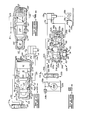
- a fluid circuit 11 includes a quick-drop valve means 12 for controlling a fluid motor 13 that has first and second motor ports 14 and 17 respectively each of which may receive or discharge fluid depending on the direction of motor motion.
- Motor 13 in this example is a fluid cylinder 13a in which the first motor port is a rod end port 14a to which pressurized fluid is directed to cause cylinder retraction and consequent raising of a load 16 and in which the second motor port is a head end port 17a to which the pressurized fluid may be directed to cause extension of the cylinder and lowering of the load.
- the load l6 in this particular example is a bulldozer blade 18 coupled to the body of a tractor 19 through vertically pivotable push arms 21 to which the rod of cylinder 13a is coupled.
- the cylinder 13a may be caused to retract to raise the blade 18 against gravity.
- Lowering of the blade l8 may be accomplished by directing pressurized fluid to head end port 17a while allowing fluid to discharge from rod end port 14a, but in this case two distinct modes of cylinder extension are possible.
- the rate of cylinder extension is primarily determined by the rate at which pressurized fluid is directed into head end port 17a and the system is in the power-down mode of operation. Under other conditions, such as when the lower edge of the blade l8 is above the ground, cylinder extension may tend to outrun the incoming supply of pressurized fluid and the extension rate is then determined by gravity acting against mechanical friction and whatever degree of flow resistance may be present in the discharge path from rod end port 14a.
- the quick-drop valve means 12 of circuit 11 inhibits such effects during the quick-drop mode of operation to provide for extremely fast lowering of the load and further provides for an extremely quick automatic shift into the power-down mode of operation when resistance to lowering of the load increases from contact of blade 18 with the ground 22 or other causes.
- the circuit 11 may utilize a fluid such as oil for example, stored in a tank 23, which is pressurized and delivered to a fluid inlet 25 of a main control valve 26 by a pump 24.
- Main control valve 26 also has a drain outlet 27 for returning discharge fluid to tank 23.
- a relief valve 28 is connected between the output of the pump 24 and tank 23 to establish a predetermined maximum fluid pressure and to return excess output fluid from the pump directly back to the tank.
- the main control valve 26 in this example is of the manually operated form and has four positions or settings.
- pressurized fluid is directed into a first or rod end flow path conduit 29 while a second or head end flow path conduit 31 is communicated with tank 23 through drain outlet 27.
- the main control valve 26 may be shifted to a hold position at which both flow path conduits 29 and 31 are closed at the main control valve, while inlet 25 is communicated with drain outlet 27, thereby immobilizing the cylinder 13a.
- head end flow path conduit 31 receives pressurized fluid from inlet 25 while the rod end flow path conduit 29 is communicated with drain outlet 27.
- the fourth position of the main control valve 26 is a float position at which flow path conduits 29 and 31 are intercommunicated with each other and with drain 27.
- the quick-drop valve means 12 may have a housing 32 with a bore forming a cylindrical valve chamber 33 in which a movable valve member or spool 34 is disposed.
- An annular groove 36 is formed in housing 32 and communicates with chamber 33 and with the first or rod end port 14a of cylinder 13a through a first valve port 37 and a flow line 38.
- Another spaced-apart annular groove 40 opens into chamber 33 and is communicated with the second or head end port 17a of the cylinder 13a through a second valve port 41 and head end flow line 31.
- Still another annular groove 45 opening into chamber 33 is communicated with the rod end flow path conduit 29 at a third valve port 44.
- the head end flow path conduit 31 includes a flow restriction 47 situated between the main control valve 26 and the connection to second valve port 41.
- Spool 34 is shiftable in the axial direction from a normal position depicted in Figure 1, at which the spool abuts the left end of chamber 33 as viewed in the drawings, to an alternate or quick-drop position depicted in Figure 3.
- the spool 34 has three axially spaced-apart annular lands 48, 49 and 51 of which lands 48 and 49 jointly define a broad spool groove 52 while lands 49 and 51 jointly define a second spaced-apart broad spool groove 53.
- the lands 48, 49 and 51 are positioned on the spool to cause the first and third valve ports 37 and 44 to be communicated by spool groove 53 and to be isolated from the second valve port 41, by land 49, when the spool is at the normal position depicted in Figure 1.
- spool groove 52 communicates the first and second valve ports 37 and 41 while blocking and completely closing off the third valve port 44 from each of the other valve ports.
- first and second pilot means 54 and 56 respectively situated at the left and right ends of spool 34 as viewed in Figure 1.
- the first pilot means 54 in this example is formed by the left end of valve chamber 33, spool 34 including land 48 and a first pilot signal line 57 which communicates the first pilot chamber 55 at the left end of valve chamber bore 33 with a first region 58 of the head end flow path conduit 31 which is between main control valve 26 and flow restriction 47.
- the second pilot means 56 includes a second pilot chamber 59 which is of greater diameter than the valve chamber 33 and which is within an enlarged right end section 32' of housing 32.
- a pilot piston 61 is disposed in pilot chamber 59 and is movable in the axial direction between an unactuated position at which the pilot piston abuts the right end of the pilot chamber 59 as depicted in Figure 1 and an actuated position depicted in Figure 2 at which the pilot piston abuts the left end of the pilot chamber 59.
- Biasing means in the form of a resilient compression spring 62 is disposed in valve housing 32 between spool 34 and pilot piston 61 to bias the valve spool towards the normal position while biasing the pilot piston 61 towards the unactuated position as depicted in Figure 1.
- a second pilot signal line 63 communicates the outer or right end of pilot chamber 59 with a second region 64 of the head end flow path 31 that is on the opposite side of restriction 47 from region 58.
- a drain passage 66 communicates with the opposite end of the pilot chamber 59, at the region of spring 62, to avoid accumulation of leakage fluid between the spool 3 1 1 and the pilot piston 61.
- second pilot chamber 59 including piston Gl have a larger diameter than the first pilot chamber 55 in order to prevent shifting of spool 34 to the quick-drop position until the pressure in chamber 55 exceeds that in chamber 59 by a sizable amount indicative of cavitation in the head end of cylinder 13a.
- this same effect may be realized with a second pilot chamber 59' which has the same diameter as quick-drop valve housing bore 33' if the first pilot chamber 55' has a smaller diameter.
- raising of the load 16 against gravity is initiated by shifting the main control valve 26 to the raise position depicted in Figure 1 at which pressurized fluid from pump 24 is transmitted to rod end conduit 29 and at which the head end conduit 31 is opened to drain outlet 27.
- Spring 62 holds spool 34 at the normal position since the first pilot chamber 55 is open to drain and only lightly pressurized if at all.
- a somewhat higher pressure is present in the second pilot chamber 59 owing to the pressure differential created across restriction 47 by the discharging flow. If the discharge flow is sufficiently high this may shift pilot piston 6l but the practical effect is simply to increase the spring force which is holding spool 3 1 1 at the normal position depicted in Figure 1.
- pressurized fluid from pump 24 is transmitted to the rod end port 14a of the cylinder 13a through main control valve 26, rod end conduit 29, valve ports 44 and 37 and flow line 38.
- the head end port 17a of the cylinder is open to drain outlet 27 through head end flow conduit 31 including restriction 47 and the main control valve 26.
- cylinder 13a retracts to raise the load l6.
- the main control valve 26 is of the infinitely variable form, the operator may, within limits, control the rate of raising of the load by adjusting the main control valve to regulate fluid flow rate to the cylinder.
- main control valve 26 may be shifted to the hold position at which both the rod end flow conduit 29 and the head end flow conduit 31 are blocked at the main control valve.
- the system has not been depicted in the drawings in the hold position as all components other than the main control valve 26 remain in the positions depicted in Figure 1.
- the load l6 is immobilized as fluid from rod end port 14a cannot flow back to drain owing to the closed condition of the main control valve and cannot flow into the head end of the cylinder owing to the position of land 49 which blocks first valve port 37 from second ⁇ valve port 41.
- fluid cannot flow into or out of the head end port 17a as the head end flow path conduit 31 is also blocked at the main control valve 26.
- the first and second pilot means 5 1 1 and 56 are unable to shift spool 34 or pilot piston 61. at this time since there is no flow across restriction 47 to create a pressure differential which might activate the pilot means. Additionally, the pressure within the pilot signal lines 57 and 63 tends to be low at this time as the weight of the load 16 tends to create a high-pressure condition in the rod end of cylinder 13a and a relatively low-pressure condition in the head end.
- the quick-drop valve means 12 may self-operate to either the power-down position depicted in Figure 2 or to the quick-drop position depicted in Figure 3 depending on the interrelationship between two factors.
- the first factor is the direction of the external forces acting on cylinder 13a. If external forces are such as to oppose lowering of the load, the circuit 11 assumes the power-down position depicted in Figure 2 without regard to the second factor.
- the second factor is the extent to which the operator has opened the main control valve 26 into the lower setting or, in other words, the rate at which pressurized fluid is being transmitted to the cylinder through restriction 47 and being discharged from the cylinder through the main control valve. If external forces such as gravity are acting to extend the cylinder, then the action of the circuit 11 depends on the relationship of the magnitude of the external force to the degree of opening of the main control valve 26. This action can best be understood by first considering the operation of the circuit in the power-down mode under conditions where there is external resistance to extension of the cylinder 13a or where the main control valve 26 has been opened only to a limited extent insufficient to enable the quick-drop mode of operation.
- spool 34 of the quick-drop valve 12 remains in the normal or leftward position while the pilot piston 61 is shifted to the actuated or leftward position by the second pilot means 56 as will hereinafter be discussed in more detail.
- the first and third valve ports 37 and 44 remain communicated across spool groove 53 and remain blocked from the second valve port 4l by spool land 49. Pressurized fluid is therefore supplied to the head end port 17a of cylinder 13a through head end flow conduit 31, including restriction 47.
- the rod end port 14a of the cylinder is communicated to drain outlet 27 through flow line 38, valve port 37, spool groove 53, valve port 44, rod end flow path conduit 29 and the main control valve 26.
- the resulting high fluid pressure within the head end of the cylinder extends the cylinder to forcibly lower the load against the resistance to such movement.
- Pilot piston 61 shifts to the actuated position at this time since the relatively high pressure within the head end of the cylinder 13a is transmitted to pilot chamber 59 by the second pilot signal line 63 where the pressure acts against the pilot piston 61 with a force greater than that of spring 62.
- the flow of fluid through restriction 47 creates a pressure drop thereacross causing a somewhat higher pressure to be present in the pilot chamber 55 of the first pilot means 54 than in the second pilot chamber 59 but owing to the difference in the diameters of the two pilot chambers and to the force exerted by spring 62, the pressure difference is insufficient to shift spool 34 and pilot piston 61 rightwardly.
- Spool 34 therefore remains at the normal position depicted in Figure 2 to establish the power-down mode of operation.
- the relative diameters of the two pilot chambers 55 and 59 and the force characteristics of spring 62 are fixed to offset the effect of the pressure drop across restriction 47 at times when the flow rate through the restriction 47 has been limited by opening of the main control valve only to a limited extent.
- the rod end port 14a of the cylinder 13a is communicated with the head end port 17a within the quick-drop valve, specifically through flow line 38, first valve port 37, spool groove 52, second valve port 4l and head end flow conduit 31.
- land 49 completely blocks the discharge flow path from the rod end port l4a back to drain outlet 27 through rod end flow conduit 29 and the main control valve 26.
- all discharge fluid from rod end port 14a is regenerated back to the head end port 17a to enable very fast gravitational cylinder extension without adverse effects from an inadequate supply of fluid in the head end.
- the circuit 11 quickly and automatically reverts from the quick-drop mode of operation of Figure 3 back to the power-down mode of operation of Figure 2 when a substantial resistance to continued cylinder extension is encountered, for example, upon contact of the bulldozer blade l8 of Figure 1 with ground surface 22.
- this quick automatic reversion to the power-down mode occurs since slowing or stopping of the rate of cylinder extension eliminates the void or negative pressure in the head end of cylinder 13a and thus eliminates at least one of the two conditions which, as discussed above, are necessary to put the system in the quick-drop mode of operation.
- the operator may optionally restrict the circuit to the power-down mode and lower the load slowly by limiting the extent to which the main control valve 26 is opened into the lower position. This restricts the rate of flow through restriction 47 to a value which is less than that needed to produce a pressure difference, between pilot chambers 55 and 59, sufficient to compress spring 62. With spring 62 uncompressed, valve spool 34 is necessarily at the leftward or power-down position of Figure 2. If the operator then opens the control valve 26 more completely, increasing the flow rate through restriction 47, the pressure differential between pilot chambers 55 and 59 increases to compress spring 62 and the quick-drop mode of operation may result if the hereinbefore- described necessary conditions are present.
- the invention may also be applied to the control of other fluid actuated devices provided they are of a type in which the amount of fluid discharged from one port during the quick-drop mode of operation is less than the amount which can be admitted to the other port (which condition would not be met in the system of Figure 1 if cylinder 13a were inverted so that the head end coupled to the load 16).
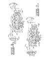
- FIGS. 5 to 7 depict another embodiment of the circuit llb having a modified form of pilot means for controlling shifting of the quick-drop valve between the power-down position and the quick-drop position.
- the pressurized fluid source or pump 24b together with tank 23b, relief valve 28b and main control valve 26b may all be similar to the corresponding components of the previously described embodiment.
- the cylinder 13b including head end and rod end ports 17b and 14b respectively and the load 16b may if desired be similar to the corresponding mechanisms hereinbefore described with reference to the first embodiment.
- a head end flow path conduit 31b containing a flow restriction 47b is connected between main control valve 26b and the head end port 17b of the cylinder and with the second valve port 41b of quick-drop valve housing 32b.
- a rod end flow path conduit 29b is again connected between the main control valve 2Gb and third valve port 44b of quick-drop valve housing 32b while the first valve port 37b again connects to cylinder red end port 14b through a flow line 38b.
- the quick-drop valve housing 32b has a cylindrical valve chamber 33b with three axially spaced-apart grooves 40b, 36b and 45b at which valve ports 41b, 37b and 44b respectively are located.
- Valve spool 34b is disposed in bore 33b for axial movement between a normal position, depicted in Figures 5 and 6, at which the spool abuts the left end of chamber 33b as viewed in the drawing and a quick-drop position depicted in Figure 7 at which the spool abuts the opposite end of the chamber.
- Spool 34b is formed with four lands 71, 72, 73 and 74 which define three axially spaced-apart spool grooves 76, 77 and 78.
- the lands and grooves are located on the spool to cause groove 78 to communicate valve ports 37b and 44b when the spool is at the normal position depicted in Figures 5 and 6 while land 73 blocks both such valve ports from the other valve port 41b.
- the intermediate spool groove 77 communicates valve ports 37b and 41b while land 73 blocks both such ports from valve port 44b .
- a second pilot signal line 63b containing a control orifice 75 communicates spool groove 76 with a region 64b of head end flow conduit 31b located between flow restriction 47b and head end motor port 17b.
- a first pilot signal line 57b communicates the first pilot chamber 55b defined by the left end of valve chamber 33b with a region 58b of head end flow passage conduit 31b which is between restriction 47b and the main control valve 26b.
- chamber 33b constitutes a second pilot chamber 59b and is communicated with spool groove 76 by a passage 79 within the spool.
- a compression spring 62b is situated within pilot chamber 59b to bias spool 34b towards the normal position depicted in Figure 5.
- pilot chamber 55b.in conjunction with spool land 71 and pilot signal line 57b constitute a first pilot means 54b for exerting a force tending to urge the spool 3 1 1b away from the normal position depicted in Figure 5.
- the opposite pilot chamber 59b in conjunction with land 7 1 1, pilot signal line 63b, spool groove 76 and spool passage 79 constitute a second pilot means 56b in which fluid pressure forces, aided by the force of spring 62b, act to urge the valve spool towards the normal position depicted in Figure 5.
- Pressure-responsive valve means 80 are provided for equalizing the fluid pressures in the two pilot chambers 55b and 59b during the power-down mode of operation and for producing an abrupt change of pilot pressures when conditions dictate a shift between the power-down position of valve spool 3 1 1b and the quick-drop position of the spool, the pressure-responsive valve means being a piloted check valve 81 of the pilot-to-close form in this example.
- the check valve 81 has an inlet 82 in one end communicated with first pilot signal line 57b and has an outlet 84 in one side communicated with groove 76 of the quick-drop valve spool 34b.
- Check valve 81 further has an internal spool 86 which may retract from inlet 82 to communicate pilot signal line 57b with outlet 84 in response to fluid pressure at the inlet except when a higher pilot pressure is present in a pilot chamber 87 behind the spool.
- a pilot port 88 at the other end of the check valve 81 communicates pilot chamber 87 with the flow line 38bwhich connects first valve port 41b with the rod end port 14b of cylinder 13b.
- setting of the main control valve 26b at the raise position as depicted in Figure 5 causes pressurized fluid from inlet 25b to be transmitted to rod end port 14b of the cylinder through rod end flow conduit 29b, third valve port 44b. spool groove 78, first valve port 37b and flow line 38b. Simultaneously, fluid being discharged from the cylinder head end port 17b is drained to tank through flow conduit 31b and the main control valve. As a result, cylinder 13b retracts to raise load 16b against gravity.
- the quick-drop valve spool 34b is held in the normal or leftward position at this time in part by the force of spring 62b and in part because the direction of flow through restriction 47b creates a pressure differential at which a higher fluid pressure is transmitted to pilot chamber 59b than is transmitted to the opposite pilot pressure chamber 55b. Piloted check valve 81 remains closed at this time and does not affect the net pilot pressure force on valve spool 34b since the high fluid pressure being transmitted to the rod end of cylinder 13b is also transmitted to the pilot chamber 87 of the check valve.
- the circuit llb shifts either to the power-down mode of operation illustrated in Figure 6 or to the quick-drop mode of operation depicted in Figure 7 depending on the direction of the external load forces on cylinder 13b and also depending on the degree to which the operator has opened the main control valve. If the external forces acting on the cylinder 13b resist cylinder extension, then the circuit llb remains in the power-down mode, regardless of the extent of opening of the main control valve.
- the quick-drop valve spool 34b remains in the normal position at which pressurized fluid is transmitted to the head end port 17b of the cylinder and discharge fluid from the rod end port 14b is transmitted to drain through flow line 38b, valve port 37b, spool groove 78, valve port 44b. rod end flow conduit 29b and the main control valve 26b. If the flow rate through restriction 47b is kept below a particular value the pressure differential between pilot chambers 55b and 59b is not high enough to compress spring 62b since such differential is a function of flow rate through the restriction.
- check valve 8l opens to eliminate any pressure differential between the two pilot chambers 55b and 59b as long as the pressure at the rod end port 14b of the cylinder is less. than that in the first pilot signal line 57b which is the case until such time as a negative pressure appears'at the head end port 17b.
- main control valve 26b must have been opened Into lower to a degree which provides a flow rate through restriction 47b sufficient to cause the fluid pressure acting on spool 34b within pilot chamber 55b to exceed the opposing fluid pressure acting within pilot chamber 55b by an amount sufficient to compress the spring 62b and move the spool to the Figure 7 position.
- spool land 73 completely blocks the discharge path from the rod end port 14b of the cylinder back to drain while diverting all discharge flow from the rod end port to the head end port 17b of the cylinder thereby enabling extremely fast cylinder extension without loss of control or other adverse effects.
- the circuit llb automatically reverts to the power-down mode of operation when resistance to cylinder extension increases or if the operator reduces the flow rate through restriction 47b by adjustment of the main control valve 26b since either occurrence removes one of the two conditions required for the quick-drop mode.
- Resistance to cylinder extension causes a pressure drop at the rod end port 14b accompanied by a pressure rise at head end port 17b which allows pilot valve 81 to open and equalize the fluid pressures in pilot chambers 55b and 59b.
- Spring 62 then restores spool 34 to the power-down position.
- Restoration of spool 34a to the power-down position also occurs if the flow rate through restriction 47b is reduced sufficiently by manipulation of the main control valve 26b since the fluid pressure differential between pilot chambers 55b and 59b, corresponding to the pressure drop across the restriction, then becomes insufficient to maintain the spring62b in a state of compression.
- Spring 62b then shifts spool 34b back to the power-down position depicted in Figure 6.
- cylinder cxtension then continues at a slower rate in the power-down mode until terminated by operation of the main control valve 26b or by bottoming out of the cylinder at the maximum limit of extension.
Landscapes
- Engineering & Computer Science (AREA)
- Mechanical Engineering (AREA)
- General Engineering & Computer Science (AREA)
- Physics & Mathematics (AREA)
- Fluid Mechanics (AREA)
- Chemical & Material Sciences (AREA)
- Analytical Chemistry (AREA)
- Mining & Mineral Resources (AREA)
- Civil Engineering (AREA)
- Structural Engineering (AREA)
- Fluid-Pressure Circuits (AREA)
- Operation Control Of Excavators (AREA)
Applications Claiming Priority (2)
| Application Number | Priority Date | Filing Date | Title |
|---|---|---|---|
| US95677578A | 1978-11-01 | 1978-11-01 | |
| US956775 | 1997-10-21 |
Publications (2)
| Publication Number | Publication Date |
|---|---|
| EP0010699A1 true EP0010699A1 (de) | 1980-05-14 |
| EP0010699B1 EP0010699B1 (de) | 1984-04-18 |
Family
ID=25498684
Family Applications (1)
| Application Number | Title | Priority Date | Filing Date |
|---|---|---|---|
| EP19790104041 Expired EP0010699B1 (de) | 1978-11-01 | 1979-10-19 | Steuerung für Hydraulikmotoren mit schnell ansprechendem Eilgangventil |
Country Status (4)
| Country | Link |
|---|---|
| EP (1) | EP0010699B1 (de) |
| JP (1) | JPS5563003A (de) |
| CA (1) | CA1141266A (de) |
| DE (1) | DE2966924D1 (de) |
Cited By (4)
| Publication number | Priority date | Publication date | Assignee | Title |
|---|---|---|---|---|
| EP0206934A1 (de) * | 1985-06-20 | 1986-12-30 | Sanyokiki Kabushiki Kaisha | Vorrichtung zur wahlweisen Steuerung von mehreren Arten hydraulischer Antriebsvorrichtungen |
| WO1988010342A1 (en) * | 1987-06-26 | 1988-12-29 | Maskin Ab Tube | Constant pressure regulation of grader blades |
| EP0709577A1 (de) * | 1994-10-28 | 1996-05-01 | Kuhn S.A. | Ventil mit vier Verbindungsöffnungen und zwei Stellungen |
| EP3421819A1 (de) * | 2017-06-30 | 2019-01-02 | Nabtesco Corporation | Antikavitations-hydraulikkreislauf |
Citations (5)
| Publication number | Priority date | Publication date | Assignee | Title |
|---|---|---|---|---|
| FR1576772A (de) * | 1967-08-01 | 1969-08-01 | ||
| US3474708A (en) * | 1968-01-17 | 1969-10-28 | Parker Hannifin Corp | Valve assembly for fluid motors and the like |
| US3568707A (en) * | 1968-12-16 | 1971-03-09 | Int Harvester Co | Quick drop valve |
| US3654835A (en) * | 1970-05-25 | 1972-04-11 | Ato Inc | Regeneration valve |
| US3795177A (en) * | 1971-11-04 | 1974-03-05 | Caterpillar Tractor Co | Fluid motor control circuit providing selective fast motion |
-
1979
- 1979-10-17 JP JP13304879A patent/JPS5563003A/ja active Pending
- 1979-10-19 DE DE7979104041T patent/DE2966924D1/de not_active Expired
- 1979-10-19 EP EP19790104041 patent/EP0010699B1/de not_active Expired
- 1979-11-01 CA CA000338957A patent/CA1141266A/en not_active Expired
Patent Citations (5)
| Publication number | Priority date | Publication date | Assignee | Title |
|---|---|---|---|---|
| FR1576772A (de) * | 1967-08-01 | 1969-08-01 | ||
| US3474708A (en) * | 1968-01-17 | 1969-10-28 | Parker Hannifin Corp | Valve assembly for fluid motors and the like |
| US3568707A (en) * | 1968-12-16 | 1971-03-09 | Int Harvester Co | Quick drop valve |
| US3654835A (en) * | 1970-05-25 | 1972-04-11 | Ato Inc | Regeneration valve |
| US3795177A (en) * | 1971-11-04 | 1974-03-05 | Caterpillar Tractor Co | Fluid motor control circuit providing selective fast motion |
Cited By (6)
| Publication number | Priority date | Publication date | Assignee | Title |
|---|---|---|---|---|
| EP0206934A1 (de) * | 1985-06-20 | 1986-12-30 | Sanyokiki Kabushiki Kaisha | Vorrichtung zur wahlweisen Steuerung von mehreren Arten hydraulischer Antriebsvorrichtungen |
| WO1988010342A1 (en) * | 1987-06-26 | 1988-12-29 | Maskin Ab Tube | Constant pressure regulation of grader blades |
| EP0709577A1 (de) * | 1994-10-28 | 1996-05-01 | Kuhn S.A. | Ventil mit vier Verbindungsöffnungen und zwei Stellungen |
| FR2726343A1 (fr) * | 1994-10-28 | 1996-05-03 | Kuhn Sa | Valve a quatre orifices de raccordement et deux positions |
| US5749390A (en) * | 1994-10-28 | 1998-05-12 | Kuhn S.A. | Valve having four connection ports and two positions |
| EP3421819A1 (de) * | 2017-06-30 | 2019-01-02 | Nabtesco Corporation | Antikavitations-hydraulikkreislauf |
Also Published As
| Publication number | Publication date |
|---|---|
| DE2966924D1 (en) | 1984-05-24 |
| CA1141266A (en) | 1983-02-15 |
| JPS5563003A (en) | 1980-05-12 |
| EP0010699B1 (de) | 1984-04-18 |
Similar Documents
| Publication | Publication Date | Title |
|---|---|---|
| US5347811A (en) | Load-sensing active hydraulic control device for multiple actuators | |
| US4531369A (en) | Flushing valve system in closed circuit hydrostatic power transmission | |
| JP3150980B2 (ja) | 圧力補償液圧制御装置 | |
| JP3298623B2 (ja) | 非シャトル圧力補償器付液圧制御バルブ装置 | |
| US4122865A (en) | Load responsive fluid control valve | |
| US4383412A (en) | Multiple pump load sensing system | |
| US3984979A (en) | Load responsive fluid control valves | |
| US3868821A (en) | Automatic pump control system | |
| US3840049A (en) | Compact fluid motor control system with float position | |
| US4520626A (en) | Hydraulic drive system for single rod cylinder | |
| EP1429036B1 (de) | Hydraulische Ventileinrichtung | |
| US3975909A (en) | Engine sensor hydraulic control system | |
| GB1404562A (en) | Hydraulic systems | |
| US3366064A (en) | Control for hydraulic apparatus | |
| EP0608415B1 (de) | Hydraulische schaltung mit druckausgleichventil | |
| US4089168A (en) | Load responsive fluid control valves | |
| EP0010699A1 (de) | Steuerung für Hydraulikmotoren mit schnell ansprechendem Eilgangventil | |
| JP3562657B2 (ja) | 可変容量油圧ポンプの容量制御装置 | |
| EP0359695B1 (de) | Regelung für eine Pumpe mit veränderlicher Verdrängung | |
| US3746040A (en) | Directional control valve | |
| EP0836678B1 (de) | Hydraulisches sicherheitsbremsventil | |
| EP0404956A1 (de) | Zufuhr von öl unter druck für den zylinder einer maschine | |
| US4058140A (en) | Load responsive fluid control valves | |
| US4960035A (en) | Control system for a hydraulic lift driven by a variable displacement pump | |
| KR100594851B1 (ko) | 유압식 브레이크장치 |
Legal Events
| Date | Code | Title | Description |
|---|---|---|---|
| PUAI | Public reference made under article 153(3) epc to a published international application that has entered the european phase |
Free format text: ORIGINAL CODE: 0009012 |
|
| 17P | Request for examination filed | ||
| AK | Designated contracting states |
Designated state(s): BE DE GB |
|
| GRAA | (expected) grant |
Free format text: ORIGINAL CODE: 0009210 |
|
| AK | Designated contracting states |
Designated state(s): BE DE GB |
|
| REF | Corresponds to: |
Ref document number: 2966924 Country of ref document: DE Date of ref document: 19840524 |
|
| PGFP | Annual fee paid to national office [announced via postgrant information from national office to epo] |
Ref country code: DE Payment date: 19840915 Year of fee payment: 6 |
|
| PGFP | Annual fee paid to national office [announced via postgrant information from national office to epo] |
Ref country code: BE Payment date: 19841231 Year of fee payment: 6 |
|
| PLBE | No opposition filed within time limit |
Free format text: ORIGINAL CODE: 0009261 |
|
| STAA | Information on the status of an ep patent application or granted ep patent |
Free format text: STATUS: NO OPPOSITION FILED WITHIN TIME LIMIT |
|
| 26N | No opposition filed | ||
| PG25 | Lapsed in a contracting state [announced via postgrant information from national office to epo] |
Ref country code: BE Effective date: 19851031 |
|
| BERE | Be: lapsed |
Owner name: CATERPILLAR TRACTOR CO. Effective date: 19851031 |
|
| GBPC | Gb: european patent ceased through non-payment of renewal fee | ||
| PG25 | Lapsed in a contracting state [announced via postgrant information from national office to epo] |
Ref country code: DE Effective date: 19860701 |
|
| PG25 | Lapsed in a contracting state [announced via postgrant information from national office to epo] |
Ref country code: GB Effective date: 19881118 |