EP0010775A1 - Méthodes et dispositions pour transformer des signaux vidéo de couleur dans une sous-porteuse de couleur spéciale qui peut être décodée dans un récepteur de télévision en couleur PAL - Google Patents
Méthodes et dispositions pour transformer des signaux vidéo de couleur dans une sous-porteuse de couleur spéciale qui peut être décodée dans un récepteur de télévision en couleur PAL Download PDFInfo
- Publication number
- EP0010775A1 EP0010775A1 EP79104316A EP79104316A EP0010775A1 EP 0010775 A1 EP0010775 A1 EP 0010775A1 EP 79104316 A EP79104316 A EP 79104316A EP 79104316 A EP79104316 A EP 79104316A EP 0010775 A1 EP0010775 A1 EP 0010775A1
- Authority
- EP
- European Patent Office
- Prior art keywords
- color
- signal
- frequency
- reference signal
- subcarrier
- Prior art date
- Legal status (The legal status is an assumption and is not a legal conclusion. Google has not performed a legal analysis and makes no representation as to the accuracy of the status listed.)
- Withdrawn
Links
- 238000000034 method Methods 0.000 title claims abstract description 32
- 230000005540 biological transmission Effects 0.000 claims abstract description 79
- 238000012545 processing Methods 0.000 claims description 36
- 238000003780 insertion Methods 0.000 claims description 14
- 230000037431 insertion Effects 0.000 claims description 14
- 238000006243 chemical reaction Methods 0.000 claims description 12
- 230000005236 sound signal Effects 0.000 claims description 7
- 238000000926 separation method Methods 0.000 claims description 4
- 239000002131 composite material Substances 0.000 claims description 2
- 238000011084 recovery Methods 0.000 claims 1
- 238000012937 correction Methods 0.000 description 12
- 239000000203 mixture Substances 0.000 description 10
- 238000010586 diagram Methods 0.000 description 9
- 230000003111 delayed effect Effects 0.000 description 6
- 238000012986 modification Methods 0.000 description 4
- 230000004048 modification Effects 0.000 description 4
- 239000000969 carrier Substances 0.000 description 3
- 108010076504 Protein Sorting Signals Proteins 0.000 description 2
- 239000003550 marker Substances 0.000 description 2
- 230000002411 adverse Effects 0.000 description 1
- 230000001427 coherent effect Effects 0.000 description 1
- 238000007796 conventional method Methods 0.000 description 1
- 230000001934 delay Effects 0.000 description 1
- 238000001514 detection method Methods 0.000 description 1
- 230000000694 effects Effects 0.000 description 1
- 230000008030 elimination Effects 0.000 description 1
- 238000003379 elimination reaction Methods 0.000 description 1
- 238000001914 filtration Methods 0.000 description 1
- 230000014509 gene expression Effects 0.000 description 1
- 238000007429 general method Methods 0.000 description 1
- 238000012544 monitoring process Methods 0.000 description 1
- 238000005070 sampling Methods 0.000 description 1
- 238000012163 sequencing technique Methods 0.000 description 1
- 230000001360 synchronised effect Effects 0.000 description 1
Images

Classifications
-
- H—ELECTRICITY
- H04—ELECTRIC COMMUNICATION TECHNIQUE
- H04N—PICTORIAL COMMUNICATION, e.g. TELEVISION
- H04N11/00—Colour television systems
- H04N11/06—Transmission systems characterised by the manner in which the individual colour picture signal components are combined
- H04N11/12—Transmission systems characterised by the manner in which the individual colour picture signal components are combined using simultaneous signals only
-
- H—ELECTRICITY
- H04—ELECTRIC COMMUNICATION TECHNIQUE
- H04N—PICTORIAL COMMUNICATION, e.g. TELEVISION
- H04N9/00—Details of colour television systems
- H04N9/79—Processing of colour television signals in connection with recording
- H04N9/7921—Processing of colour television signals in connection with recording for more than one processing mode
- H04N9/7925—Processing of colour television signals in connection with recording for more than one processing mode for more than one standard
-
- H—ELECTRICITY
- H04—ELECTRIC COMMUNICATION TECHNIQUE
- H04N—PICTORIAL COMMUNICATION, e.g. TELEVISION
- H04N9/00—Details of colour television systems
- H04N9/79—Processing of colour television signals in connection with recording
- H04N9/80—Transformation of the television signal for recording, e.g. modulation, frequency changing; Inverse transformation for playback
- H04N9/82—Transformation of the television signal for recording, e.g. modulation, frequency changing; Inverse transformation for playback the individual colour picture signal components being recorded simultaneously only
- H04N9/83—Transformation of the television signal for recording, e.g. modulation, frequency changing; Inverse transformation for playback the individual colour picture signal components being recorded simultaneously only the recorded chrominance signal occupying a frequency band under the frequency band of the recorded brightness signal
Definitions
- the invention relates to methods for converting a color television signal with a quadrature color carrier into an input signal compatible with PAL color television receivers, the quadrature color carrier having the frequency f c and comprising two signal components amplitude-modulated by a first and a second color difference signal, which are also quadrature-modulated with respect to one another the process steps converting the quadrature color carrier into a special color subcarrier with a frequency that is compatible with a PAL color television receiver and that has a fixed phase angle X, which can be anywhere between 0 0 and 360 0 , but not 0 0 , 90 °, Can be 180 ° and 270 °.
- Such color television signals are generally PAL or NTSC - standard color television signals in Europe or America.
- Magnetic tape recorders therefore usually include means for converting the broadcast format into a suitable transmission channel format and for converting the signals back into a broadcast format so that the recorded information can be reproduced in an ordinary television receiver.
- the present invention is primarily concerned with such devices for use in cases where the signal originally received (to be recorded) is either an NTSC or PAL format owns and the receiver used to reproduce the recorded signals is a PAL receiver.
- both color television signals in the NTSC format and those in the PAL format comprise a baseband luminance signal, an audio signal carrier and a quadrature-modulated color carrier.
- the color carrier contains a component with phase angle + 33 °, which is modulated with a first color signal Q, and a quadrature component with phase angle + 123 °, which is modulated with a second color signal I.
- the signals Q and I are obtained from color difference signals BY and RY, where B represents the color blue and R represents the color red and Y represents a luminance signal according to the following equations:
- the color carrier in PAL format comprises a component with a phase angle of 0 °, which is modulated with a color difference signal U, the latter being 0.493 (BY), and a quadrature component with a phase angle that changes in successive scan lines between + 90 ° and -90 ° .
- Color burst signals which serve as phase and frequency references for the quadrature color signal components, are present during the horizontal blanking intervals.
- NTSC bursts have a phase angle of 180 °
- PAL bursts alternate between the phase angles +135 0 and -135 0 in successive lines.
- U.S. Patent 4,123,374 discloses a number of color television 'signal encoders which employ general methods of the type described above to process NSTC or PAL signals. These known devices comprise a recording subsystem by means of which a television input signal for a transmission channel, e.g. Magnetic tape, is converted into a special transmission channel format, and a reproduction subsystem for converting back the signal recovered from the transmission channel into approximately its original format.
- a transmission channel e.g. Magnetic tape
- This special transmission channel signal format for the television signal input into the transmission channel is the same for all known devices and comprises frequency-modulated luminance and audio signal carriers as well as a bisequential, frequency-reduced color subcarrier which is amplitude-modulated on alternating lines with suppressed carrier frequency, first with the color difference signal U and then with the color difference signal V (or 0.877 (RY)).
- the quadrature color carrier for reproduction is generated again in that the AM-modulated bisequential color subcarrier is frequency-converted and the phase angles are switched sequentially in order to restore the quadrature modulation, so that two consecutive color carrier components with a line spacing are obtained.
- the original NTSC quadrature color support is recovered.
- PAL signals When PAL signals are reproduced, in principle the same back conversion of the color subcarrier is carried out, with an inverter / switch combination sequentially sequencing the quadrature color carrier in the PAL sense between the phase +90 0 and -90 0 r switches.
- the color burst signals are generated as usual for 1 NTSC or PAL and used in the line blanking bridges of the restored quadrature color carriers.
- a first disadvantage of the known devices for processing PAL color television signals discussed above arises from the fact that a delay line is necessary in order to recover the quadrature-modulated color carrier. Such delay lines complicate and make the devices more expensive.
- the use of a delay line results in mis-registration of the luminance and chrominance information in the picture reproduced by a conventional PAL color television receiver. This is because half of the color information is always delayed by one line period, while the luminance information is not delayed at all.
- a second disadvantage of the known devices for converting PAL signals or NTSC signals is that the maximum amplitude of the modulated color signal varies depending on whether the color carrier is modulated with the difference signal V or U.
- V has an amplitude that is 3 dB greater than that of U.
- the differential signal U has a dynamic that cannot be used, and a correspondingly lower signal-to-noise ratio is the result of the lower signal amplitude.
- a third disadvantage of the known devices in which PAL signals are processed results from the fact that true color bursts in quadrature-modulated color carrier signals can only be generated by adding separated bursts which occur in successive line blanking intervals of the bisequently modulated color subcarrier. A burst of correct phase is therefore only generated with the second line of color information of each field.
- the color quality in a video image which is supplied with the aid of the color reproduction of a conventional PAL television receiver to which such a conversion device is connected, can therefore be adversely affected.
- the television receiver input signal generated as a special color subcarrier signal contains an intermediate color subcarrier of frequency f with a fixed phase angle X.
- the special color subcarrier without the use of a delay line, can be used to delay a signal by the duration of one line and can be decoded in a conventional PAL receiver as if it were a conventional PAL receiver input signal.
- This special color subcarrier signal can be generated via amplitude modulation of a reference signal with the frequency f c and with a fixed phase angle X, with a baseband signal which alternately K (U sin (X) + V cos (X)) and K (U sin (X) ) - V cos (X)) is proportional.
- the baseband signal can be produced by demodulating the quadrature color carrier with the aid of a reference signal of the same frequency, which has a fixed phase angle at + K (90 ° -X).
- the baseband signal can be produced by demodulating the quadrature color carrier with a coherent reference signal whose phase angle is switched between + K (90 ° -X) and -K (90 ° -X) in alternating lines.
- the angle X is preferably + 45 °.
- the arrangement according to the invention comprises a recording part for receiving color television signals in PAL format and for converting them into the intermediate color subcarrier for the transmission channel.
- the arrangement further comprises a reproduction part for receiving the encrypted signal recovered from the transmission channel and converting it into the special color subcarrier signal, which is suitable for correct reception and decoding by a conventional PAL receiver.
- the recording part comprises receiving means for the PAL signal and means for separating the quadrature color carrier from baseband luminance signal and from the audio carrier signal, and demodulator means for reducing the Color subcarrier on a baseband color signal.
- This baseband color signal is an alternating signal sequence which includes U + V in one line and U - V in the next line. It is generated by mixing the color subcarrier with a reference signal, the frequency of the latter being the same as that of the color carrier (namely f c ) and the phase angle being fixed at 45 ° relative to the reference phase defined by the color bursts of the PAl signal.
- the arrangement of this embodiment further comprises AM modulator devices for the intermediate color subcarrier with the baseband color signal and for its summation to the frequency-modulated luminance and audio carrier signals.
- the carrier frequency f t is suppressed.
- the intermediate color subcarrier is printed on alternating lines with U + V 'respectively. U - V modulated.
- the maximum amplitude of the carrier signal modulated with U + V is only about 0.5 db larger than the maximum amplitude in the case of modulation with U + V. It is therefore possible to utilize the full dynamic range for the color signal reproduction and the signal-to-noise ratio during each scanning line is approximately the same size for each line.
- the reproducing part comprises receiving devices for the television signal recovered from the transmission channel and for further separation of the modulated color subcarrier from the brightness and audio carrier signals, and demodulator devices for reducing the separated color subcarrier to a baseband color signal which corresponds to that in the recording part of the arrangement generated signal is identical.
- the playback section also includes modulator means for converting the baseband signal into a modulated carrier signal of frequency f and a fixed phase angle of + 45 °.
- modulator means for converting the baseband signal into a modulated carrier signal of frequency f and a fixed phase angle of + 45 °.
- the reproducing part according to this embodiment of the invention also comprises summing devices for PAL color burst signals to the modulated color subcarrier, as well as devices for adding the resulting signal with baseband luminance and audio carrier signals so as to generate a special television signal, the special format of which it is used for Modulation of a carrier as well as for correct reception and decoding by a conventional PAL television receiver.
- the intermediate steps of reducing the quadrature color carrier and the intermediate color subcarrier in the transmission channel are eliminated in the baseband frequency position.
- the recording part comprises means for directly converting the quadrature color carrier into the intermediate color subcarrier of the transmission channel
- the reproducing part contains means for directly converting the intermediate color subcarrier into the special color subcarrier signal.
- this is achieved by means of mixing the modulated color subcarrier with a third reference signal, which is produced by mixing a first reference signal of frequency f t with a second reference signal of frequency f and which has a phase of +45 0 .
- This third reference signal contains sum and difference frequencies of f c and f t .
- the alternative embodiment is the same as the first described embodiment.
- the recording part of both embodiments provides coded signals which have the same transmission channel format, it is understood that the recording part of one arrangement can be combined with the reproducing part of the other arrangement.
- the recording part is essentially the same as in the first arrangement for PAL signals mentioned above.
- the phase of the reference signal supplied to the demodulator devices does not have a fixed phase angle of + 45 °, but is switched sequentially between the angles + 45 ° and -45 0 .
- the demodulator devices generate a baseband color signal which contains an alternating signal sequence which is proportional in one horizontal line of the sum of the color difference signals, ie U + V, and in the next line of the difference, ie U - V. This is the same baseband color signal that is generated in the embodiment of the arrangement described above.
- the recording part is essentially the same as described above.
- a third reference signal supplied to the mixing devices is obtained by mixing a first reference signal of frequency f t with a second reference signal of frequency f c , this second signal on alternating lines between the phase angles + 45 ° and - 45 ° is switched. This creates a modulated intermediate color subcarrier for the transmission channel, which is identical to the versions described above.
- the appearance of cross-modulation between color and brightness signals can essentially This prevents f t , i.e. the frequency of the intermediate color subcarrier in the transmission channel, from being chosen an odd multiple of a quarter of the line frequency or as an odd multiple of half the line frequency, where in the latter case the phase angle of the color subcarrier is switched in alternating line pairs .
- Second generating means for a second reference signal of frequency f t with a phase which changes its sign in successive pairs of scan lines, the frequency f t being an odd multiple of half the line frequency; a second double balanced modulator for mixing the baseband color signal with the second reference signal to produce the intermediate color subcarrier; Means whereby a second double symmetric modulator can be made unbalanced during the duration of the line blanking gaps so that color bursts are generated during these gaps and these color bursts have a frequency and a phase which correspond to the second reference signal and facilitate the later correction of time base errors in the color television signal of the transmission channel format ; a second filter for removing unwanted modulation components from the intermediate color subcarrier, which is generated by the double-symmetric modulator; Separating means for the baseband brightness signal from the rest of the PAL color television signal and for converting the separated brightness signal into a frequency-modulated brightness carrier signal; and a summing device for the filtered intermediate color subcarrier with the frequency-modulated brightness and audio carrier signal for
- An arrangement for converting a conventional PAL color television signal which comprises a baseband brightness signal, a frequency-modulated audio carrier signal and a quadrature color carrier of a frequency f, amplitude-modulated with color difference signals U and V, into a special transmission channel signal format, the frequency-modulated audio and brightness carrier signals and an intermediate color subcarrier, amplitude modulated with a frequency f t and in successive scan lines alternately with U + V or U - V, is given by s first filter means for separating the quadrature 'color subcarrier from the rest of the PAL color television signal; first signal generating means for determining the color bursts in the line blanking intervals of the separated quadrature color carrier and for generating a first reference signal with the frequency f c and a fixed phase which is a multiple of 45 °, sampling devices for inserting color bursts which differ over the Extend the duration of the line blanking intervals and their frequency and phase correspond to those of the first reference signal, so that a later
- An arrangement for converting an NTSC color television signal which comprises a baseband brightness signal, a frequency-modulated audio carrier signal and a quadrature color carrier, the frequency of which is f c and which is amplitude-modulated with the color difference signals I and Q, into a special signal format which contains frequency-modulated audio and brightness carrier signals and an intermediate color subcarrier of frequency f t and which is amplitude-modulated alternately with U + V or U - V in successive scan lines, the relationship between U and V on the one hand and I and Q on the other hand being represented by the following equation becomes: is characterized by first separation filters for separating the quadrature color carrier from the rest of the NTSC color television signal; first means for determining the color bursts in the line blanking intervals of the separated quadrature color carrier and for generating a first reference signal with the frequency f and a phase which alternates between + X and -X in alternating scanning lines, where X is an odd multiple of +45 Is 0 and these first means
- the invention can be implemented with an arrangement which has a recording part for receiving a color television signal in PAL or NTSC format and converts this into a transmission channel signal format for transmission over a transmission channel, e.g. Recording on magnetic tape, which also has a playback section for receiving the encoded signal which has been recovered from the tape and for converting it into a special color subcarrier signal with a PAL-compatible signal format for processing according to conventional methods and for input into a conventional PAL television receiver.
- a recording part for receiving a color television signal in PAL or NTSC format and converts this into a transmission channel signal format for transmission over a transmission channel, e.g. Recording on magnetic tape, which also has a playback section for receiving the encoded signal which has been recovered from the tape and for converting it into a special color subcarrier signal with a PAL-compatible signal format for processing according to conventional methods and for input into a conventional PAL television receiver.
- both NTSC and PAL color television signals contain a baseband luminance signal, an audio carrier signal and a quadrature color carrier.
- the NTSC color carrier comprises a component with a phase angle of 33 °, modulated with a color difference signal Q (ie 0.41 (BY) + 0.48 (RY)), and a quadrature component with a phase angle of 123 °, modulated with a color difference signal I (ie -0.27 (BY) + 0.74 (RY)).
- Color bursts with a phase angle of 180 ° appear during the horizontal blanking gaps.
- the PAL color carrier comprises, on the one hand, a component with a phase angle of 0 0 , modulated by U (or 0.493 (BY)) and a quadrature component with a phase angle, which switches between +90 0 and -90 ° on alternating lines and is modulated by V (or 0.877 (RY)).
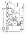
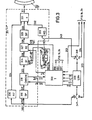
- FIG. 1 a shows, in conjunction with FIG. 1 b, an embodiment of the invention in which a PAL color television signal is received on line 110 and encoded by a recording part 111 (FIG. 1 a) for storage on a magnetic tape 112.
- a playback part 113 receives the coded signal recovered from the tape and places it in the PAL-compatible special color subcarrier signal for output on line 114.
- the recording section 111 comprises a bandpass filter (BP) 116 for receiving the color television signal arriving on line 110 (PAL) and for separating the quadrature modulated color carrier from the baseband luminance and audio carrier signals.
- BP bandpass filter
- the separated ink carrier is sent via line 117 to a color signal processing device (CHROM) 118 which is controlled by a conventional burst marking signal (BF) which comes on line 119 from a time circuit (T) 120 and which is a conventional PAL identification signal ( PAL ID) and a reference signal of frequency f with a phase of 0 ° (ie, f c ⁇ 0 °).
- the color signal processing device 118 may be a commercially available linear integrated circuit.
- the PAL identification signal and the reference signal F c ⁇ 0 o are fed via lines 121 and 122, respectively, to the timing circuit 120, which in turn supplies all the timing signals required for the correct operation of the recording and reproducing parts of the arrangement.
- the color signal processing device 118 also provides at its output a color subcarrier, which is prepared for transmission via line 123 to one of the inputs of a first double-symmetric modulator (D1) 124, the latter demodulating the subcarrier to the baseband.
- the baseband color signal thus obtained is then transmitted via line 126 to one of the inputs of a second double-balanced trical modulator (D2) 127, which generates a modulated intermediate color subcarrier of frequency f t , for transmission via line 128 to a bandpass filter 129.
- a double balanced modulator is a known circuit which multiplies the signals applied to its two inputs to produce an output signal with components whose frequencies represent both the sum and the difference of the frequencies of the corresponding input signals.
- Such a modulator circuit is preferred in this arrangement because the output signal generated by it has no interference from the corresponding input signals. As a result, modulation with suppressed carrier frequency is achieved automatically.
- Both modulators 124 and 127 can be commercially available double-symmetrical modulator-demodulator elements in the form of integrated circuits.
- the band filter (DP) 129 eliminates all undesired modulation components, in particular also those which arise in the addition frequency component generated by the first double-symmetric modulator (D1) 124.
- the filtered subcarrier is then fed via line 130 to a summing amplifier 131 which adds it to the frequency modulated luminance and audio carrier signals to produce an encoded composite television signal which can be recorded on magnetic tape (TP) 112 in a known manner.
- the summing amplifier 131 receives the frequency-modulated luminance carrier signal via line 132 from a luminance modulator 133 and the frequency-modulated audio carrier signal via line 134 from an audio frequency processing circuit (AU) 136.
- AU audio frequency processing circuit
- the carrier frequencies and band- L J widths of the luminance and audio carrier signals selected such that interference with the modulated color subcarrier is avoided. Examples of a suitable luminance modulator and a suitable audio signal processing circuit for generating these carrier signals are also described in the US patent.
- the intermediate color subcarrier of the transmission channel is alternately modulated with U + V in one line and with U - V in the next line: in the arrangement in FIG. 1a, this is done by corresponding first and second reference signals, namely f c ⁇ +45 ° and f t ⁇ 0 ° via lines 137 and 138 to the corresponding second inputs of the first and second double-symmetric modulator (D1 and D2) 124 and 127.
- the first reference signal f c ⁇ + 45 ° which is applied to the first modulator 124 via the line 137, has a frequency f c and a phase set to + 45 ° (relative to the reference signal defined in the color signal processing part (CHROM) 118) f c ⁇ 0 °).
- the phase between this reference signal f c ⁇ 45 ° and the color component U is always 45, and the phase between the reference signal and the color component V alternately 45 ° in one line and 135 ° in the next.
- the baseband color signal (on line 126) (ie, the differential frequency component) generated by the first modulator (D1) 124 is alternately proportional to U + V in one line and U - V in the next.
- the sum frequency 2f c can be neglected since its effects are later eliminated by the band filter (BP) 129.
- the reference signal f t ⁇ 0 ° which is fed via line 138 to the second double-symmetric modulator 127, has a frequency f t which is an odd multiple of one Quarter of the line frequency, and a relative fixed phase of 0 °.
- the reference signals fed to the two double-symmetrical modulators (D1 and D2) 124 and 127 are generated by the time circuit (T) 120.
- the luminance processing circuit (LUM) 139 receives and processes the television input signal in PAL format to produce the conventional burst marker signal (BF), which contains a series of pulses that coincide with the color burst signals (BS). coincide, a conventional blanking signal (BK) which contains a series of pulses which extend over the duration of a horizontal blanking or line blanking interval and also a vertical blanking signal (VBK).
- BF conventional burst marker signal
- BK conventional blanking signal
- VBK vertical blanking signal
- the luminance processing circuit (LUM) is 139, the baseband brightness or luminance of the color and audio carrier signals separated and do about LEI g 143 supplied to the Luminanzmodulator 133, where it is frequency modulated prior to its recording on magnetic tape 112th
- the luminance processing circuit (LUM) 139 can comprise a known synchronization signal generator, for example in the form of an integrated circuit.
- the timing circuit 120 generates the reference signal f c ⁇ + 45 ° by delaying the color reference signal f c ⁇ 0 °, which is supplied via line 122 from the color signal processing part (CHROM) 118, and generates the reference signal f t ⁇ 0 ° by latching it Frequency with an odd multiple of a quarter of the line frequency (determined by blanking signal BK supplied by line 141 from luminance processing circuit (LUM) 139). A suitable device for generating the reference signal f t ⁇ 0 ° is known.
- the timing circuit 120 also provides a clock signal over line 144 to the luminance processing circuit (LUM) 139 to control its operation.
- the luminance processing circuit (LUM) 139 has first and second manually operable switches 145 and 148, respectively, which are provided at the television signal input and its baseband luminance signal output, respectively. With the help of these switches, the circuit (LUM) 139 can be used both during the recording of a television signal on tape (TP) 112 and during the playback of the signal recovered from the tape.
- record mode (“R"), the input for the PAL television signal is connected to the processing circuit (LUM) 139 and the baseband luminance signal generated by the circuit is supplied to the luminance modulator 133 for FM modulation.
- the recording part comprises insertion devices for inserting color burst signals (BS) into the modulated intermediate color subcarrier for the duration of all successive line blanking intervals (BL ) with the exception of a few.
- BS color burst signals
- BL line blanking intervals
- this is indicated by an i Burst control signal reached which is applied on line 147 from timing circuit 120 to a gain adjustment terminal of the second double balanced modulator (D2) 127 to unbalance the modulator during such intervals.
- the modulator (D2) 127 consequently generates an unmodulated output signal during these periods which corresponds to the reference signal f t ⁇ 0 °.
- the color burst signals (BS) in the selected lines are suppressed to indicate which lines correspond to the U + V color information and which correspond to the U - V color information.
- the color burst is suppressed in every fourth line during the vertical blanking interval in order to indicate that these lines (as well as other lines synchronized with them) contain the color information U + V. Since each video picture contains an odd number of lines, the line changes or the lines in which the color burst signals are suppressed change from one picture to the next.
- Timing circuit (T) 120 accomplishes this row selection by combining the vertical blanking signal (BK) received on line 142, the PAL identification signal (PAL ID) received on line 121, and the output of a flip-flop (not shown) which is from the PAL ID signal is clocked.
- the burst control signal can then be generated by combining the inverted line selection signal with the blanking signal mixture (BK).
- the television signal mixture generated by the recording part 111 for recording on magnetic tape (TP) 112 comprises frequency-modulated luminance and audio carrier signals, as well as an AM-modulated color subcarrier, which is modulated on sequential lines with U + V and U - V , the carrier frequency suppressing L J and with unmodulated color bursts that occur for the duration of all successive horizontal blanking gaps, with the exception of a few.
- the maximum amplitude of the modulated color signal is approximately the same for all lines, so that almost the full dynamic range of the color reproduction in each line can be used and the signal-to-noise ratio in each line is approximately the same.
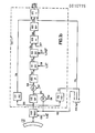
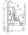
- the playback part 113 in Figure 1b cooperates with the timing circuit (T) 120 and the luminance signal processing circuit (LUM) 139 of Figure 1a to convert the television signal mixture recovered from the magnetic tape (TP) 112 into the special one, for modulating a carrier signal and for receiving and converting the decoding by a conventional PAL television receiver suitable output format (special - color subcarrier signal).
- the tape-recovered television signal is processed in a time base corrector (TBEC) 148 to compensate for the fluctuations in time during the recording and playback of the signal.
- TBEC time base corrector
- the error correction device (TBEC) 148 causes a variable delay of the television signal to adjust the phase of the color bursts in the tape-recovered television signal to that of the reference signal f t LQ °, which is supplied via line 138 from the time circuit (T) 120.
- T time circuit
- the receiver part 113 comprises a bandpass filter (BP) 149, which receives the television signal mixture supplied on line 150 from the time base correction device (TBEC) 148 and the AM-modulated intermediate color subcarrier from the FM-modulated brightness and Separates sound carrier signals.
- the severed Intermediate color subcarrier is fed via line 151 to a 'first gate 152, which separates the color bursts (BS) which occur during the line blanking intervals for retransmission via line 153 to the time base correction device (TBEC) 148, and a second gate 154, via which the color bursts are eliminated to just leave the modulated intermediate color subcarrier.
- the blanking signal BK and the inverted signal BK are fed from the time circuit (T) 120 via the lines 156 and 157 to the gates 152 and 154, respectively, in order to control their separation function.
- the modulated intermediate color subcarrier is fed from the second gate 154 via line 158 to a phase equalizer (0) 159, which corrects undesired phase changes caused by the signal being filtered out both in the bandpass filter (BP) 129 of the recording part 111 and in the bandpass filter (BP). 144 of the reproducing part 113 occur.
- the phase-equalized intermediate color subcarrier is connected via line 160 to an input of a first double-symmetric modulator 161, which demodulates it to a baseband signal which corresponds to the baseband color signal generated in the recording part in FIG. 1a.
- a second input of the modulator (D1) 161 is supplied with the reference signal f t ⁇ 0 °, which is transmitted on the line 138 by the timing circuit 120.
- the phase of the intermediate color carrier supplied to the modulator (D1) 161 is automatically adjusted to that of the reference signal by means of the time base correction device 148.
- the baseband color signal generated by the first double-symmetric modulator (D1) 161 is then fed via line 162 to an input of a second double-symmetric modulator (D2) 163, which has an output color subcarrier f c ⁇ + 45 ° (special color subcarrier signal) with under-L J pressed carrier, the carrier frequency is fed to a second input of the modulator (D2) 163.
- the subcarrier frequency f c ⁇ + 45 ° is supplied via line 137 from the time circuit (T) 120 and can originate from an oscillator (not shown here) which cooperates with the color signal processing circuit (CHROM) 118.
- the oscillator operates "feedback-free" when the device is processing a signal recovered from the tape (TP) 112 and no television signal is being received by the color processor (CHROM) 118.
- the special color subcarrier signal modulated by the second double-symmetrical modulator (D2) 163 is fed via line 164 to a summing device 166, in which it contains the conventional color bursts in PAL format (ie + 135 ° and -135 0 on alternating lines), which via the Line 167 received by the time circuit (T) 120, summed.
- the +135 color bursts are generated in lines, the U - V color information and the -135 0 bursts in those lines which contain the U + V color information.
- Corresponding synchronization of the burst phase with that of the color signal can be achieved by means of the timing circuit (T) 120 by monitoring the controlled transmission channel color bursts supplied by line 152 from gate 152 in order to prevent the absence of burst signals during the few scanning lines falling into the vertical blanking interval discover. It is recalled that lines without color bursts contain U + V color information. As soon as it is established that a certain line has a color burst, a flip-flop (not shown here) which is clocked by the periodically occurring burst marking signal BF is reset. The flip-flop is therefore in the "one" state for lines which contain U + V color information and in the "zero" state for lines which contain UV color information.
- the output of the flip-flop is used alternately 'To select phase reference signals between + 135 ° and -135 0 , both of which are generated by a corresponding delay in the reference angle + 45 ° (ie f c ⁇ 45 °), the PAL bursts to be supplied on line 167 then being clocked by the selected one Phase reference signal can be obtained with the burst marking signal BF.
- the color subcarrier generated by the summing device 166 is fed via line 168 to a bandpass filter (BP) 169 for the purpose of eliminating the undesired modulation components and then via line 170 to a summing amplifier 171 for addition with a baseband luminance signal and a frequency-modulated audio carrier signal.
- BP bandpass filter
- the baseband luminance signal which is supplied to the summing amplifier 171 is originally generated by a brightness modulator 172 which is contained in the reproduction part 113 for demodulating the FM-modulated luminance carrier signal in the television signal received by the time base error correction device (TBEC) 148. If the manually operated switches 145 and 146, which are assigned to the luminance processing circuit (LUM) 139 (FIG. 1a), are switched to the playback state ("P"), then the baseband produced by the luminance demulator 172 is switched off. Luminance signal via line 173 to the circuit (LUM 139).
- the luminance processor (LUM) 139 Since it was in the operating state when the device was in record mode ("R"), the luminance processor (LUM) 139 processes the television signal to generate a burst marker signal (BF), the blanking signal mix (BK) and the vertical blanking signal To deliver transmission over lines 140, 141 and 142 to time circuit (T). In addition, the circuit (LUM) 139 outputs the baseband luminance signal for transmission via the second switch 146 and via line 174 to the summing amplifier 171. L
- the audio carrier signal which is fed to the summing amplifier 171 via line 176 from the audio processing circuit 177 has the carrier frequency of an original PAL television signal which is received by the recording part 111 (FIG. 1a).
- the display part 113 shown in FIG. 1b provides, according to the invention, a special television signal with a PAL-compatible signal format, which comprises a baseband luminance signal, and an FM-modulated audio carrier signal and a special color subcarrier signal which is amplitude-modulated - line sequential with suppressed subcarrier - with U + V in one scan line and with U - V in the next.
- color bursts with correct phase angles ie +135 0 and -135 ° * in successive lines
- Both luminance and audio signals are identical to the original luminance and audio signals contained in the PAL television signal received by the recording system 111.
- the special color subcarrier is very different from the quadrature color subcarrier of the original television signal. Nonetheless, the special format signal can be properly decoded by a conventional PAL television receiver, just as if it had a conventional PAL signal format, and can be generated without an expensive delay line.
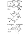
- FIG. 5 shows the color demodulator part of a conventional PAL television receiver which is used to demodulate the color subcarrier and to reproduce the two baseband color difference signals U and V.
- the demodulator receives the color subcarrier input on line 178 and delays it via delay line 179 for one scan line. Farther "the demodulator receives a pair of demodulation channels for the U or V signal.
- the U demodulation channel includes a summer 180 to sum the color subcarrier signal received on line 178 with the delayed subcarrier provided on line 181 by delay line 179.
- the output of the summing element is transmitted via line 182 to a U-demodulator circuit 183 for mixing with a reference signal f c ⁇ 0 °, which is received via line 184.
- the V-demodulation channel contains a subtracting device 185, from which the delayed subcarrier is subtracted from the subcarrier input and the difference signal thus obtained is applied via line 186 to a V-demodulation circuit 187 for mixing with a reference signal f c ⁇ + 90 °, ⁇ -90 °, which is fed on line 188.
- the color demodulator shown in FIG. 5 demodulates a conventional PAL color carrier, which comprises the quadrature color carrier components, the first with the phase angle 0 °, which is modulated with U, and the second with the phase angle, which is sequential between +90 0 and -90 changes and is modulated with V.
- the summing element 180 which sums the carrier signals of successive lines, generates a signal with a phase angle of 0 ° and modulated with 2 U, since the components modulated with V essentially cancel each other out.
- the subtractor 185 which subtracts the carrier signals of successive lines from one another, generates a signal with a phase angle that changes between + 90 ° and -90 ° and is modulated with 2 V, since the components modulated with U essentially cancel each other out .
- the baseband color difference signal U is produced for output on line 189.
- the baseband is formed Color difference signal V for output on line 190.
- the conventional color demodulator of Figure 5 is also able to demodulate the PAL-compatible special color subcarrier signal which is generated with the arrangement according to the invention in order to obtain the baseband color difference signals U and V.
- the special color subcarrier is advantageously a line-sequential signal with the phase angle +45 0 , which is modulated alternately with U + V in one line and with U - V in the next line.
- the summing device 180 When this special color subcarrier signal is demodulated, the summing device 180 generates a signal with a phase angle +45 0 and modulates with +2 U, which in turn is demodulated by the U demodulator 183 to form the baseband color difference signal U. Similarly, the subtraction device 185 generates a signal with a phase angle of + 45 ° and modulated alternately with +2 V or -2 V, which in turn is demodulated in the V demodulator 187 to give the other color difference signal V.
- means 180 Upon demodulating this general signal format color subcarrier, means 180 continuously sums the current scan line subcarrier and the previous line subcarrier to produce a phase X signal modulated with (2K sin (X)) U.
- This signal is in turn fed on line 182 to U-demodulator 183, where it is mixed with the reference signal f c ⁇ 0 ° arriving on line 184.
- the phase difference between these two signals is the angle X.
- the U demodulator 183 thus generates a baseband signal (2 K sin (X) cos x)) U, the factor 2 K sin (X) cos (X) for all X- Values is positive.
- the device 185 continuously subtracts the subcarrier of the previous scan line from the subcarrier of the current line to form a signal with the phase angle X, which on alternating lines with + (2 K cos (X) V and - (2 K cos (X) V.
- This signal is again fed on line 186 to V demodulator 187 where it is mixed with the reference signal f c ⁇ 90 °, ⁇ -90 ° arriving on line 188.
- the phase difference between the two signals alternates between the angles (X-90 °) and (X - (- 90 °)).
- the V-demodulator 187 thus generates a baseband signal which alternately expresses + (2 K cos (X) cos (X-90 °)) V and - (2 K cos (X) cos (X - (- 90 °))) V. Both expressions are equivalent to + (2 K cos (X) sin (X)) V, with the factor 2 K cos (X) are (X) positive for all X values and are identical to the factor at the output of the U-Demodula- tors 183 appears.
- the nominal gain of the two U and V demodulator channels therefore has the same value, and the PAL demodulator demodulates the color subcarrier according to the invention with a general signal format just as correctly as if it were a conventional PAL quadrature color carrier.
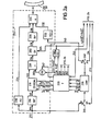
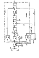
- FIGS. 2a and 2b show a further arrangement of the invention, which comprises a recording part 211 (FIG. 2a) for converting the PAL color television signal into the transmission channel format for storage on magnetic tape 212 and a reproducing part 213 (FIG. 2b) for converting what has been recovered from the tape Signals included in a PAL-compatible special signal, which is suitable for modulating a carrier and for receiving and decoding by a conventional PAL television receiver.
- a recording part 211 for converting the PAL color television signal into the transmission channel format for storage on magnetic tape 212
- a reproducing part 213 FIG. 2b
- each reference number used to identify a unit in Figures 2a and 2b are the same as the last two digits used to identify the corresponding units in Figures 1a and 1b. The same applies to the reference numbers for identifying corresponding units in FIGS. 3 and 4. Otherwise, the highest digit of each reference number corresponds to the number in the drawing in which it appears.
- the recording part 211 in Figure 2a is substantially similar to the recording part 111 in Figure 1a.
- the color television signal in PAL format arrives on line 210 and the quadrature color carrier is separated from the brightness and audio signals via a bandpass filter (BP) 216.
- BP bandpass filter
- the separated color subcarrier is then processed in a color signal processor (CHROM) 218 to produce a PAL identification signal (PAL ID) and a color phase detector.
- CHROM color signal processor
- PAL ID PAL identification signal
- T time circuit
- Color bursts that occur during all successive line blanking gaps - with the exception of a few - are inserted here in a different way than in the arrangement in FIG. 1a.
- the color bursts are combined with the processed quadrature color carrier in a summing device 219 which is connected downstream of the color signal processing device (CHROM) 218.
- CHROM color signal processing device
- these color bursts facilitate the detection and correction of time base errors which occur as a result of the steps of recording and reproducing the transmission signal on tape.
- the color bursts supplied to the summing device 291 are generated by a gate 292 which inserts a reference signal f c ⁇ + 45 ° in accordance with a burst control signal, these signals being provided on lines 237 and 247 by the timing circuit (T) 220.
- the summer 291 receives the color bursts on line 292a from the gate 292 and the converted color carrier on line 223 from the color signal processing circuit (CHROM) 218.
- the quadrature color carrier with the extended color bursts is then converted in a double-symmetrical modulator (D1) 293 into the modulated intermediate color subcarrier, sieved in a bandpass filter (BP) 229 to remove undesired modulation components, and then in a summing amplifier 231 with FM modulated brightness and audio carrier signals to be combined.
- D1 double-symmetrical modulator
- BP bandpass filter
- summing amplifier 231 with FM modulated brightness and audio carrier signals to be combined.
- FIGS. 1a and 2a The main difference between the explanations of FIGS. 1a and 2a can be seen in the method for converting the quadrature color carrier of frequency f c into the modulated intermediate color subcarrier of frequency f t .
- the intermediate step of reducing the quadrature color carrier to the base band is omitted, and this color carrier is instead implemented directly in the modulated intermediate color subcarrier.
- the direct conversion of the color carrier takes place in the double-symmetrical modulator (D1) 293 in such a way that the quadrature color carrier supplied on line 294 by the summing device 291 is fed to one of its inputs and that a second input receives a special reference signal via line 295, this reference signal components with the sum and difference frequencies of f and f t which are denoted by f c ⁇ + 45 ° + f t ⁇ 0 °.
- the special reference signal is obtained by mixing the reference signal f c ⁇ + 45 ° with another reference signal f t ⁇ 0 ° in a second double-symmetric modulator (D2) 295a.
- the reference variables f c ⁇ + 45 ° and f t ⁇ 0 ° are both generated by the time circuit (T) 220 and applied to the first and second inputs of the modulator (D2) 295a via lines 237 and 238, respectively.
- the frequency of the signal f t ⁇ 0 ° is chosen as an odd multiple of a quarter of the line frequency, causing the visible disturbance of the reproduced video image, which is due to the cross modulation of the color subcarrier and the frequency-modulated brightness carrier signal rests, is reduced. Otherwise, the frequency f t can be chosen as an odd multiple of half the line frequency and the phase on sequential line pairs change their sign.
- the double symmetrical modulator (D1) 293 generates an output signal with components that contain sum and difference frequencies of the input signals. Such a component is an intermediate color subcarrier f t ⁇ 0 ° with frequency f t ) which is sequential with U + V or This component of the output signal is the only one transmitted by the bandpass filter (BP) 229.
- the intermediate color subcarrier here is identical in signal form to the intermediate color subcarrier which is generated in accordance with the arrangement in FIG.
- the playback part 213 of FIG. 2b is approximately similar to the playback part 113 of FIG. 1b.
- the television signal recovered from the magnetic tape (TP) 212 is processed in a time base corrector (TBEC) 246 and then passes into a band filter (BP) 249 for separating the intermediate color subcarrier from the brightness and sound carrier signals.
- the separated intermediate color subcarrier is fed to a gate 254 for suppressing the extended color bursts and then to a phase equalizer 259 for correcting phase errors caused by both the bandpass filter (BP) 249 in the reproduction system 213 (FIG. 2b) and the bandpass filter (BP) 229 im Recording part 211 ( Figure 2b) are caused.
- phase-equalized intermediate color subcarrier is then screened into the PAL-compatible special color subcarrier signal (BP) 269 via a double-symmetric modulator (D) 296 and a summing device 266 in order to eliminate undesired modulation components. Finally, it is combined in a summing amplifier 271 with the brightness signal provided by a brightness processing circuit (LUM) 139 and an audio carrier signal supplied by an audio processing circuit 277. This gives the color television output signal in the for the Reception and decoding in a conventional PAL receiver suitable special format .
- the main difference between the reproducing parts in FIGS. 1b and 2b lies in the methods for converting the phase-equalized intermediate color subcarrier into the special PAL-compatible signal format.
- the intermediate step of reducing the intermediate color subcarrier to baseband is omitted and instead the modulated color subcarrier (with frequency f t ) supplied by the phase equalizer 259 is converted directly into the special color subcarrier signal (frequency f).
- the direct conversion in the reproducing part 213 of FIG. 2b is achieved via a double-symmetric modulator (D) 296 which supplies the modulated intermediate color subcarrier with the special reference signal f c ⁇ + 50 ° ⁇ f t ⁇ 0 ° mixes.
- D double-symmetric modulator
- the subcarrier supplied on line 260 by phase equalizer 259 is connected to an input of modulator 296, and the special reference signal, which is supplied on line 295 by modulator 295a (FIG. 2a), is fed to a second input.
- the special color subcarrier output signal of the modulator 296 is then fed via line 264 to the summing device 266, which it combines with PAL-compatible color bursts (+ 135 ° and -135 °) which originate on line 267 from the time circuit (T) 220 (FIG. 2a) .
- the reproduction part 213 of FIG. 2b as well as its counterpart from FIG. 1b thus generates a television signal in the special PAL-compatible format with a special color subcarrier signal which differs significantly from the conventional PAL color carrier. Nonetheless leaves Decoding the special format signal in a conventional PAL television receiver is just as good as decoding the signal in the conventional PAL signal format. In addition, the signal can be generated without the use of an expensive delay line.
- the transmission signal format of the television signal mixture generated by the recording part 211 of FIG. 2a is identical to that generated by the recording part 111 of FIG. 1a. Consequently, the recording part of FIG. 2a can be used together with the reproducing part of FIG. 1b. Likewise, the recording part of Figure 1a can be used in conjunction with the playback part of Figure 2b; however, it is necessary that a slight modification be made to the timing circuit 120 in order to generate the reference signal f c ⁇ 45 ° + f t ⁇ 0 ° for use in the modulator (D) 296 of FIG. 2b.
- FIG. 3 in which a further arrangement of the invention is shown.
- a color television signal in NTSC format is converted into the transmission channel format for storage on magnetic tape 312.
- the format of this signal is identical to the format of those signals which are generated by the recording part in FIGS Figures 1b and 2b can be used to generate the NTSC output signal in PAL - compatible signal format.
- FIG. 3 The arrangement of FIG. 3 is very similar to that of FIG. 1a, in which PAL television signals are processed.
- the television signal in NTSC format at the input is fed to a recording part 311, where the quadrature color carrier is separated from the baseband luminance and audio carrier signals via a bandpass filter (BP) 316 and thereafter a color signal processing circuit 318 is supplied, which processes it in a conventional manner and generates a reference signal f c ⁇ 0 ° for forwarding to the timing circuit 320.
- BP bandpass filter
- the processed color carrier is then mixed with a reference signal f c ⁇ + 45 °, ⁇ -45 ° in a first double-symmetric modulator (D1) 324 in order to generate a baseband color signal, the format of which corresponds to that in the exemplary embodiment of FIG. 1 generated signal is identical, that is, the signal that includes an alternating sequence proportional to U + V and U - V.
- D1 double-symmetric modulator
- the baseband signal generated by the first modulator (D1) 324 is mixed with an intermediate color subcarrier f t ⁇ 0 ° in a second double-symmetric modulator (D2) 327 in order to produce a line-sequentially modulated intermediate color subcarrier.
- the intermediate color subcarrier generated by modulator (D2) 327 is then filtered in a bandpass filter (BP) 329 and combined in a summing amplifier 331 with frequency-modulated luminance and audio carrier signals to produce the television signal mixture which is to be recorded on magnetic tape (TP) 312 is.
- BP bandpass filter
- the NTSC quadrature color carrier comprises a component with a phase angle of + 33 °, that with the color difference signal Q (ie 0.41 ((BY) + 0.48 (RY)), and a quadrature component with a phase angle of + 123 °, which is modulated with the color difference signal I (ie -0.27 (BY) + 0.74 (RY))
- the phase difference between the reference signal and the modulated Q component is 12 ° if that
- the reference signal f c ⁇ + 45 °, ⁇ -45 ° is + 45 °, the phase difference between the reference signal and the modulated I component being 78 °, so on these lines the output signal of the first double-symmetric modulator (D1) 324 looks as follows out:
- the output signal of the double-symmetric modulator (D1) 324 has the form:
- the switched reference signal f c ⁇ + 45 °, ⁇ -45 ° is supplied by the modulator (D1) 324 on line 397 via a switch 397a, which alternately selects a reference signal f c ⁇ 45 °, which is transmitted via line 337 from the time circuit (T) 320 is obtained, and a reference signal f c ⁇ -45 °, which is supplied via line 398 by a delay device (T) 398a, which causes the reference signal f c ⁇ + 45 ° to be delayed by 90 °.
- This switch 397a is controlled by a signal of the frequency 1/2 f H , which is supplied via line 399 from the timing circuit 320 and which is a square-wave signal with half the line frequency.
- the recording part 311 of FIG. 3 generates a television signal in transmission channel format for recording on magnetic tape (TP) 312.
- the format of this signal is the same as the format generated in the recording part of FIGS. 1a and 2a and can therefore be easily found in the playback part of FIG. 2b are converted into the special PAL-compatible signal form.
- a slight modification must be made to the time circuit (T) 320 in order to obtain the special reference signal f c ⁇ + 45 ° ⁇ f t LQ o which is required in the reproduction part of FIG. 2b.
- FIG. 4 shows a further arrangement of the invention, likewise for converting a color television signal in NTSC format into the transmission channel format for transmission or storage on magnetic tape 412.
- This output signal format is identical to the formats generated by the recording part of each of FIGS. 1a, 2a and 3.
- FIG. 4 The arrangement in FIG. 4 is extremely similar to that in FIG. 2a, which is used to generate television signals in PAL format.
- the incoming television signal in NTSC format is fed to a recording part 411 by separating the quadrature color carrier from the baseband brightness and sound carrier signals via a bandpass filter (BP) 416 and then fed to a color signal processing circuit (CHROM) 418 which processes it in a conventional manner and forms a reference signal f c ⁇ 0 ° for transmission to a time circuit (T) 420.
- BP bandpass filter
- CHROM color signal processing circuit
- the processed color carrier is then combined in a summing device 491 with extended color bursts and the resulting signal is then fed to a double-symmetrical modulator (D) 493, which uses a reference signal f c ⁇ + 45 °, ⁇ -45 ° + f t ⁇ 0 ° mixes to create a modulated intermediate color subcarrier.
- D double-symmetrical modulator
- the format of the intermediate color subcarrier signal thus obtained is identical to the intermediate color subcarriers generated in the recording parts of FIGS. 1a, 2a and 3.
- the intermediate color subcarrier is finally filtered in a bandpass filter (BP) 429 and combined in a summing amplifier 431 with frequency-modulated brightness and sound carrier signals.
- BP bandpass filter
- the reference signal is obtained in that a first reference quantity f t ⁇ 0 ° of the frequency f t with a phase of 0 ° with a second reference signal f c / + 45 °, ⁇ -45 °, the frequency f c and a phase that is switched sequentially between the angles +45 0 and -45 ° is mixed.
- This mixing takes place in a second double-symmetric modulator (D2) 495a, to which a reference signal f t ⁇ 0 °, ⁇ 180 ° from the time circuit (T) 420 via line 438, and a reference signal f c ⁇ + 45 ° , ⁇ -45 ° from a switch 497a are supplied via line 497.
- D2 double-symmetric modulator
- the switch generates the reference variable fc ⁇ + 45 °, ⁇ -45 ° by alternately selecting the reference signal f c ⁇ + 45 °, which comes on line 437 from the time circuit (T) 420, and a reference signal f c ⁇ -45 °, the is supplied by a delay element 498a via line 498, the latter causing the reference signal f c ⁇ + 45 ° to be delayed by 90 °.
- the switch is controlled by a signal of the frequency 1/2 f H , which is supplied via line 499 from the time circuit (T) 420.
- the recording part of FIG. 4 also generates a television signal mixture in the transmission channel format for recording on magnetic tape (TP) 412.
- the format of this signal is identical to the formats generated in the recording parts of FIGS. 1a, 2a and 3 and can therefore be easily translated into Convert playback parts of Figures 1b and 2b into the special PAL-compatible signal format.
- a slight modification of the time circuit (T) 420 is required so that a suitable reference signal f c ⁇ + 45 ° ⁇ f t ⁇ 0 ° can be obtained, as is required in the reproduction part 213 of FIG. 2b.
Landscapes
- Engineering & Computer Science (AREA)
- Multimedia (AREA)
- Signal Processing (AREA)
- Color Television Systems (AREA)
- Processing Of Color Television Signals (AREA)
Applications Claiming Priority (2)
| Application Number | Priority Date | Filing Date | Title |
|---|---|---|---|
| US05/958,148 US4217603A (en) | 1978-11-06 | 1978-11-06 | Method and apparatus for processing color television signals |
| US958148 | 1978-11-06 |
Publications (1)
| Publication Number | Publication Date |
|---|---|
| EP0010775A1 true EP0010775A1 (fr) | 1980-05-14 |
Family
ID=25500649
Family Applications (1)
| Application Number | Title | Priority Date | Filing Date |
|---|---|---|---|
| EP79104316A Withdrawn EP0010775A1 (fr) | 1978-11-06 | 1979-11-05 | Méthodes et dispositions pour transformer des signaux vidéo de couleur dans une sous-porteuse de couleur spéciale qui peut être décodée dans un récepteur de télévision en couleur PAL |
Country Status (4)
| Country | Link |
|---|---|
| US (1) | US4217603A (fr) |
| EP (1) | EP0010775A1 (fr) |
| JP (1) | JPS5571383A (fr) |
| DE (1) | DE2943587A1 (fr) |
Cited By (1)
| Publication number | Priority date | Publication date | Assignee | Title |
|---|---|---|---|---|
| US10034615B2 (en) | 2007-10-17 | 2018-07-31 | Neuronexus Technologies, Inc. | Method for implanting an implantable device in body tissue |
Families Citing this family (13)
| Publication number | Priority date | Publication date | Assignee | Title |
|---|---|---|---|---|
| US4374396A (en) * | 1979-04-26 | 1983-02-15 | Robert Bosch Gmbh | Chrominance sub-carrier modifier for PAL-color television signals |
| JPS6057793B2 (ja) * | 1979-07-17 | 1985-12-17 | ソニー株式会社 | 色信号処理回路 |
| JPS5748886A (en) * | 1980-09-05 | 1982-03-20 | Victor Co Of Japan Ltd | Color video signal reproducing device |
| US4626928A (en) * | 1982-08-09 | 1986-12-02 | Fuji Photo Film Co., Ltd. | Orthogonal phase modulation and demodulation methods |
| EP0244260B1 (fr) * | 1986-04-30 | 1993-08-11 | Sharp Kabushiki Kaisha | Procédé et dispositif pour la transmission multiplexée de signaux audio et vidéo par un câble de communication |
| US4878128A (en) * | 1986-05-12 | 1989-10-31 | Canon Kabushiki Kaisha | Video signal reproducing apparatus |
| US5510898A (en) * | 1987-11-26 | 1996-04-23 | Canon Kabushiki Kaisha | Information signal recording apparatus |
| US5200834A (en) * | 1988-03-30 | 1993-04-06 | Nec Home Electronics Ltd. | Magnetic recording and reproducing apparatus obtaining separate clock signals from brightness and color components of a video signal |
| KR940008842B1 (ko) * | 1991-11-27 | 1994-09-26 | 삼성전자 주식회사 | 디지틀 엔코더 |
| JP3206468B2 (ja) * | 1996-12-25 | 2001-09-10 | 日本ビクター株式会社 | ディジタル信号記録方法 |
| JPH11313340A (ja) * | 1998-04-27 | 1999-11-09 | Matsushita Electric Ind Co Ltd | Pal方式のビデオテープレコーダ |
| KR20030048674A (ko) * | 2001-12-12 | 2003-06-25 | 삼성전자주식회사 | 디지털 영상처리시스템 및 영상처리방법 |
| US8754990B2 (en) * | 2007-09-14 | 2014-06-17 | Broadcom Corporation | Method and system for processing chroma signals |
Citations (5)
| Publication number | Priority date | Publication date | Assignee | Title |
|---|---|---|---|---|
| DE1148256B (de) * | 1961-12-22 | 1963-05-09 | Telefunken Patent | Farbfernsehsystem |
| FR1327060A (fr) * | 1962-03-02 | 1963-05-17 | Cft Comp Fse Television | Perfectionnements aux systèmes de télévision en couleurs |
| DE2048559A1 (de) * | 1970-01-26 | 1971-08-12 | Son Y Corp | Vorrichtung zur Aufzeichnung und Wieder gäbe von Farbvideosignalen |
| DE2546378A1 (de) * | 1974-10-16 | 1976-04-22 | Basf Ag | System und schaltungsanordnungen zur uebertragung, insbesondere zur aufzeichnung/wiedergabe von farbvideosignalen |
| DE2803824A1 (de) * | 1977-02-07 | 1978-08-17 | Basf Ag | Verfahren und anordnungen zur kodierung eines farbvideosignals, insbesondere in einem farbvideo-aufzeichnungs- /wiedergabesystem |
Family Cites Families (4)
| Publication number | Priority date | Publication date | Assignee | Title |
|---|---|---|---|---|
| GB1188392A (en) * | 1966-07-19 | 1970-04-15 | Sony Corp | Television Signal Recording System |
| US3617620A (en) * | 1967-05-08 | 1971-11-02 | Matsushita Electric Industrial Co Ltd | Method and apparatus for transmitting or recording and reproducing line-sequential color television signals |
| US3764739A (en) * | 1971-01-25 | 1973-10-09 | Y Faroudja | Color video recording and play back system |
| NL7610400A (nl) * | 1976-09-20 | 1976-12-31 | Philips Nv | Kleurentelevisiesysteem. |
-
1978
- 1978-11-06 US US05/958,148 patent/US4217603A/en not_active Expired - Lifetime
-
1979
- 1979-10-29 DE DE19792943587 patent/DE2943587A1/de not_active Withdrawn
- 1979-11-05 EP EP79104316A patent/EP0010775A1/fr not_active Withdrawn
- 1979-11-05 JP JP14212479A patent/JPS5571383A/ja active Pending
Patent Citations (6)
| Publication number | Priority date | Publication date | Assignee | Title |
|---|---|---|---|---|
| DE1148256B (de) * | 1961-12-22 | 1963-05-09 | Telefunken Patent | Farbfernsehsystem |
| FR1327060A (fr) * | 1962-03-02 | 1963-05-17 | Cft Comp Fse Television | Perfectionnements aux systèmes de télévision en couleurs |
| DE2048559A1 (de) * | 1970-01-26 | 1971-08-12 | Son Y Corp | Vorrichtung zur Aufzeichnung und Wieder gäbe von Farbvideosignalen |
| DE2546378A1 (de) * | 1974-10-16 | 1976-04-22 | Basf Ag | System und schaltungsanordnungen zur uebertragung, insbesondere zur aufzeichnung/wiedergabe von farbvideosignalen |
| DE2803824A1 (de) * | 1977-02-07 | 1978-08-17 | Basf Ag | Verfahren und anordnungen zur kodierung eines farbvideosignals, insbesondere in einem farbvideo-aufzeichnungs- /wiedergabesystem |
| FR2379961A1 (fr) * | 1977-02-07 | 1978-09-01 | Basf Ag | Procede et appareil pour le codage d'un signal video couleur, en particulier dans un systeme d'enregistrement/lecture video couleur |
Cited By (1)
| Publication number | Priority date | Publication date | Assignee | Title |
|---|---|---|---|---|
| US10034615B2 (en) | 2007-10-17 | 2018-07-31 | Neuronexus Technologies, Inc. | Method for implanting an implantable device in body tissue |
Also Published As
| Publication number | Publication date |
|---|---|
| DE2943587A1 (de) | 1980-05-08 |
| US4217603A (en) | 1980-08-12 |
| JPS5571383A (en) | 1980-05-29 |
Similar Documents
| Publication | Publication Date | Title |
|---|---|---|
| DE2735848A1 (de) | Anordnung zur bildung eines farbvideosignalgemisches und zum abspielen einer farbbildinformation von einem aufzeichnungstraeger | |
| DD295480A5 (de) | Einrichtung zum ergaenzen eines fernsehsignals | |
| DE2048559C3 (de) | Einrichtung zur Aufzeichnung und/oder Wiedergabe von Farbvideosignalen | |
| DE2342884A1 (de) | Verfahren und vorrichtung zum wiedergewinnen eines zusammengesetzten farbvideosignals | |
| DE69226805T2 (de) | Aufzeichnung und Wiedergabe eines Videosignals höherer Auflösung | |
| DE2943587A1 (de) | Verfahren und anordnungen zum umsetzen von farbvideosignalen in ein in pal-farbfernsehempfaengern dekodierbares spezial- farbhilfstraegersignal | |
| DE2803824A1 (de) | Verfahren und anordnungen zur kodierung eines farbvideosignals, insbesondere in einem farbvideo-aufzeichnungs- /wiedergabesystem | |
| DE3414452C1 (de) | Verfahren zur kompatiblen Übertragung eines Farbfernsehsignals mit Zusatzinformationen | |
| DE2543652A1 (de) | Farbkorrekturschaltung fuer videoaufzeichnungsgeraete | |
| DE1272964B (de) | Einrichtung zur Aufzeichnung und Wiedergabe eines Videosignals, das ein Farbsignal enthaelt | |
| EP0579645B1 (fr) | Dispositif d'enregistrement et/ou de reproduction de signaux d'images | |
| DE4013078A1 (de) | Videorecorder mit verbesserter farbaufzeichnung | |
| EP0309859B1 (fr) | Méthode pour l'enregistrement des signaux de chrominance avec un magnétoscope | |
| DE2740942A1 (de) | Verfahren zur aufzeichnung und/oder uebertragung von farbfernsehsignalen | |
| DE3782352T2 (de) | Verfahren und vorrichtung zum kodieren und dekodieren von videosignalen fuer deren aufzeichnung/wiedergabe mit einer farbartcharakteristik. | |
| DE2528826A1 (de) | Schaltungsanordnung zur verarbeitung eines zusammengesetzten farbfernsehsignals | |
| DE69120633T2 (de) | Verarbeitungssystem für Videosignale | |
| DE2543571A1 (de) | Verfahren und schaltungsanordnungen zur synchronen demodulation der farbkomponenten eines farbvideosignals | |
| DE4036831C2 (fr) | ||
| DE3225160C2 (fr) | ||
| DE3825936C2 (de) | Einrichtung und Verfahren zur Codierung eines komponentenunterteilten digitalen Videosignals | |
| DE2525068C3 (de) | Verfahren zur Umwandlung eines quadraturmodulierten simultanen Farbfernsehsignal« der PAL- oder NTSC-Art in Farbfernsehempfängern | |
| DE1762217C3 (de) | Schaltungsanordnung zur Transcodierung von Farbfernsehsignalen mit zeilensequentiell und simultan übertragenen Farbsignalen | |
| DE4135629C2 (fr) | ||
| DE69011577T2 (de) | Anordnung zum Aufzeichnen eines Videosignals auf einem Aufzeichnungsträger. |
Legal Events
| Date | Code | Title | Description |
|---|---|---|---|
| PUAI | Public reference made under article 153(3) epc to a published international application that has entered the european phase |
Free format text: ORIGINAL CODE: 0009012 |
|
| AK | Designated contracting states |
Designated state(s): AT BE CH DE FR GB IT NL SE |
|
| 17P | Request for examination filed |
Effective date: 19801106 |
|
| STAA | Information on the status of an ep patent application or granted ep patent |
Free format text: STATUS: THE APPLICATION HAS BEEN WITHDRAWN |
|
| 18W | Application withdrawn |
Withdrawal date: 19820116 |
|
| RIN1 | Information on inventor provided before grant (corrected) |
Inventor name: HJORTZBERG, BERNHARD A. |