EP0010867B1 - Accoudoir pour un siège - Google Patents
Accoudoir pour un siège Download PDFInfo
- Publication number
- EP0010867B1 EP0010867B1 EP79302052A EP79302052A EP0010867B1 EP 0010867 B1 EP0010867 B1 EP 0010867B1 EP 79302052 A EP79302052 A EP 79302052A EP 79302052 A EP79302052 A EP 79302052A EP 0010867 B1 EP0010867 B1 EP 0010867B1
- Authority
- EP
- European Patent Office
- Prior art keywords
- armrest
- support
- coupling
- members
- seat
- Prior art date
- Legal status (The legal status is an assumption and is not a legal conclusion. Google has not performed a legal analysis and makes no representation as to the accuracy of the status listed.)
- Expired
Links
- 230000008878 coupling Effects 0.000 claims abstract description 29
- 238000010168 coupling process Methods 0.000 claims abstract description 29
- 238000005859 coupling reaction Methods 0.000 claims abstract description 29
- 230000000295 complement effect Effects 0.000 description 1
- 230000004048 modification Effects 0.000 description 1
- 238000012986 modification Methods 0.000 description 1
- 230000001681 protective effect Effects 0.000 description 1
Images

Classifications
-
- B—PERFORMING OPERATIONS; TRANSPORTING
- B60—VEHICLES IN GENERAL
- B60N—SEATS SPECIALLY ADAPTED FOR VEHICLES; VEHICLE PASSENGER ACCOMMODATION NOT OTHERWISE PROVIDED FOR
- B60N2/00—Seats specially adapted for vehicles; Arrangement or mounting of seats in vehicles
- B60N2/75—Arm-rests
- B60N2/763—Arm-rests adjustable
- B60N2/77—Height adjustment
-
- A—HUMAN NECESSITIES
- A47—FURNITURE; DOMESTIC ARTICLES OR APPLIANCES; COFFEE MILLS; SPICE MILLS; SUCTION CLEANERS IN GENERAL
- A47C—CHAIRS; SOFAS; BEDS
- A47C1/00—Chairs adapted for special purposes
- A47C1/02—Reclining or easy chairs
- A47C1/022—Reclining or easy chairs having independently-adjustable supporting parts
- A47C1/03—Reclining or easy chairs having independently-adjustable supporting parts the parts being arm-rests
-
- A—HUMAN NECESSITIES
- A47—FURNITURE; DOMESTIC ARTICLES OR APPLIANCES; COFFEE MILLS; SPICE MILLS; SUCTION CLEANERS IN GENERAL
- A47C—CHAIRS; SOFAS; BEDS
- A47C1/00—Chairs adapted for special purposes
- A47C1/02—Reclining or easy chairs
- A47C1/022—Reclining or easy chairs having independently-adjustable supporting parts
- A47C1/03—Reclining or easy chairs having independently-adjustable supporting parts the parts being arm-rests
- A47C1/0303—Reclining or easy chairs having independently-adjustable supporting parts the parts being arm-rests adjustable rectilinearly in vertical direction
- A47C1/0305—Reclining or easy chairs having independently-adjustable supporting parts the parts being arm-rests adjustable rectilinearly in vertical direction by peg-and-notch or pawl-and-ratchet mechanism
Definitions
- This invention relates to an armrest assembly for a seat, in particular a vehicle seat.
- a height adjustable armrest assembly for a seat, comprising an armrest, a support mechanism including a first support member for connection to the seat, a second support member connected to the armrest and first and second support arms extending between and pivotally connected to the first and second support members at spaced positions thereon to form a parallelogram-action mechanism which supports the armrest and permits relative movement between said support members while maintaining them at a constant inclination to one another, and having a coupling manually operable to lock the support mechanism, the coupling comprising a first coupling member movable with a first part of the support mechanism, a second coupling member connected to a second part of the support mechanism, said first and second parts being relatively movable with relative movement between the first and second support members, and height-adjuster means for moving one of said coupling members selectively into and out of locking engagement with the other of the coupling members.
- This armrest assembly is merely provided for locating the armrest in a raised position or in a
- the present invention is directed to an armrest assembly having a mechanism which permits the armrest to be moved between and locked in a plurality of positions whilst maintaining the armrest at a constant inclination (which can be equal or close to zero).
- said coupling members are toothed members, one of the coupling members being a multi-toothed member which is engageable with the other coupling member in a plurality of positions each corresponding to a different relative position of the first and second support members, one of the coupling members being secured to one of said support arms for rotation therewith about the axis on which said one support arm is pivoted to the second support member and the other coupling member being secured to the second support member for movement therewith, and one of said coupling members being slidable relative to the other coupling member along a line parallel to said axis to bring said coupling members into and out of mutual engagement.
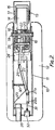
- the armrest assembly comprises an armrest 10 formed by an inverted trough-shaped frame 11 which carries suitably cushioned upholstery 12 and an armrest support structure 13 comprising two parallel support arms 14, 14' pivotally connected at one end to a first support bracket 15 to be mounted on the seat and pivotally connected at their opposite ends to a second support bracket 16 of U-shaped cross-section on which the armrest frame 11 is supported.
- the arms 14, 14' and bracket 15 are contained within a protective housing 17.
- connection of the second support bracket 16 to the support arm 14 comprises a pivot shaft 18 which also passes through the rearward end of the armrest frame 11.
- the support arm 14' pivotally engages the second support bracket 16 via a shaft 19.
- arm 14' carries a first toothed segment 20, conveniently in the form of part of a pinion, which engages a second toothed segment 21 shaped to complement the first toothed segment 20 and mounted on a slider 22 which is slidably mounted on the pivot shaft 18.
- a second shaft 23, parallel to the pivot shaft 18, passes through the slider 22 into engagement at its ends with the second support bracket 16. Accordingly, the U-shaped bracket 16 forms a parallelogram-structure with the two support arms 14, 14' and the first support bracket 15 and therefore is maintained in a constant relationship to the vertical as the support arms pivot upwardly or downwardly.
- An armrest swing stop 24 mounted on the armrest frame 11 engages the U-shaped bracket 16 to support the armrest relative to the bracket 16, and a locking catch 25 on the armrest frame 11 is spring-biassed into locking engagement with the U-shaped bracket 16 to lock the armrest frame 11 relative to the bracket 16, and hence to the support arms 14, 14' via the inter-engaging first and second toothed segments 20, 21.
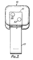
- a mechanism for releasing the second toothed segment 21 from the first toothed segment 20 by movement of the slider 22 along the shafts 18, 23, comprises a system of levers operated from a first push button 26 at the forward end of the armrest.
- This system of levers comprises a bell crank lever 27 pivoted on a pivot pin 28 extending perpendicular to the length of the armrest frame 11 and disposed vertically when the frame 11 is horizontal, one end of the bell crank lever being pivotally and slidably connected to the slider 22.
- the opposite or forward end of the bell crank lever 27 has a pivot connection 27a adjacent one corner of a triangular plate 29 of which a second corner is supported by a pivot pin 29a on the frame 11, and the third corner is engaged by the first push button 26.
- the catch 25 for connecting the armrest frame 11 releasably to the U-shaped bracket 16 comprises a bell crank catch lever having a catch hook 25a at one end for engagement with the U-shaped bracket 16 and is connected at its opposite end to a push rod 31 extending longitudinally through the armrest frame 11 to a second push button 32 slidably mounted at the forward end of the armrest below the first push button 26, and biassed by a spring 33 in a forward direction.
- the bell crank lever 27 is biassed by the spring 30 to a position in which the two toothed segments 20, 21 engage one another so that upon release of the first push button 26, interengagement of the two toothed segments will again lock the parallelogram linkage and prevent further upward or downward movement of the armrest and holding the armrest at any one of a plurality of heights corresponding to those at which the toothed segments 20, 21 engage each other.
- the teeth of two segments are so dimensioned as to permit locking of the armrest in any selected one of nine vertical positions to give nine discrete steps of movement of the armrest in the horizontal mode.
- the locking catch 25 in its relation to the U-shaped bracket is such as to allow 10° of free swinging movement in an upward direction from the position shown in Figure 1 to the position of the armrest in which hook 25a engages the U-shaped bracket 16. This enables the armrest to be aligned with the seat cushion when the armrest has been dropped to its lowest position in which it engages some form of stop on the cushion frame. The arrangement allows the armrest to.
- the seat cushion be lowered to form a lateral extension of the seat cushion (for example for a child to sit on) and to remain in contact with the stop in the event that the seat cushion is tilted independently of the backrest through an angle within the 10° freedom of movement of the armrest.
- the armrest can be formed intearallv with the U-shaDed bracket 16.
Landscapes
- Engineering & Computer Science (AREA)
- Health & Medical Sciences (AREA)
- Dentistry (AREA)
- General Health & Medical Sciences (AREA)
- Aviation & Aerospace Engineering (AREA)
- Transportation (AREA)
- Mechanical Engineering (AREA)
- Seats For Vehicles (AREA)
- Chairs For Special Purposes, Such As Reclining Chairs (AREA)
- Passenger Equipment (AREA)
- Transmission Devices (AREA)
- Automobile Manufacture Line, Endless Track Vehicle, Trailer (AREA)
- Gripping Jigs, Holding Jigs, And Positioning Jigs (AREA)
- Jib Cranes (AREA)
- Massaging Devices (AREA)
- Electrophonic Musical Instruments (AREA)
Claims (3)
Priority Applications (1)
| Application Number | Priority Date | Filing Date | Title |
|---|---|---|---|
| AT79302052T ATE1620T1 (de) | 1978-11-01 | 1979-10-01 | Armlehne fuer einen sitz. |
Applications Claiming Priority (2)
| Application Number | Priority Date | Filing Date | Title |
|---|---|---|---|
| GB7842780A GB2032770A (en) | 1978-11-01 | 1978-11-01 | Adjustable armrests |
| GB4278078 | 1978-11-01 |
Publications (2)
| Publication Number | Publication Date |
|---|---|
| EP0010867A1 EP0010867A1 (fr) | 1980-05-14 |
| EP0010867B1 true EP0010867B1 (fr) | 1982-10-06 |
Family
ID=10500731
Family Applications (1)
| Application Number | Title | Priority Date | Filing Date |
|---|---|---|---|
| EP79302052A Expired EP0010867B1 (fr) | 1978-11-01 | 1979-10-01 | Accoudoir pour un siège |
Country Status (13)
| Country | Link |
|---|---|
| US (1) | US4311338A (fr) |
| EP (1) | EP0010867B1 (fr) |
| JP (1) | JPS5563617A (fr) |
| AT (1) | ATE1620T1 (fr) |
| AU (1) | AU5218779A (fr) |
| BE (1) | BE879767A (fr) |
| BR (1) | BR7907019A (fr) |
| CA (1) | CA1126149A (fr) |
| DE (2) | DE2963816D1 (fr) |
| ES (1) | ES485572A1 (fr) |
| FR (1) | FR2440842A1 (fr) |
| GB (1) | GB2032770A (fr) |
| IT (1) | IT1124392B (fr) |
Cited By (6)
| Publication number | Priority date | Publication date | Assignee | Title |
|---|---|---|---|---|
| DE4310454C1 (de) * | 1993-03-31 | 1994-10-13 | Daimler Benz Ag | Armlehne für Fahrzeugsitze |
| DE19701388A1 (de) * | 1997-01-16 | 1998-07-23 | Grammer Ag | Armlehne für einen Fahrzeugsitz |
| USD688502S1 (en) | 2012-09-20 | 2013-08-27 | Steelcase Inc. | Arm assembly |
| USD688907S1 (en) | 2012-09-20 | 2013-09-03 | Steelcase Inc. | Arm assembly |
| US8967724B2 (en) | 2012-09-20 | 2015-03-03 | Steelcase Inc. | Chair arm assembly |
| EP4711274A1 (fr) * | 2024-09-13 | 2026-03-18 | B/E Aerospace, Inc. | Mécanisme de verrouillage d'accoudoir de siège |
Families Citing this family (58)
| Publication number | Priority date | Publication date | Assignee | Title |
|---|---|---|---|---|
| US4244623A (en) * | 1979-05-08 | 1981-01-13 | Uop Inc. | Multi-position armrest |
| JPS58172757A (ja) * | 1982-04-02 | 1983-10-11 | Fujitsu Ltd | ル−プカウンタ付プログラムカウンタ |
| JPS58175231A (ja) * | 1982-04-07 | 1983-10-14 | Toshiba Corp | 速動型陰極構体及びその製造方法 |
| US4496190A (en) * | 1983-02-10 | 1985-01-29 | Uop Inc. | Parallel folding armrest |
| US4598948A (en) * | 1983-10-21 | 1986-07-08 | Prince Corporation | Vehicle armrest support |
| US4659135A (en) * | 1984-01-20 | 1987-04-21 | Schmelzer Corporation | Adjustable arm rest |
| US4674790A (en) * | 1984-01-20 | 1987-06-23 | Schmelzer Corporation | Adjustable arm rest and console assembly |
| DE3534131A1 (de) * | 1985-09-25 | 1987-04-02 | Grammer Sitzsysteme Gmbh | Sitz mit verstellbaren armlehnen |
| JPS62124350A (ja) * | 1985-11-20 | 1987-06-05 | Matsushita Electric Ind Co Ltd | リンク装置 |
| US4674797A (en) * | 1986-03-25 | 1987-06-23 | Ikeda Bussan Co., Ltd. | Angular position adjustable headrest |
| US4768797A (en) * | 1987-01-28 | 1988-09-06 | Everest & Jennings | Folding wheelchair having adjustable wheels and armrests |
| DE3734046A1 (de) * | 1987-10-08 | 1989-04-20 | Daimler Benz Ag | Kraftwagensitz mit einer winkelveraenderlichen rueckenlehne |
| US4968095A (en) * | 1987-11-23 | 1990-11-06 | Moyers, Inc. | Seat back arm recliner |
| US4872727A (en) * | 1988-10-05 | 1989-10-10 | Rye Ralph K | Adjustable armed chair |
| US4948541A (en) * | 1988-10-27 | 1990-08-14 | Stephen Beck | Method of forming an arm rest for a chair having a tubular passageway for containing control mechanisms |
| US4946226A (en) * | 1989-07-24 | 1990-08-07 | Hoover Universal, Inc. | Vehicle seat assembly with attitude adjustable armrest |
| US5169207A (en) * | 1991-09-18 | 1992-12-08 | Rye Ralph K | Cable tension height adjustable arm rests |
| US5265938A (en) * | 1991-12-05 | 1993-11-30 | Westinghouse Electric Corp. | Adjustable arm for a chair |
| US5292118A (en) * | 1992-01-31 | 1994-03-08 | Huffy Corporation | Basketball backboard elevator system |
| KR100334316B1 (ko) | 1992-06-15 | 2002-10-11 | 헤르만밀러인코퍼레이티드 | 사무용의자의지지장치및제조방법 |
| FR2696387B1 (fr) * | 1992-10-02 | 1994-12-02 | Matra Automobile | Accoudoir de siège à inclinaisons multiples pour siège de véhicule. |
| US5326154A (en) * | 1992-11-17 | 1994-07-05 | Quickie Designs Inc. | Single-post, height-adjustable and removable armrest apparatus for a wheelchair |
| US5362131A (en) * | 1993-03-23 | 1994-11-08 | Lear Seating Corporation | Protective cover for a hinge joint |
| US5599067A (en) * | 1995-06-07 | 1997-02-04 | Herman Miller, Inc. | Adjustable arm rest assembly |
| US5667277A (en) * | 1995-06-07 | 1997-09-16 | Herman Miller Inc. | Height adjustable arm rest assembly |
| US5941603A (en) * | 1997-01-16 | 1999-08-24 | Grammer Ag | Vehicle seat armrest |
| US5924664A (en) * | 1997-03-12 | 1999-07-20 | Ergo View Technologies Corp. | Keyboard support mechanism |
| US5795026A (en) * | 1997-06-06 | 1998-08-18 | Haworth, Inc. | Height adjustable chair arm |
| US5931537A (en) * | 1997-09-30 | 1999-08-03 | Gollin & Co., Inc. | Adjustable chair arm assembly |
| US6361114B1 (en) | 2000-01-06 | 2002-03-26 | Dura Global Technologies, Inc. | Self-leveling chair arm |
| DE10006075A1 (de) * | 2000-02-11 | 2002-01-17 | Schwab Technik Gmbh | Armauflage für einen Sitz |
| US6460932B1 (en) | 2000-06-09 | 2002-10-08 | Krueger International, Inc. | Arm height adjustment mechanism for a chair |
| FR2810596B1 (fr) * | 2000-06-26 | 2002-10-31 | Ecia Equip Composants Ind Auto | Module d'accoudoir pour vehicule automobile et vehicule automobile correspondant |
| ITTO20030123A1 (it) * | 2003-02-19 | 2004-08-20 | Pro Cord Spa | Gruppo di bracciolo per una sedia. |
| US6899308B2 (en) * | 2003-07-31 | 2005-05-31 | Agency For Science, Technology And Research | Passive gravity-compensating mechanisms |
| US20050189807A1 (en) * | 2004-02-27 | 2005-09-01 | Norman Christopher J. | Chair with functional armrest |
| US20050264045A1 (en) * | 2004-05-10 | 2005-12-01 | Sears Manufacturing Company | Stowable armrest for vehicle seat |
| US8840188B2 (en) | 2004-07-07 | 2014-09-23 | Humanscale Corporation | Movable arm pad |
| WO2006017065A2 (fr) | 2004-07-07 | 2006-02-16 | Humanscale Corporation | Bras de fauteuil ergonomique |
| EP1676744A1 (fr) * | 2004-12-31 | 2006-07-05 | Grupo Antolin Ingenieria, S.A. | Accoudoir réglable en hauteur pour une portière de véhicule automobile |
| US7644721B2 (en) * | 2005-01-14 | 2010-01-12 | Charles Hoberman | Synchronized four-bar linkages |
| JP4522316B2 (ja) * | 2005-05-13 | 2010-08-11 | カルソニックカンセイ株式会社 | 車両用アームレストロック部構造 |
| US7331883B2 (en) * | 2005-09-27 | 2008-02-19 | Russell Corporation | Spinning nut basketball elevator system |
| US7335119B2 (en) * | 2005-09-29 | 2008-02-26 | Russell Corporation | Ratchet elevator system |
| FR2896736A1 (fr) * | 2006-01-30 | 2007-08-03 | Fonderie Et Plasturgie Sa | Dispositif d'appui notamment pour un vehicule automobile. |
| US20090079228A1 (en) * | 2007-09-25 | 2009-03-26 | International Automotive Components Group North America, Inc. | Height adjustable armrest assembly |
| US9706845B2 (en) | 2012-09-20 | 2017-07-18 | Steelcase Inc. | Chair assembly |
| US11304528B2 (en) | 2012-09-20 | 2022-04-19 | Steelcase Inc. | Chair assembly with upholstery covering |
| DE102013106708B4 (de) * | 2013-06-26 | 2016-02-11 | Grammer Ag | Fahrzeugsitz und Nutzkraftfahrzeug mit wenigstens einem Fahrzeugsitz |
| DE102014005620B4 (de) | 2014-04-16 | 2016-11-03 | Grammer Ag | Staubunempfindliche Gleitschiene |
| US9844268B2 (en) * | 2015-03-16 | 2017-12-19 | Aaron DeJule | Sitting apparatus |
| US10421379B2 (en) * | 2016-03-30 | 2019-09-24 | Ford Global Technologies Llc | Adjustable armrest |
| DE102016105751A1 (de) * | 2016-03-30 | 2017-10-05 | Bock 1 Gmbh & Co. Kg | Höhenverstellbare Armlehne |
| FR3071786B1 (fr) * | 2017-10-02 | 2020-01-10 | Renault S.A.S. | Siege de vehicule equipe d'un accoudoir mobile |
| EP3608169B1 (fr) * | 2018-08-07 | 2022-01-12 | Clerprem S.p.A. | Appareil avec élément pivotant à inclinaison réglable, en particulier un accoudoir de véhicule |
| US10737602B2 (en) * | 2018-11-07 | 2020-08-11 | Ford Global Technologies, Llc | Deployable armrest |
| US10870489B2 (en) * | 2019-05-24 | 2020-12-22 | B/E Aerospace, Inc. | Position adjustable armrest assemblies for passenger seats |
| US11478084B2 (en) | 2020-08-03 | 2022-10-25 | Ami Industries, Inc. | Seat assembly and system |
Family Cites Families (6)
| Publication number | Priority date | Publication date | Assignee | Title |
|---|---|---|---|---|
| FR580260A (fr) * | 1924-04-17 | 1924-11-04 | Machine à calibrer tous produits de forme sphérique ou ovoïde applicable notamment au calibrage des noix en coque | |
| FR1095113A (fr) * | 1953-10-12 | 1955-05-27 | Aerotherm Corp | Siège avec accoudoir escamotable |
| DE1630103A1 (de) * | 1967-05-18 | 1971-08-05 | Bremshey & Co | Armlehne |
| US3489458A (en) * | 1968-06-21 | 1970-01-13 | Hardman Aerospace | Armrest assembly |
| US4165901A (en) * | 1978-03-20 | 1979-08-28 | Milsco Manufacturing Company | Vehicle seat having arm rest adjustment means |
| DE2819866A1 (de) * | 1978-05-05 | 1979-11-08 | Kaessbohrer Fahrzeug Karl | Armlehne fuer die den mittelgang eines omnibusses begrenzenden sitze |
-
1978
- 1978-11-01 GB GB7842780A patent/GB2032770A/en not_active Withdrawn
-
1979
- 1979-10-01 EP EP79302052A patent/EP0010867B1/fr not_active Expired
- 1979-10-01 DE DE7979302052T patent/DE2963816D1/de not_active Expired
- 1979-10-01 AT AT79302052T patent/ATE1620T1/de not_active IP Right Cessation
- 1979-10-15 US US06/084,923 patent/US4311338A/en not_active Expired - Lifetime
- 1979-10-16 CA CA337,662A patent/CA1126149A/fr not_active Expired
- 1979-10-25 DE DE19797930266U patent/DE7930266U1/de not_active Expired
- 1979-10-25 AU AU52187/79A patent/AU5218779A/en not_active Abandoned
- 1979-10-30 IT IT09586/79A patent/IT1124392B/it active
- 1979-10-30 BR BR7907019A patent/BR7907019A/pt unknown
- 1979-10-31 FR FR7927082A patent/FR2440842A1/fr not_active Withdrawn
- 1979-10-31 ES ES485572A patent/ES485572A1/es not_active Expired
- 1979-10-31 BE BE0/197918A patent/BE879767A/fr unknown
- 1979-11-01 JP JP14052279A patent/JPS5563617A/ja active Pending
Cited By (11)
| Publication number | Priority date | Publication date | Assignee | Title |
|---|---|---|---|---|
| DE4310454C1 (de) * | 1993-03-31 | 1994-10-13 | Daimler Benz Ag | Armlehne für Fahrzeugsitze |
| DE19701388A1 (de) * | 1997-01-16 | 1998-07-23 | Grammer Ag | Armlehne für einen Fahrzeugsitz |
| DE19701388C2 (de) * | 1997-01-16 | 1999-05-20 | Grammer Ag | Armlehne für einen Fahrzeugsitz |
| USD688502S1 (en) | 2012-09-20 | 2013-08-27 | Steelcase Inc. | Arm assembly |
| USD688907S1 (en) | 2012-09-20 | 2013-09-03 | Steelcase Inc. | Arm assembly |
| USD689315S1 (en) | 2012-09-20 | 2013-09-10 | Steelcase Inc. | Arm assembly |
| USD699061S1 (en) | 2012-09-20 | 2014-02-11 | Steelcase Inc. | Arm assembly |
| US8967724B2 (en) | 2012-09-20 | 2015-03-03 | Steelcase Inc. | Chair arm assembly |
| US9028001B2 (en) | 2012-09-20 | 2015-05-12 | Steelcase Inc. | Chair arm assembly |
| US9427085B2 (en) | 2012-09-20 | 2016-08-30 | Steelcase Inc. | Chair arm assembly |
| EP4711274A1 (fr) * | 2024-09-13 | 2026-03-18 | B/E Aerospace, Inc. | Mécanisme de verrouillage d'accoudoir de siège |
Also Published As
| Publication number | Publication date |
|---|---|
| DE7930266U1 (de) | 1980-01-24 |
| CA1126149A (fr) | 1982-06-22 |
| FR2440842A1 (fr) | 1980-06-06 |
| ES485572A1 (es) | 1980-06-16 |
| BR7907019A (pt) | 1980-06-17 |
| JPS5563617A (en) | 1980-05-13 |
| EP0010867A1 (fr) | 1980-05-14 |
| BE879767A (fr) | 1980-02-15 |
| ATE1620T1 (de) | 1982-10-15 |
| IT7909586A0 (it) | 1979-10-30 |
| GB2032770A (en) | 1980-05-14 |
| AU5218779A (en) | 1980-05-08 |
| IT1124392B (it) | 1986-05-07 |
| DE2963816D1 (en) | 1982-11-11 |
| US4311338A (en) | 1982-01-19 |
Similar Documents
| Publication | Publication Date | Title |
|---|---|---|
| EP0010867B1 (fr) | Accoudoir pour un siège | |
| US4487390A (en) | Vehicular seat height adjusting device | |
| US4709961A (en) | Self-releasing ratchet-type seat adjustment | |
| US5011225A (en) | Structure of a movable headrest | |
| US4286765A (en) | Vehicle seats | |
| EP0961712B1 (fr) | Dispositif de verrouillage à inertie destiné à un mécanisme de réglage d'un siège de véhicule | |
| US4307913A (en) | Adjustable arm-rest for vehicle seat | |
| EP0061394A1 (fr) | Support femoral réglable pour siège de véhicule | |
| EP0364145B1 (fr) | Ensemble de siège pour un véhicule | |
| US4015877A (en) | Vehicle seat assemblies | |
| JPS62227830A (ja) | 自動車座席の高さ調整装置 | |
| EP0714805B1 (fr) | Siège réglable manuellement pour véhicules | |
| EP0094141B1 (fr) | Dispositif de montage ajustable pour un siège de véhicule | |
| US3954298A (en) | Height adjustment mechanism for suspension seat | |
| JPS60206740A (ja) | 座席 | |
| US4422690A (en) | Seat position control mechanism | |
| US4074886A (en) | Height adjustment mechanism for a vehicle seat | |
| US4739959A (en) | Adjustable seat | |
| EP0410814B1 (fr) | Siège d'automobile à mécanisme facilitant l'entrée | |
| EP1475267B1 (fr) | Siège de sécurité pour enfant | |
| JPS6338842Y2 (fr) | ||
| GB2368272A (en) | Weight responsive child safety seat | |
| US2246076A (en) | Swivel seat mechanism | |
| GB2349077A (en) | Vehicle seat height adjustment mechanism. | |
| JPS6364329B2 (fr) |
Legal Events
| Date | Code | Title | Description |
|---|---|---|---|
| PUAI | Public reference made under article 153(3) epc to a published international application that has entered the european phase |
Free format text: ORIGINAL CODE: 0009012 |
|
| AK | Designated contracting states |
Designated state(s): AT DE NL SE |
|
| 17P | Request for examination filed | ||
| GRAA | (expected) grant |
Free format text: ORIGINAL CODE: 0009210 |
|
| AK | Designated contracting states |
Designated state(s): AT DE NL SE |
|
| PG25 | Lapsed in a contracting state [announced via postgrant information from national office to epo] |
Ref country code: NL Effective date: 19821006 |
|
| REF | Corresponds to: |
Ref document number: 1620 Country of ref document: AT Date of ref document: 19821015 Kind code of ref document: T |
|
| REF | Corresponds to: |
Ref document number: 2963816 Country of ref document: DE Date of ref document: 19821111 |
|
| NLV1 | Nl: lapsed or annulled due to failure to fulfill the requirements of art. 29p and 29m of the patents act | ||
| PG25 | Lapsed in a contracting state [announced via postgrant information from national office to epo] |
Ref country code: AT Effective date: 19831001 |
|
| PG25 | Lapsed in a contracting state [announced via postgrant information from national office to epo] |
Ref country code: SE Effective date: 19831002 |
|
| PG25 | Lapsed in a contracting state [announced via postgrant information from national office to epo] |
Ref country code: DE Effective date: 19840703 |
|
| EUG | Se: european patent has lapsed |
Ref document number: 79302052.0 Effective date: 19850607 |
|
| PLBE | No opposition filed within time limit |
Free format text: ORIGINAL CODE: 0009261 |
|
| STAA | Information on the status of an ep patent application or granted ep patent |
Free format text: STATUS: NO OPPOSITION FILED WITHIN TIME LIMIT |