EP0010912A1 - Verbesserungen an Ingredienzienbehältern für Verkaufsautomaten - Google Patents
Verbesserungen an Ingredienzienbehältern für Verkaufsautomaten Download PDFInfo
- Publication number
- EP0010912A1 EP0010912A1 EP79302294A EP79302294A EP0010912A1 EP 0010912 A1 EP0010912 A1 EP 0010912A1 EP 79302294 A EP79302294 A EP 79302294A EP 79302294 A EP79302294 A EP 79302294A EP 0010912 A1 EP0010912 A1 EP 0010912A1
- Authority
- EP
- European Patent Office
- Prior art keywords
- neck
- nozzle
- assembly
- container
- valve
- Prior art date
- Legal status (The legal status is an assumption and is not a legal conclusion. Google has not performed a legal analysis and makes no representation as to the accuracy of the status listed.)
- Granted
Links
- 239000004615 ingredient Substances 0.000 title claims abstract description 28
- 230000000717 retained effect Effects 0.000 claims description 5
- 210000001364 upper extremity Anatomy 0.000 claims description 4
- 230000013011 mating Effects 0.000 claims description 2
- 235000013361 beverage Nutrition 0.000 description 3
- 244000299461 Theobroma cacao Species 0.000 description 2
- 239000006071 cream Substances 0.000 description 2
- 230000005294 ferromagnetic effect Effects 0.000 description 2
- 239000000843 powder Substances 0.000 description 2
- 244000269722 Thea sinensis Species 0.000 description 1
- 235000009470 Theobroma cacao Nutrition 0.000 description 1
- 230000000903 blocking effect Effects 0.000 description 1
- 235000019219 chocolate Nutrition 0.000 description 1
- 230000000694 effects Effects 0.000 description 1
- 230000005291 magnetic effect Effects 0.000 description 1
- 238000000034 method Methods 0.000 description 1
- 239000000203 mixture Substances 0.000 description 1
- 238000012856 packing Methods 0.000 description 1
- 239000000837 restrainer Substances 0.000 description 1
- XLYOFNOQVPJJNP-UHFFFAOYSA-N water Substances O XLYOFNOQVPJJNP-UHFFFAOYSA-N 0.000 description 1
Images

Classifications
-
- B—PERFORMING OPERATIONS; TRANSPORTING
- B67—OPENING, CLOSING OR CLEANING BOTTLES, JARS OR SIMILAR CONTAINERS; LIQUID HANDLING
- B67D—DISPENSING, DELIVERING OR TRANSFERRING LIQUIDS, NOT OTHERWISE PROVIDED FOR
- B67D3/00—Apparatus or devices for controlling flow of liquids under gravity from storage containers for dispensing purposes
- B67D3/04—Liquid-dispensing taps or cocks adapted to seal and open tapping holes of casks, e.g. for beer
- B67D3/043—Liquid-dispensing taps or cocks adapted to seal and open tapping holes of casks, e.g. for beer with a closing element having a linear movement, in a direction perpendicular to the seat
-
- A—HUMAN NECESSITIES
- A47—FURNITURE; DOMESTIC ARTICLES OR APPLIANCES; COFFEE MILLS; SPICE MILLS; SUCTION CLEANERS IN GENERAL
- A47J—KITCHEN EQUIPMENT; COFFEE MILLS; SPICE MILLS; APPARATUS FOR MAKING BEVERAGES
- A47J31/00—Apparatus for making beverages
- A47J31/40—Beverage-making apparatus with dispensing means for adding a measured quantity of ingredients, e.g. coffee, water, sugar, cocoa, milk, tea
- A47J31/404—Powder dosing devices
-
- B—PERFORMING OPERATIONS; TRANSPORTING
- B67—OPENING, CLOSING OR CLEANING BOTTLES, JARS OR SIMILAR CONTAINERS; LIQUID HANDLING
- B67D—DISPENSING, DELIVERING OR TRANSFERRING LIQUIDS, NOT OTHERWISE PROVIDED FOR
- B67D3/00—Apparatus or devices for controlling flow of liquids under gravity from storage containers for dispensing purposes
- B67D3/0019—Apparatus or devices for controlling flow of liquids under gravity from storage containers for dispensing purposes using ingredient cartridges
-
- G—PHYSICS
- G07—CHECKING-DEVICES
- G07F—COIN-FREED OR LIKE APPARATUS
- G07F13/00—Coin-freed apparatus for controlling dispensing or fluids, semiliquids or granular material from reservoirs
- G07F13/06—Coin-freed apparatus for controlling dispensing or fluids, semiliquids or granular material from reservoirs with selective dispensing of different fluids or materials or mixtures thereof
-
- G—PHYSICS
- G07—CHECKING-DEVICES
- G07F—COIN-FREED OR LIKE APPARATUS
- G07F13/00—Coin-freed apparatus for controlling dispensing or fluids, semiliquids or granular material from reservoirs
- G07F13/06—Coin-freed apparatus for controlling dispensing or fluids, semiliquids or granular material from reservoirs with selective dispensing of different fluids or materials or mixtures thereof
- G07F13/065—Coin-freed apparatus for controlling dispensing or fluids, semiliquids or granular material from reservoirs with selective dispensing of different fluids or materials or mixtures thereof for drink preparation
Definitions
- the present invention relates to ingredient containers for vending machines.
- a beverage vending machine includes a number of containers each of which contains a beverage forming ingredient in particulate or powdered form.
- succession of containers within a machine may contain respectively tea, coffee, sugar, cream, chocolate and cocoa in powdered form.
- the user operates the machine which dispenses into a cup a measured charge of the selected ingredients for example coffee powder, sugar powder, and cream and then adds hot water to this powdered mixture.
- a disposable container and dispenser assembly for a vending machine which comprises a container body adapted to contain ingredients to be dispensed and valve means for controlling the dispensing of the ingredients whereby the valve means is captive with the container body so that the assembly can be removed from its operative location in the machine for disposal as a single unit.
- a container and dispenser assembly is adapted to be used by inverting the container and valve so that the valve assembly is disposed downwardly and the ingredients can, on operation of the valve, be caused or allowed to flow out of the dispensing nozzle and either under or assisted by gravitational force.
- an ingredient container and dispensing assembly for a dispensing or vending machine, which assembly comprises a container for the ingredients having a neck defining a dispensing opening;
- the weight of the ingredients is to some extent taken by the baffle means spaced upwardly of the valve means, and the whole weight of the ingredients is not concentrated on the valve element itself.
- the restrainer may also serve to prevent lumps of powdered ingredient blocking the valve mechanism.
- the baffle means may be a disc disposed across the container neck and spaced upwardly of the valve member said disc having a plurality of holes for the passage of the ingredients there-through.
- the baffle means may be formed integral with the valve guide member.
- valve guide member and its associated baffle means may be disposed between a shoulder on the internal surface of the neck and the shoulder of the dispensing nozzle and retained therein by means of interengagement means comprising a plurality of arcuate, circumferentially spaced barbs on the outer surface of the container neck and a plurality of mating slots provided in the collar.
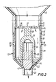
- the container 10 has a downwardly extending neck 11 which supports and carries a dispensing nozzle 12.
- the dispensing neck 11 is provided on the upper part of the neck juxtaposed the shoulders 13 with a plurality of axially extending supporting ribs 14. Downwardly of the supporting ribs 14 the outer surface of the neck is provided with an annular rib 15.
- the lower portion of the neck is rabbeted over the greater part thereof to provide a lower cylindrical inner surface 16 defined at its upper end in an annular shoulder 17.
- neck 11 is provided spaced downwardly of annular rib 15 with a plurality of barbs 18 each barb being disposed circumferentially of the outer surface of the neck and spaced circumferentially one with respect to the other.
- Each barb has a lower inclined face 19 and an upper radial face 20.
- the dispensing nozzle 12 comprises a sleeve 21 adapted to overlay a neck 11 downwardly of rib 15.
- the sleeve 21 is provided with a plurality of circumferentially extended slots 25 each of which is adapted to accommodate a barb 18.
- the upper extremity of sleeve 21 is chamfered on the inner surface at 26 so that on applying the nozzle 12 to the neck 11 the chamfered upper extremity 26 of the nozzle is entered over the lower end of the neck until the chamfered portion 26 abuts inclined surface 19 of barb 18.
- Upward pressure causes the upper part of the sleeve 21 to expand and ride over barb 18 and continued pressure of the nozzle towards the container body results in the upper part of sleeve 21 riding over barb 18 until the upper extremity abuts rib 15 and the barbs 18 snap into their corresponding circumferential slots 25 thereby retaining the nozzle about the neck of the container.
- the nozzle and neck assembly are adapted to accommodate a valve block 30 which comprises a substantially cylindrical block 31 which is cut away on diametrically opposed and spaced surfaces to define planar side faces 32. (see FIGURE 3).
- the block is provided with an internal bore 33 adapted to accommodate a valve element 34.
- the bore 33 is opened at its lower end and is closed at its upper end and is disposed substantially co-axially with the neck of the container and the nozzle 23.
- the internal bore 33 is a dimension such that it is open to each of the side faces 32.
- the block 30 is domed at its upper end 35 and has an upstanding cruciform spigot 36 extending upwardly therefrom; which spigot 36 carries a disc 37 extending substantially radially of the block axis; the radius of the disc being such as to be a fit with the cylindrical inner surface 16 of neck 11.
- the lower portion of block 30 is provided with a substantially radial flange 39 the side portions of which 40 are cut away to be continuous with planar side faces 32 of block 30.
- Each flange portion 39 has an arcuate outer surface 41 and carries a depending abutment 42 having a curved outer surface 43 continuous with the lower part of flange 39 which defines part of the frustocone itself defined by the inner surface frustoconical portion 22 of nozzle 12.
- the side surfaces 44 of abutment 42 are substantially planar, the abutments 42 are disposed diametrically one with respect to the other of the axis of block 30.
- the internal surface 45 of each abutment is curved to provide a continuation of the curved inner surface of the internal bore 33 in block 30.
- the block 30 is disposed within the nozzle and neck assembly as shown in FIGURE 2 with the periphery of disc 37 abutting shoulder 17 and the surface 43 of the abutment 42 engaging with the internal surface of the frustoconical portion 22 of neck 11 so that when the dispensing nozzle 12 is snapped into engagement with neck 11 valve block 30 is positively retained in position within the neck and nozzle assembly.
- the valve element 34 comprises a substantially cylindrical ferromagnetic block, the outer surface of which is chamfered at 46 to provide a frustoconical valve seat 47, the element being a sufficient weight that in the rest position it rests against the valve seat 24 to close the dispensing nozzle from the container.
- valve element 34 On the Application of a magnetic field the ferromagnetic valve element 34 is excited and lifted from its valve seat to allow ingredients to flow from the container via the holes 38 in disc 37 either side of the valve block 30 past the side walls 32 and out of the nozzle 23. On deenergising valve element 34 the element under its own weight moves downwardly until it engages with seat 24 and shuts off the flow of ingredient from the nozzle 23.
- the disc 38 serves to support the greater weight of ingredient within the container and to take some of the weight from the valve element to allow it to move more freely in operation.
Landscapes
- Engineering & Computer Science (AREA)
- Physics & Mathematics (AREA)
- General Physics & Mathematics (AREA)
- Mechanical Engineering (AREA)
- Food Science & Technology (AREA)
- Closures For Containers (AREA)
- Vending Machines For Individual Products (AREA)
- Beverage Vending Machines With Cups, And Gas Or Electricity Vending Machines (AREA)
Priority Applications (1)
| Application Number | Priority Date | Filing Date | Title |
|---|---|---|---|
| AT79302294T ATE3916T1 (de) | 1978-10-24 | 1979-10-22 | Verbesserungen an ingredienzienbehaeltern fuer verkaufsautomaten. |
Applications Claiming Priority (2)
| Application Number | Priority Date | Filing Date | Title |
|---|---|---|---|
| GB4176778 | 1978-10-24 | ||
| GB7841767 | 1978-10-24 |
Publications (2)
| Publication Number | Publication Date |
|---|---|
| EP0010912A1 true EP0010912A1 (de) | 1980-05-14 |
| EP0010912B1 EP0010912B1 (de) | 1983-06-22 |
Family
ID=10500553
Family Applications (1)
| Application Number | Title | Priority Date | Filing Date |
|---|---|---|---|
| EP79302294A Expired EP0010912B1 (de) | 1978-10-24 | 1979-10-22 | Verbesserungen an Ingredienzienbehältern für Verkaufsautomaten |
Country Status (5)
| Country | Link |
|---|---|
| EP (1) | EP0010912B1 (de) |
| AT (1) | ATE3916T1 (de) |
| DE (1) | DE2965750D1 (de) |
| DK (1) | DK447079A (de) |
| IE (1) | IE48858B1 (de) |
Cited By (3)
| Publication number | Priority date | Publication date | Assignee | Title |
|---|---|---|---|---|
| EP0022589A3 (en) * | 1979-07-11 | 1982-04-07 | Cadbury Schweppes Limited | Beverage dispenser comprising a liquid dispensing package and valve, a manifold and a diluent tank |
| US4523697A (en) * | 1979-07-11 | 1985-06-18 | Cadbury Schweppes Limited | Liquid dispensing package |
| CN116113596A (zh) * | 2020-07-31 | 2023-05-12 | Itap国际有限责任公司 | 用于容器的分配装置,优选是用于液体的柔性容器,以及包括容器和所述装置的组件 |
Families Citing this family (3)
| Publication number | Priority date | Publication date | Assignee | Title |
|---|---|---|---|---|
| CA2303077C (en) | 1997-10-08 | 2007-05-15 | Minnesota Mining And Manufacturing Company | Gravity feed fluid dispensing valve |
| US6223791B1 (en) | 1999-10-21 | 2001-05-01 | 3M Innovative Properties Company | Gravity feed fluid dispensing valve |
| US6450214B1 (en) | 2001-08-31 | 2002-09-17 | 3M Innovative Properties Company | Gravity feed fluid dispensing valve |
Citations (5)
| Publication number | Priority date | Publication date | Assignee | Title |
|---|---|---|---|---|
| US1832692A (en) * | 1928-07-20 | 1931-11-17 | Thomas N Deligianes | Dispensing device |
| US3200997A (en) * | 1962-07-11 | 1965-08-17 | Lipton Inc Thomas J | Beverage dispenser |
| US3204832A (en) * | 1962-08-24 | 1965-09-07 | Barber S Morgan | Material dispensing apparatus |
| FR2014254A1 (de) * | 1968-06-26 | 1970-04-17 | Perfix Pty Ltd | |
| FR2373843A1 (fr) * | 1976-12-07 | 1978-07-07 | Venlease Group Ltd | Ensemble recipient-distributeur a jeter apres usage pour distributeurs automatiques |
-
1979
- 1979-10-22 DE DE7979302294T patent/DE2965750D1/de not_active Expired
- 1979-10-22 AT AT79302294T patent/ATE3916T1/de not_active IP Right Cessation
- 1979-10-22 IE IE2015/79A patent/IE48858B1/en unknown
- 1979-10-22 EP EP79302294A patent/EP0010912B1/de not_active Expired
- 1979-10-23 DK DK447079A patent/DK447079A/da not_active Application Discontinuation
Patent Citations (5)
| Publication number | Priority date | Publication date | Assignee | Title |
|---|---|---|---|---|
| US1832692A (en) * | 1928-07-20 | 1931-11-17 | Thomas N Deligianes | Dispensing device |
| US3200997A (en) * | 1962-07-11 | 1965-08-17 | Lipton Inc Thomas J | Beverage dispenser |
| US3204832A (en) * | 1962-08-24 | 1965-09-07 | Barber S Morgan | Material dispensing apparatus |
| FR2014254A1 (de) * | 1968-06-26 | 1970-04-17 | Perfix Pty Ltd | |
| FR2373843A1 (fr) * | 1976-12-07 | 1978-07-07 | Venlease Group Ltd | Ensemble recipient-distributeur a jeter apres usage pour distributeurs automatiques |
Cited By (3)
| Publication number | Priority date | Publication date | Assignee | Title |
|---|---|---|---|---|
| EP0022589A3 (en) * | 1979-07-11 | 1982-04-07 | Cadbury Schweppes Limited | Beverage dispenser comprising a liquid dispensing package and valve, a manifold and a diluent tank |
| US4523697A (en) * | 1979-07-11 | 1985-06-18 | Cadbury Schweppes Limited | Liquid dispensing package |
| CN116113596A (zh) * | 2020-07-31 | 2023-05-12 | Itap国际有限责任公司 | 用于容器的分配装置,优选是用于液体的柔性容器,以及包括容器和所述装置的组件 |
Also Published As
| Publication number | Publication date |
|---|---|
| EP0010912B1 (de) | 1983-06-22 |
| ATE3916T1 (de) | 1983-07-15 |
| DK447079A (da) | 1980-04-25 |
| IE48858B1 (en) | 1985-05-29 |
| DE2965750D1 (en) | 1983-07-28 |
| IE792015L (en) | 1980-04-24 |
Similar Documents
| Publication | Publication Date | Title |
|---|---|---|
| EP0498473B1 (de) | Verfahren um Körnerdünger zu handeln | |
| US6209762B1 (en) | Dispensing package and method of use | |
| US4699299A (en) | Adjustable dispensing closure | |
| EP0191614B1 (de) | Ventil für unter Druck stehende Abgabebehälter | |
| US4424921A (en) | Measured dispenser | |
| EP0126739B1 (de) | Dosierungsvorrichtung zum verabreichen vorbestimmter mengen vorzugsweise von getränken aus einer flasche | |
| NZ272057A (en) | Hopper to applicator rotary actuated poppet valve connector | |
| JP4194242B2 (ja) | エーロゾル粉末弁 | |
| EP0010912B1 (de) | Verbesserungen an Ingredienzienbehältern für Verkaufsautomaten | |
| JPH08502464A (ja) | 流体カップリング装置 | |
| WO2024127368A1 (en) | Appliance for grinding of foodstuffs | |
| EP1598311B1 (de) | Dosiervorrichtung zur Behältermontage | |
| GB2034675A (en) | Valved Dispensing Assemblies | |
| GB1585191A (en) | Disposable drinking cup | |
| US4684046A (en) | Unit dose liquid dispenser having precise dosage capabilities | |
| GB1591803A (en) | Valve dispensing head | |
| US3478934A (en) | Metering apparatus | |
| US6041967A (en) | Rapid connecting assembly for an aerosol can and a dispensing device | |
| RU2675445C1 (ru) | Многопорционное устройство и кассета | |
| US5407105A (en) | Measuring/dispensing device for liquid products | |
| JPH0272091A (ja) | 粘性補償装置を具備するパッケージ | |
| GB2101969A (en) | Dispensing valves | |
| US2101020A (en) | Cream dispenser | |
| USRE24599E (en) | Dispensing valve structure for | |
| IE46177B1 (en) | Valve dispensing head |
Legal Events
| Date | Code | Title | Description |
|---|---|---|---|
| PUAI | Public reference made under article 153(3) epc to a published international application that has entered the european phase |
Free format text: ORIGINAL CODE: 0009012 |
|
| AK | Designated contracting states |
Designated state(s): AT BE CH DE FR IT LU NL SE |
|
| 17P | Request for examination filed |
Effective date: 19801112 |
|
| ITF | It: translation for a ep patent filed | ||
| GRAA | (expected) grant |
Free format text: ORIGINAL CODE: 0009210 |
|
| AK | Designated contracting states |
Designated state(s): AT BE CH DE FR IT LU NL SE |
|
| REF | Corresponds to: |
Ref document number: 3916 Country of ref document: AT Date of ref document: 19830715 Kind code of ref document: T |
|
| REF | Corresponds to: |
Ref document number: 2965750 Country of ref document: DE Date of ref document: 19830728 |
|
| ET | Fr: translation filed | ||
| PLBE | No opposition filed within time limit |
Free format text: ORIGINAL CODE: 0009261 |
|
| STAA | Information on the status of an ep patent application or granted ep patent |
Free format text: STATUS: NO OPPOSITION FILED WITHIN TIME LIMIT |
|
| 26N | No opposition filed | ||
| PGFP | Annual fee paid to national office [announced via postgrant information from national office to epo] |
Ref country code: GB Payment date: 19891031 Year of fee payment: 11 |
|
| ITTA | It: last paid annual fee | ||
| PGFP | Annual fee paid to national office [announced via postgrant information from national office to epo] |
Ref country code: BE Payment date: 19930824 Year of fee payment: 15 |
|
| PGFP | Annual fee paid to national office [announced via postgrant information from national office to epo] |
Ref country code: CH Payment date: 19930903 Year of fee payment: 15 |
|
| PGFP | Annual fee paid to national office [announced via postgrant information from national office to epo] |
Ref country code: LU Payment date: 19930916 Year of fee payment: 15 |
|
| PGFP | Annual fee paid to national office [announced via postgrant information from national office to epo] |
Ref country code: SE Payment date: 19931018 Year of fee payment: 15 |
|
| PGFP | Annual fee paid to national office [announced via postgrant information from national office to epo] |
Ref country code: FR Payment date: 19931026 Year of fee payment: 15 |
|
| PGFP | Annual fee paid to national office [announced via postgrant information from national office to epo] |
Ref country code: AT Payment date: 19931031 Year of fee payment: 15 |
|
| EPTA | Lu: last paid annual fee | ||
| PGFP | Annual fee paid to national office [announced via postgrant information from national office to epo] |
Ref country code: DE Payment date: 19931228 Year of fee payment: 15 |
|
| PG25 | Lapsed in a contracting state [announced via postgrant information from national office to epo] |
Ref country code: LU Free format text: LAPSE BECAUSE OF NON-PAYMENT OF DUE FEES Effective date: 19941022 Ref country code: AT Effective date: 19941022 |
|
| PG25 | Lapsed in a contracting state [announced via postgrant information from national office to epo] |
Ref country code: SE Effective date: 19941023 |
|
| PG25 | Lapsed in a contracting state [announced via postgrant information from national office to epo] |
Ref country code: CH Effective date: 19941031 Ref country code: BE Effective date: 19941031 |
|
| PGFP | Annual fee paid to national office [announced via postgrant information from national office to epo] |
Ref country code: NL Payment date: 19941031 Year of fee payment: 16 |
|
| EAL | Se: european patent in force in sweden |
Ref document number: 79302294.8 |
|
| BERE | Be: lapsed |
Owner name: VGL INDUSTRIES LTD Effective date: 19941031 |
|
| PG25 | Lapsed in a contracting state [announced via postgrant information from national office to epo] |
Ref country code: FR Effective date: 19950630 |
|
| REG | Reference to a national code |
Ref country code: CH Ref legal event code: PL |
|
| PG25 | Lapsed in a contracting state [announced via postgrant information from national office to epo] |
Ref country code: DE Effective date: 19950701 |
|
| EUG | Se: european patent has lapsed |
Ref document number: 79302294.8 |
|
| REG | Reference to a national code |
Ref country code: FR Ref legal event code: ST |
|
| PG25 | Lapsed in a contracting state [announced via postgrant information from national office to epo] |
Ref country code: NL Effective date: 19960501 |
|
| NLV4 | Nl: lapsed or anulled due to non-payment of the annual fee |
Effective date: 19960501 |