EP0010930A1 - Kompressoren des Exzenterspiraltyps - Google Patents
Kompressoren des Exzenterspiraltyps Download PDFInfo
- Publication number
- EP0010930A1 EP0010930A1 EP79302336A EP79302336A EP0010930A1 EP 0010930 A1 EP0010930 A1 EP 0010930A1 EP 79302336 A EP79302336 A EP 79302336A EP 79302336 A EP79302336 A EP 79302336A EP 0010930 A1 EP0010930 A1 EP 0010930A1
- Authority
- EP
- European Patent Office
- Prior art keywords
- diameter
- end plate
- keyways
- scroll member
- compressor housing
- Prior art date
- Legal status (The legal status is an assumption and is not a legal conclusion. Google has not performed a legal analysis and makes no representation as to the accuracy of the status listed.)
- Granted
Links
- 239000012530 fluid Substances 0.000 title claims description 25
- 230000003405 preventing effect Effects 0.000 claims description 14
- 238000010276 construction Methods 0.000 abstract description 3
- 230000013011 mating Effects 0.000 abstract description 2
- 239000003507 refrigerant Substances 0.000 abstract description 2
- 238000007789 sealing Methods 0.000 description 7
- 230000004048 modification Effects 0.000 description 6
- 238000012986 modification Methods 0.000 description 6
- 230000000694 effects Effects 0.000 description 4
- 230000007423 decrease Effects 0.000 description 2
- 230000002093 peripheral effect Effects 0.000 description 2
- 230000002159 abnormal effect Effects 0.000 description 1
- 230000004323 axial length Effects 0.000 description 1
- 238000006243 chemical reaction Methods 0.000 description 1
- 230000006835 compression Effects 0.000 description 1
- 238000007906 compression Methods 0.000 description 1
- 239000013013 elastic material Substances 0.000 description 1
- 238000004519 manufacturing process Methods 0.000 description 1
- 239000000463 material Substances 0.000 description 1
Images


Classifications
-
- F—MECHANICAL ENGINEERING; LIGHTING; HEATING; WEAPONS; BLASTING
- F01—MACHINES OR ENGINES IN GENERAL; ENGINE PLANTS IN GENERAL; STEAM ENGINES
- F01C—ROTARY-PISTON OR OSCILLATING-PISTON MACHINES OR ENGINES
- F01C17/00—Arrangements for drive of co-operating members, e.g. for rotary piston and casing
- F01C17/06—Arrangements for drive of co-operating members, e.g. for rotary piston and casing using cranks, universal joints or similar elements
- F01C17/066—Arrangements for drive of co-operating members, e.g. for rotary piston and casing using cranks, universal joints or similar elements with an intermediate piece sliding along perpendicular axes, e.g. Oldham coupling
-
- F—MECHANICAL ENGINEERING; LIGHTING; HEATING; WEAPONS; BLASTING
- F04—POSITIVE - DISPLACEMENT MACHINES FOR LIQUIDS; PUMPS FOR LIQUIDS OR ELASTIC FLUIDS
- F04C—ROTARY-PISTON, OR OSCILLATING-PISTON, POSITIVE-DISPLACEMENT MACHINES FOR LIQUIDS; ROTARY-PISTON, OR OSCILLATING-PISTON, POSITIVE-DISPLACEMENT PUMPS
- F04C18/00—Rotary-piston pumps specially adapted for elastic fluids
- F04C18/02—Rotary-piston pumps specially adapted for elastic fluids of arcuate-engagement type, i.e. with circular translatory movement of co-operating members, each member having the same number of teeth or tooth-equivalents
- F04C18/0207—Rotary-piston pumps specially adapted for elastic fluids of arcuate-engagement type, i.e. with circular translatory movement of co-operating members, each member having the same number of teeth or tooth-equivalents both members having co-operating elements in spiral form
- F04C18/0215—Rotary-piston pumps specially adapted for elastic fluids of arcuate-engagement type, i.e. with circular translatory movement of co-operating members, each member having the same number of teeth or tooth-equivalents both members having co-operating elements in spiral form where only one member is moving
Definitions
- This invention relates to scroll type fluid compressor units.
- a scroll type apparatus has been well known in the prior art as disclosed in, for example, U.S. Patent No. 801,182 and others, which comprises two scroll members each having an end plate and a spiroidal or involute spiral element. These scroll members are so maintained angularly and radially offset that both of spiral elements interfit to make a plurality of line contacts between spiral curved surfaces thereby to seal off and define at least one fluid pocket.
- the relative orbital motion of these scroll members shifts the line contacts along the spiral curved surfaces and, therefore, the fluid pocket changes in volume.
- the volume of the fluid pocket increases or decreases in dependence on the direction of the orbital motion. Therefore, the scroll-type apparatus is applicable to handle fluids to compress, expand or pump them.
- a scroll-type compressor In comparison with conventional compressors of a piston type, a scroll-type compressor has some advantages such as less number of parts, continuous compression of fluid and others. But, there have been several problems: primarily sealing of the fluid pocket, wearing of the spiral elements, and inlet and outlet porting.
- a scroll-type fluid compressor unit comprising a compressor housing having a front end plate and a rear end plate, a fixed scroll member fixedly disposed within said compressor housing and having first end plate means towhich first wrap means are affixed, an orbiting scroll member orbitably disposed within said compressor housing and having second end plate means to which second wrap means are affixed, said first and second wrap means interfitting at a predetermined angular relationship to make a plurality of line contacts to define at least one sealed off fluid pocket which moves with reduction of volume thereof by the orbital motion of said orbiting scroll member, thereby to compress the fluid in the pocket, wherein a drive shaft is supported by first radial bearing means in said front end plate and outwardly extends through said front end plate, a disk rotor member is mounted on an inner end of said drive shaft and is supported by first thrust bearing means on an inner surface of said front end plate, a drive pin axially projects on a rear surface of said disk rotor member and is radially offset from said
- the rotation preventing means may comprise a ring plate slider member disposed around the axial boss and having a first pair of radial key projections projecting at opposite ends of a diameter thereof on an axial end surface thereof and a second pair of key projections projecting at opposite ends of another diameter perpendicular to the diameter on the other axial end surface thereof.
- Fixed guide means are then fixedly disposed within the compressor housing and have a first pair of keyways in which the first key projections are received to permit the radial movement of the slider member along the first keyways.
- the second end plate of the second scroll member then has a second pair of keyways in which the second pair of key projections are received to permit the radial movement of the slider member along the second keyways.
- the first key projections may be advantageously formed offset from one another so that side surfaces of respective first key projections receiving a relative rotational force between the slider member and the fixed guide means are on the diameter of the ring plate slider member, and the second key projections are formed offset from one another so that side surfaces of respective second key projections receiving a relative rotational force between the slider member and the second scroll member are on the other diameter of the ring plate slider member.
- the first and second pair of key projections may be alternatively formed on the fixed guide means and the second end plate means of the second scroll member, respectively.
- the first and second keyways may be formed in the opposite end surfaces of the ring plate slider members, respectively.
- a refrigerant compressor unit 10 of an embodiment shown includes a compressor housing comprising a front end plate 11, a rear end plate 12 and a cylindrical housing 13 connecting between those end plates.
- the rear end plate 12 is provided with a fluid inlet port 14 and a fluid outlet port 15 formed therethrough.
- a drive shaft 16 is rotatably - supported by a radial needle bearing 17 in the front end plate 11.
- the front end plate 11 has a sleeve portion 18 projecting on the front surface thereof and surrounding the drive shaft 16 to define a shaft seal cavity 20. Within the shaft seal cavity, a shaft seal assembly 19 is assembled on drive shaft 16.
- a pulley (not shown) is rotatably mounted on sleeve portion 18 and is connected with drive shaft 16, in order to transmit an external drive power source (not shown) to drive shaft 16.
- Belt means (not shown) are wound around the pulley.
- a disk rotor 21 is fixedly mounted on an inner end of drive shaft 16 and is born on the inner surface of front end plate 11 through a thrust needle bearing 22 which is disposed concentric with the drive shaft 16.
- the disk rotor 21 is provided with a drive pin 23 projecting on the rear surface thereof.
- the drive pin 23 is radially offset from the drive shaft 16 by a predetermined length.
- Reference numerals 24 and 25 represent a pair of interfitting orbiting and fixed scroll members.
- the orbiting scroll member 24 includes an end circular plate 241 and a wrap means or spiral element 242.affixed onto one end surface of the end plate.
- End plate 241 is provided with a boss 243 projecting on the other end surface thereof and a radial flange 244 radially and integrally extending from the projecting end of the boss.
- the radial flange 244 is supported on the rear end surface of disk rotor 21 by a thrust needle bearing 26 which is disposed concentric with drive pin 23, and drive pin 23 is fitted into the boss 243 with a radial needle bearing 27 therebetween so that orbiting scroll member 24 is rotatably supported on drive pin 23.
- orbiting scroll member 24 moves along a circle of a radius of the length between drive shaft 16 and drive pin 23.
- a bushing 28 of anti-wearing materials may be used as shown in Fig. 1, which is fitted into boss 243 around radial bearing 27 to protect the boss from wearing.
- Means 29 for preventing orbiting scroll member 24 from rotating during the orbital motion is disposed between end plate 241 and radial flange 244 of orbiting scroll member 24.
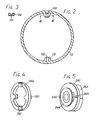
- the cylindrical housing 13 is provided with a pair of projections 131 which inwardly project on the inner surface of the cylindrical housing 13 at opposite ends of a diameter of the cylindrical housing, as shown in Fig. 2.
- Each projection 131 is provided with a..radially extending keyway 132 in an axial rear end surface thereof, as shown in Figs. 2 and 3.
- a ring like slider plate member 29a which has an inner diameter longer than the diameter of the radial flange 244 with another diameter shorter than the inner diameter of the cylindrical housing 13, is disposed around boss 243 and between the projections 131 and the end plate 241.
- the slider member 29a is provided with a pair of keys 291 on the front end surface at opposite ends of a diameter thereof, which are received in the keyways 132 of the projections 131.
- the slider member 29a is also provided with another pair of keys 292 on the rear end surface thereof. These keys 292 are on another diameter perpendicular to the diameter on which keys 291 are.
- End plate 241 of orbiting scroll member 24 is provided with a pair of keyways 245 in the front end surface to receive the keys 292 of the slider member 29a, as shown in Fig. 5.
- the slider member 29a is prevented from rotating, but permitted to move in a radial direction, by key and keyway connection 291-132.
- the orbiting scroll member 24 is prevented from rotating in relation to the slider member 29a, but permitted to move in a radial direction, by key and keyway connection 292-245. Therefore, the orbiting scroll member 24 is permitted to move in two radial directions to one another, and, thus, moves along a circle as a result of movement on the two radial directions but is prevented from rotation. Therefore, the eccentric movement of dirve pin 23 by the rotation of drive shaft 16 effects the orbital motion of orbiting scroll member 24 without rotation.
- the other fixed scroll member 25 also comprises an end circular plate 251 and a wrap means or spiral element 252 affixed on one end surface of the end plate.
- the end plate 251 is provided with a hole or a discharge port 253 formed at a position corresponding to the center of the spiral element 252, and with an annular projection 254 on the rear end surface around the discharge port 253.
- the rear end plate 12 is provided with an annular projection 121 on the inner surface thereof around the outlet port 15.
- the outer radius of the annular projection 121 is selected slightly shorter than the inner radius of the annular projection 254.
- the annular projection 121 is cut away along the outer edge of the projecting end to define an annular recess 122.
- An annular elastic material for example, a rubber ring 30 is fitted into the annular recess 122 and is compressedly held between the interfitted annular projections 121 and 254, so that the fixed scroll member 25 is elastically supported on the annular projection 121 of the rear end plate.
- the rubber ring 30 serves as a seal for sealing off a chamber 31 defined by annular projections 121 and 254 from the interior space 133 of the compressor housing.
- the chamber 31 connects between outlet port 15 and discharge port 253 of fixed scroll member 25.
- the end plate 251 of fixed scroll member 25 is formed with a plurality of cut away portions 255 at the rear end peripheral edge.
- a plurality of projections . 134 are formed on the inner surface of cylindrical housing 13 of the compressor housing and are mated into the cut away portions 255, so that the fixed scroll member 25 is non-rotatably disposed within the compressor housing.
- the chamber portion 33 communicates with inlet port 14.
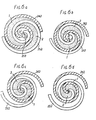
- the introduced fluid is taken into fluid pockets 1 and 2 (which are shown at dotted regions) which are defined by line contacts between orbiting spiral element 242 and fixed spiral element 252, as shown in Fig. 6a.
- the line contacts shift by the orbital motion of orbiting spiral element 242 and, therefore, fluid pockets 1 and 2 angularly and radially move toward the center of spiral elements and decrease their volume, as shown-in Figs. 6b-6d. Therefore, the fluid in each pocket is compressed.
- fluid is again taken into new formed fluid pockets 1 and 2, while old pockets connect-together to form a reduced pocket and the already taken and compressed fluid is discharged from the pocket through discharge port 253.
- disk rotor 21 fixedly mounted on drive shaft 16 is supported through thrust bearing 22 on front end plate 11, drive shaft 16 is securely and non-vibratingly supported by the use of a single needle bearing as a radial bearing.
- the radial sealing force at each line contact between fixed and orbiting spiral elements 252 and 242. is determined by the radius of the orbital motion of orbiting scroll member 24 or the offset length between drive shaft 16 and drive pin 23, and the pitch and thickness of each of fixed and orbiting spiral elements 252 and 242.
- the distance between drive shaft 16 and drive pin 23 is preferably selected slightly larger than the half of the dimensional difference between the pitch of each spiral element and the total dimension of thickness of fixed and orbiting spiral elements.
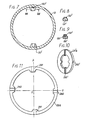
- slider member 29'a can be provided with not two pair of keys but two pair of keyways 291' and 292'. Accordingly, projections 131' of cylindrical housing 13 are provided with not a pair of keyways but a pair of keys 132' which are received in keyways 291' of slider member 29'a. Key 132' can be formed integrally with projection 131', but it may be formed as a separate member which is secured to the projection 131' by a pin 135, as shown in Fig. 9. It will be understood that the end plate 241 of orbiting scroll member 24 is also provided with not keyways but a pair of keys (not shown) which are received in the keyways 292' of the slider member 29'a.
- the arrangement serves for preventing the orbiting scroll member from rotating, but for permitting it to effect the orbital motion, similar to the embodiment in Figs. 1-5.
- a pair of keys 291 of the slider member 29a are advantageously offset from one another so that side surfaces of respective keys receiving a relative rotational force between the slider member and projections 131 of the cylindrical housing are on a diameter 0-X of the slider member.
- Another pair of keys 292 are similarly offset from one another so that side surfaces of respective keys receiving a relative rotational force between the slider member and orbiting scroll member 24 are on another diameter 0-Y of the slider member.
- keyways 132 and 245 of the projections 131 and the orbiting scroll member 24 are formed offset to receive keys 291 and 292, respectively.
- the arrangement provides a greater rotation preventing force by a smaller contact surface of key and keyway connection.
- the contact area S1 between the key and the keyway for preventing the rotation of the slider member in the direction as shown by an arrow A will be determined as follows; assuming that the rotational torque of the key 291 is T and that the resultant force of reactions at various points of the contact surface of the key is F 1 at a point P on the contact surface of a distance r from the center 0, where, ⁇ is an angle between OP and OX , P, being a surface pressure between contact surfaces of key and keyways.
- contact area between key and keyway can be made smaller. This means that the length of each of key and keyways can be formed shorter.
- FIG. 13 and 14 another embodiment as shown is similar to the embodiment in Fig. 1, except that a ring 36 having a pair of keyways 361 is used in place of projections 131 in Fig. 1.
- the ring 36 has an outer diameter equal to the inner diameter of the cylindrical housing 13 and an inner diameter slightly larger than the diameter of the radial flange. If the keyways 361 are desired to be formed longer, radially inwardly extending portions may be formed on the inner surface at opposite ends of a diameter of the ring, on which portions keyways are formed. In this arrangement, the inner diameter of the ring should be long sufficient to permit the radial flange to pass through the ring in the inclined condition. It will be understood that the inner contour of the ring may be formed oval.
- the cylindrical housing 13 is provided with an annular rim 136 on the inner surface thereof.
- a cylindrical body-37 having an outer diameter equal to the inner diameter of the cylindrical housing and having an inner diameter longer than the outer diameter of the disk rotor 21 is fitted into the cylindrical housing at the front side.
- the ring 36 is held between the annular rim 136 and the cylindrical body 37 to be prevented from its axial movement.
- the front end of the cylindrical body 37 engages with the inner surface of the front end plate 11, so that the cylindrical body 37 is backed up by the front end plate.
- the ring 36 is prevented from rotating by means of such as pins 38 which extend through the ring 36 and the annular rim 136, or by means of mating projections and recesses connections.
- the pair of keyways 361 of the ring 36 receive the pair of keys 291 of slider member 29a to guide the radial movement of the slider member.
- the rear end plate 12 can be formed integral with the cylindrical housing 13, and assembling operation is simplified in comparison with the embodiment in Fig. 1.
Landscapes
- Engineering & Computer Science (AREA)
- Mechanical Engineering (AREA)
- General Engineering & Computer Science (AREA)
- Rotary Pumps (AREA)
Applications Claiming Priority (4)
| Application Number | Priority Date | Filing Date | Title |
|---|---|---|---|
| JP134175/78 | 1978-10-30 | ||
| JP13417378A JPS5560686A (en) | 1978-10-30 | 1978-10-30 | Positive-displacement fluid compressor |
| JP13417578A JPS5560688A (en) | 1978-10-30 | 1978-10-30 | Positive-displacement fluid compressor |
| JP134173/78 | 1978-10-30 |
Publications (2)
| Publication Number | Publication Date |
|---|---|
| EP0010930A1 true EP0010930A1 (de) | 1980-05-14 |
| EP0010930B1 EP0010930B1 (de) | 1983-09-21 |
Family
ID=26468350
Family Applications (1)
| Application Number | Title | Priority Date | Filing Date |
|---|---|---|---|
| EP79302336A Expired EP0010930B1 (de) | 1978-10-30 | 1979-10-25 | Kompressoren des Exzenterspiraltyps |
Country Status (5)
| Country | Link |
|---|---|
| US (1) | US4325683A (de) |
| EP (1) | EP0010930B1 (de) |
| AU (1) | AU532917B2 (de) |
| CA (1) | CA1153996A (de) |
| DE (1) | DE2966200D1 (de) |
Cited By (8)
| Publication number | Priority date | Publication date | Assignee | Title |
|---|---|---|---|---|
| EP0105684A1 (de) * | 1982-09-26 | 1984-04-18 | Sanden Corporation | Kühlkompressor der Spiralbauart mit Spiralbauteil |
| EP0130328A1 (de) * | 1983-07-01 | 1985-01-09 | Mitsubishi Denki Kabushiki Kaisha | Maschine mit ineinandergreifenden Exzenterspiralelementen und vielfältige ähnliche Maschine |
| EP0133891A1 (de) * | 1983-09-01 | 1985-03-13 | Mitsubishi Denki Kabushiki Kaisha | Maschine mit ineinandergreifenden Exzenterspiralelementen |
| US4585403A (en) * | 1984-03-06 | 1986-04-29 | Mitsubishi Denki Kabushiki Kaisha | Scroll device with eccentricity adjusting bearing |
| GB2167131A (en) * | 1984-11-19 | 1986-05-21 | Sanden Corp | Scroll-type rotary fluid-machine |
| US4602242A (en) * | 1981-08-13 | 1986-07-22 | Tokyo Kogaku Kikai Kabushiki Kaisha | Encoder for photoelectric measuring devices |
| US4674963A (en) * | 1984-05-29 | 1987-06-23 | Mitsubishi Denki Kabushiki Kaisha | Scroll type machine with tilting thrust bearing |
| CN115898553A (zh) * | 2022-11-11 | 2023-04-04 | 东方电气集团东方汽轮机有限公司 | 一种拆装方便的磁悬浮透平结构 |
Families Citing this family (30)
| Publication number | Priority date | Publication date | Assignee | Title |
|---|---|---|---|---|
| JPS5855359B2 (ja) * | 1980-05-07 | 1983-12-09 | サンデン株式会社 | スクロ−ル型圧縮機 |
| US4655696A (en) * | 1985-11-14 | 1987-04-07 | American Standard Inc. | Anti-rotation coupling for a scroll machine |
| US4877382A (en) * | 1986-08-22 | 1989-10-31 | Copeland Corporation | Scroll-type machine with axially compliant mounting |
| US4767293A (en) * | 1986-08-22 | 1988-08-30 | Copeland Corporation | Scroll-type machine with axially compliant mounting |
| JP2674991B2 (ja) * | 1986-11-19 | 1997-11-12 | 株式会社日立製作所 | スクロール圧縮機 |
| JPH0219677A (ja) * | 1988-07-08 | 1990-01-23 | Sanden Corp | スクロール型流体圧縮装置 |
| US5180336A (en) * | 1988-09-20 | 1993-01-19 | Gutag Innovations Ag | Oldham coupling |
| EP0362133B1 (de) * | 1988-09-20 | 1991-11-27 | Gutag Innovations Ag | Verdrängermaschine für inkompressible Medien |
| DE58901166D1 (de) * | 1988-09-20 | 1992-05-21 | Gutag Innovations Ag | Taumelantrieb fuer ein translatorisch bewegtes bauteil. |
| JPH03105088A (ja) * | 1989-09-18 | 1991-05-01 | Sanden Corp | スクロール型圧縮機 |
| US5221198A (en) * | 1990-07-18 | 1993-06-22 | Kabushiki Kaisha Toyoda Jidoshokki Seisakusho | Scroll type compressor with intake port aligned with counterweight |
| JP3561929B2 (ja) * | 1993-08-23 | 2004-09-08 | 株式会社豊田自動織機 | スクロール型圧縮機 |
| US5813843A (en) * | 1995-05-24 | 1998-09-29 | Tokico Ltd. | Scroll-type fluidic machine having a slider for axial thrust and rotation prevention |
| JPH09250464A (ja) * | 1996-03-18 | 1997-09-22 | Sanden Corp | スクロール型コンプレッサに用いる自転防止機構 |
| JPH09303274A (ja) * | 1996-05-15 | 1997-11-25 | Sanden Corp | スクロール型圧縮機 |
| JP3762494B2 (ja) * | 1996-10-22 | 2006-04-05 | サンデン株式会社 | スクロール型流体機械 |
| US6312236B1 (en) * | 1997-06-03 | 2001-11-06 | Matsushita Electric Industrial Co., Ltd. | Scroll compressor having a rotated oldham ring |
| JPH1122658A (ja) * | 1997-07-04 | 1999-01-26 | Sanden Corp | スクロール型圧縮機 |
| JP2000055040A (ja) | 1998-08-04 | 2000-02-22 | Sanden Corp | ボールカップリング |
| US6113371A (en) * | 1998-10-05 | 2000-09-05 | Scroll Technologies | Scroll-type machine with compact Oldham coupling |
| JP3933492B2 (ja) * | 2002-02-19 | 2007-06-20 | サンデン株式会社 | スクロール型圧縮機 |
| US7841845B2 (en) | 2005-05-16 | 2010-11-30 | Emerson Climate Technologies, Inc. | Open drive scroll machine |
| KR100672283B1 (ko) * | 2006-06-23 | 2007-01-24 | 학교법인 두원학원 | 자전방지기구를 가지는 스크롤 압축기 |
| US7594803B2 (en) | 2007-07-25 | 2009-09-29 | Visteon Global Technologies, Inc. | Orbit control device for a scroll compressor |
| US9188124B2 (en) | 2012-04-30 | 2015-11-17 | Emerson Climate Technologies, Inc. | Scroll compressor with unloader assembly |
| WO2014116582A1 (en) | 2013-01-22 | 2014-07-31 | Emerson Climate Technologies, Inc. | Compressor bearing assembly |
| US10215175B2 (en) | 2015-08-04 | 2019-02-26 | Emerson Climate Technologies, Inc. | Compressor high-side axial seal and seal assembly retainer |
| US11015598B2 (en) | 2018-04-11 | 2021-05-25 | Emerson Climate Technologies, Inc. | Compressor having bushing |
| US11002276B2 (en) | 2018-05-11 | 2021-05-11 | Emerson Climate Technologies, Inc. | Compressor having bushing |
| CN111237188B (zh) * | 2018-11-29 | 2024-04-26 | 谷轮环境科技(苏州)有限公司 | 涡旋压缩机及用于涡旋压缩机的静涡旋部件的定位方法 |
Citations (3)
| Publication number | Priority date | Publication date | Assignee | Title |
|---|---|---|---|---|
| FR1502080A (fr) * | 1966-10-06 | 1967-11-18 | Appareil volumétrique tel que pompe ou analogue à cycle de translation circulaire | |
| FR2232674A1 (de) * | 1973-06-11 | 1975-01-03 | Little Inc A | |
| US4065279A (en) * | 1976-09-13 | 1977-12-27 | Arthur D. Little, Inc. | Scroll-type apparatus with hydrodynamic thrust bearing |
Family Cites Families (6)
| Publication number | Priority date | Publication date | Assignee | Title |
|---|---|---|---|---|
| FR932871A (fr) * | 1945-07-24 | 1948-04-05 | Prec Developments Co Ltd | Accouplements d'axes |
| US3874827A (en) * | 1973-10-23 | 1975-04-01 | Niels O Young | Positive displacement scroll apparatus with axially radially compliant scroll member |
| US4082484A (en) * | 1977-01-24 | 1978-04-04 | Arthur D. Little, Inc. | Scroll-type apparatus with fixed throw crank drive mechanism |
| DE2739502C3 (de) * | 1977-09-02 | 1980-07-03 | Ibm Deutschland Gmbh, 7000 Stuttgart | Verfahren zur Belichtung durch Korpuskularstrahlen-Schattenwurf und Vorrichtung zur Durchführung des Verfahrens |
| US4314796A (en) * | 1978-09-04 | 1982-02-09 | Sankyo Electric Company Limited | Scroll-type compressor with thrust bearing lubricating and bypass means |
| JPS5537537A (en) * | 1978-09-09 | 1980-03-15 | Sanden Corp | Volume type liquid compressor |
-
1979
- 1979-10-25 EP EP79302336A patent/EP0010930B1/de not_active Expired
- 1979-10-25 DE DE7979302336T patent/DE2966200D1/de not_active Expired
- 1979-10-26 US US06/088,583 patent/US4325683A/en not_active Expired - Lifetime
- 1979-10-30 CA CA000338766A patent/CA1153996A/en not_active Expired
- 1979-10-30 AU AU52325/79A patent/AU532917B2/en not_active Expired
Patent Citations (3)
| Publication number | Priority date | Publication date | Assignee | Title |
|---|---|---|---|---|
| FR1502080A (fr) * | 1966-10-06 | 1967-11-18 | Appareil volumétrique tel que pompe ou analogue à cycle de translation circulaire | |
| FR2232674A1 (de) * | 1973-06-11 | 1975-01-03 | Little Inc A | |
| US4065279A (en) * | 1976-09-13 | 1977-12-27 | Arthur D. Little, Inc. | Scroll-type apparatus with hydrodynamic thrust bearing |
Cited By (10)
| Publication number | Priority date | Publication date | Assignee | Title |
|---|---|---|---|---|
| US4602242A (en) * | 1981-08-13 | 1986-07-22 | Tokyo Kogaku Kikai Kabushiki Kaisha | Encoder for photoelectric measuring devices |
| EP0105684A1 (de) * | 1982-09-26 | 1984-04-18 | Sanden Corporation | Kühlkompressor der Spiralbauart mit Spiralbauteil |
| EP0130328A1 (de) * | 1983-07-01 | 1985-01-09 | Mitsubishi Denki Kabushiki Kaisha | Maschine mit ineinandergreifenden Exzenterspiralelementen und vielfältige ähnliche Maschine |
| EP0133891A1 (de) * | 1983-09-01 | 1985-03-13 | Mitsubishi Denki Kabushiki Kaisha | Maschine mit ineinandergreifenden Exzenterspiralelementen |
| US4585403A (en) * | 1984-03-06 | 1986-04-29 | Mitsubishi Denki Kabushiki Kaisha | Scroll device with eccentricity adjusting bearing |
| US4674963A (en) * | 1984-05-29 | 1987-06-23 | Mitsubishi Denki Kabushiki Kaisha | Scroll type machine with tilting thrust bearing |
| GB2167131A (en) * | 1984-11-19 | 1986-05-21 | Sanden Corp | Scroll-type rotary fluid-machine |
| FR2574866A1 (fr) * | 1984-11-19 | 1986-06-20 | Sanden Corp | Appareil de deplacement de fluide de type a spirale, muni d'un mecanisme de support d'arbre |
| CN115898553A (zh) * | 2022-11-11 | 2023-04-04 | 东方电气集团东方汽轮机有限公司 | 一种拆装方便的磁悬浮透平结构 |
| CN115898553B (zh) * | 2022-11-11 | 2024-06-04 | 东方电气集团东方汽轮机有限公司 | 一种拆装方便的磁悬浮透平结构 |
Also Published As
| Publication number | Publication date |
|---|---|
| EP0010930B1 (de) | 1983-09-21 |
| US4325683A (en) | 1982-04-20 |
| AU532917B2 (en) | 1983-10-20 |
| DE2966200D1 (en) | 1983-10-27 |
| AU5232579A (en) | 1980-05-08 |
| CA1153996A (en) | 1983-09-20 |
Similar Documents
| Publication | Publication Date | Title |
|---|---|---|
| EP0010930B1 (de) | Kompressoren des Exzenterspiraltyps | |
| EP0009355B1 (de) | Kompressoren des Exzenterspiraltyps | |
| EP0010402B1 (de) | Verbesserungen an Kompressoren des Exzenterspiraltyps | |
| EP0009350B1 (de) | Kompressoren des Exzenterspiraltyps | |
| EP0037658B1 (de) | Ausgleichsmittel für eine spiralförmige Fluidumverdrängermaschine | |
| CA1222982A (en) | Scroll-type fluid compressor | |
| EP0061698B1 (de) | Vorrichtung mit kreisendem Kolben zum Fördern von Fluiden, mit einer Einrichtung zum Verhindern der Rotation | |
| EP0052461B1 (de) | Fluidumverdrängeranlage mit Exzenterschneckenelementen und Mitteln zum Entgegenwirken von Fliehkräften | |
| EP0038152A1 (de) | Fluidumverdrängermaschinen mit ineinander greifenden Spiralelementen | |
| CA1278782C (en) | Axial thrust load mechanism for a scroll type fluid displacement apparatus | |
| EP0106287B1 (de) | Vorrichtung der Spiralbauart zum Fördern von Fluiden | |
| US4453899A (en) | Scroll type fluid displacement apparatus with reinforced wrap seals | |
| US4627799A (en) | Axial sealing mechanism for a scroll type fluid displacement apparatus | |
| US5779461A (en) | Scroll type fluid displacement apparatus having a control system of line contacts between spiral elements | |
| EP0069531B1 (de) | Kompressor vom Spiraltyp mit verbessertem Auslassmechismus | |
| US4477239A (en) | Scroll type fluid displacement apparatus with offset wraps for reduced housing diameter | |
| GB2150640A (en) | Rotary positive-displacement fluid-machine | |
| EP0012615A1 (de) | Verbesserungen an Fluidumkompressoren mit ineinandergreifenden Spiralvorsprüngen | |
| EP0419204B1 (de) | Vorrichtung mit kreisendem Kolben zum Fördern von Fluiden mit einer Einrichtung zum Verhindern der Rotation | |
| EP0123407B1 (de) | Einrichtung zum Verhindern der Rotation für eine Verdrängermaschine mit kreisendem Kolben | |
| EP0012614A1 (de) | Verbesserungen an Fluidumkompressoren mit ineinandergreifenden Spiralvorsprüngen | |
| EP0192351A1 (de) | Flüssigkeitskompressor mit ineinandergreifenden Spiralelementen | |
| US5738504A (en) | Rotation preventing device for orbiting member of fluid displacement apparatus | |
| EP0065261B1 (de) | Axialdichtung für eine Spiralverdrängermaschine | |
| EP0457603B1 (de) | Spiralverdrängungsanlage für Fluid |
Legal Events
| Date | Code | Title | Description |
|---|---|---|---|
| PUAI | Public reference made under article 153(3) epc to a published international application that has entered the european phase |
Free format text: ORIGINAL CODE: 0009012 |
|
| AK | Designated contracting states |
Designated state(s): DE FR GB IT SE |
|
| 17P | Request for examination filed | ||
| ITF | It: translation for a ep patent filed | ||
| RAP1 | Party data changed (applicant data changed or rights of an application transferred) |
Owner name: SANDEN CORPORATION |
|
| GRAA | (expected) grant |
Free format text: ORIGINAL CODE: 0009210 |
|
| AK | Designated contracting states |
Designated state(s): DE FR GB IT SE |
|
| REF | Corresponds to: |
Ref document number: 2966200 Country of ref document: DE Date of ref document: 19831027 |
|
| ET | Fr: translation filed | ||
| ITPR | It: changes in ownership of a european patent |
Owner name: TRASFORMAZIONE SOCIETARIA;SANDEN CORPORATION |
|
| PLBE | No opposition filed within time limit |
Free format text: ORIGINAL CODE: 0009261 |
|
| STAA | Information on the status of an ep patent application or granted ep patent |
Free format text: STATUS: NO OPPOSITION FILED WITHIN TIME LIMIT |
|
| 26N | No opposition filed | ||
| ITTA | It: last paid annual fee | ||
| EAL | Se: european patent in force in sweden |
Ref document number: 79302336.7 |
|
| PGFP | Annual fee paid to national office [announced via postgrant information from national office to epo] |
Ref country code: SE Payment date: 19981006 Year of fee payment: 20 |
|
| PGFP | Annual fee paid to national office [announced via postgrant information from national office to epo] |
Ref country code: FR Payment date: 19981009 Year of fee payment: 20 |
|
| PGFP | Annual fee paid to national office [announced via postgrant information from national office to epo] |
Ref country code: GB Payment date: 19981030 Year of fee payment: 20 |
|
| PGFP | Annual fee paid to national office [announced via postgrant information from national office to epo] |
Ref country code: DE Payment date: 19981103 Year of fee payment: 20 |
|
| PG25 | Lapsed in a contracting state [announced via postgrant information from national office to epo] |
Ref country code: GB Free format text: LAPSE BECAUSE OF EXPIRATION OF PROTECTION Effective date: 19991024 |
|
| PG25 | Lapsed in a contracting state [announced via postgrant information from national office to epo] |
Ref country code: SE Free format text: LAPSE BECAUSE OF NON-PAYMENT OF DUE FEES Effective date: 19991026 |
|
| REG | Reference to a national code |
Ref country code: GB Ref legal event code: PE20 Effective date: 19991024 |
|
| EUG | Se: european patent has lapsed |
Ref document number: 79302336.7 |