EP0010963A1 - Pompe distributrice - Google Patents
Pompe distributrice Download PDFInfo
- Publication number
- EP0010963A1 EP0010963A1 EP79302395A EP79302395A EP0010963A1 EP 0010963 A1 EP0010963 A1 EP 0010963A1 EP 79302395 A EP79302395 A EP 79302395A EP 79302395 A EP79302395 A EP 79302395A EP 0010963 A1 EP0010963 A1 EP 0010963A1
- Authority
- EP
- European Patent Office
- Prior art keywords
- piston
- pump
- piston rod
- chamber
- rod
- Prior art date
- Legal status (The legal status is an assumption and is not a legal conclusion. Google has not performed a legal analysis and makes no representation as to the accuracy of the status listed.)
- Granted
Links
- 238000005086 pumping Methods 0.000 claims abstract description 43
- 239000000126 substance Substances 0.000 claims abstract description 31
- 239000012530 fluid Substances 0.000 abstract description 3
- 239000007788 liquid Substances 0.000 description 20
- 238000007789 sealing Methods 0.000 description 11
- 230000007797 corrosion Effects 0.000 description 3
- 238000005260 corrosion Methods 0.000 description 3
- 239000011345 viscous material Substances 0.000 description 3
- 238000010276 construction Methods 0.000 description 2
- 239000006071 cream Substances 0.000 description 2
- 230000000977 initiatory effect Effects 0.000 description 2
- 230000007246 mechanism Effects 0.000 description 2
- 239000006072 paste Substances 0.000 description 2
- 230000002265 prevention Effects 0.000 description 2
- 238000004140 cleaning Methods 0.000 description 1
- 230000015271 coagulation Effects 0.000 description 1
- 238000005345 coagulation Methods 0.000 description 1
- 230000001419 dependent effect Effects 0.000 description 1
- 239000003599 detergent Substances 0.000 description 1
- 230000006866 deterioration Effects 0.000 description 1
- 239000003814 drug Substances 0.000 description 1
- 235000013305 food Nutrition 0.000 description 1
- 238000012423 maintenance Methods 0.000 description 1
- 238000004519 manufacturing process Methods 0.000 description 1
- 239000000463 material Substances 0.000 description 1
- 238000000465 moulding Methods 0.000 description 1
- 238000002360 preparation method Methods 0.000 description 1
- 238000003825 pressing Methods 0.000 description 1
- 239000000344 soap Substances 0.000 description 1
- 239000007787 solid Substances 0.000 description 1
Images


Classifications
-
- G—PHYSICS
- G01—MEASURING; TESTING
- G01F—MEASURING VOLUME, VOLUME FLOW, MASS FLOW OR LIQUID LEVEL; METERING BY VOLUME
- G01F11/00—Apparatus requiring external operation adapted at each repeated and identical operation to measure and separate a predetermined volume of fluid or fluent solid material from a supply or container, without regard to weight, and to deliver it
- G01F11/02—Apparatus requiring external operation adapted at each repeated and identical operation to measure and separate a predetermined volume of fluid or fluent solid material from a supply or container, without regard to weight, and to deliver it with measuring chambers which expand or contract during measurement
- G01F11/021—Apparatus requiring external operation adapted at each repeated and identical operation to measure and separate a predetermined volume of fluid or fluent solid material from a supply or container, without regard to weight, and to deliver it with measuring chambers which expand or contract during measurement of the piston type
Definitions
- the invention relates to a reciprocating pump for dispensing fluent substances
- a reciprocating pump for dispensing fluent substances comprising a pumping chamber open at one end and having a side wall and an opposite end wall, a piston rod axially slidable through the end wall, a piston mounted on the rod, the rod and piston being movable as a unit between an inner position wherein the piston projects clear of the open end of the chamber and an outer position wherein the piston is withdrawn into and sealingly engages the side wall of the pumping chamber for pumping fluent substance from the interior of the pumping chamber.
- Typical of the fluent substances which may be dispensed are soaps and other detergent or toilet preparations, foods, medicaments and the like in the form of pastes, creams and liquids in different grades of viscosity.
- German Patentschrift 2,104,510 describes a dispensing valve for dispensing predetermined amounts of a fluid substance and comprising a dispensing chamber open at the top and a movable piston mounted intermediate the ends of a piston rod slidable in an opening in the bottom end wall of the pumping chamber.
- the inner end of the piston rod is guided in a guide member which extends across the open end of the dispensing chamber and openings therein to connect the interior of the chamber to the downwadly directed cutlet of a container holding a quantity of the substance dispensed.
- the outer end of the piston rod is a tube having entry openings immediately below the piston.
- a spiral spring mounted around the inner end of the piston rod between the guide member and the side of the piston facing the container outlet urges the piston into a rest position in which the piston seals with the end wall of the dispensing chamber so that no fluent substance can escape from the chamber.
- the piston rod and piston are lifted. On this movement substance present in the dispensing chamber is pushed away upwards until the piston moves clear of the upper end of the chamber when substance then flows from the container around the piston into the dispensing chamber.
- the spring returns the piston downwardly and when this reaches the dispensing chamber it forces the substance present therein out through the entry openings in the piston rod and out of the bottom end of the rod.
- the spring and guide member are constantly immersed in the fluid substance which gives rise to problems of corrosion and sticking particularly if the fluent substance tends to harden and set with age or on exposure to air. These problems can also arise in respect to the annular sealing surfaces which can become fouled and non-operative. Due to the low contact pressure the surfaces are not self-cleaning.
- the invention as claimed is intended to solve the problems posed by the known valve of providing a reliable seal which is not dependent on spring pressure and is provided by parts which are simple in design and reliable in operation and operate with a wiping or wedging action to clean the co-operating faces on each contact.
- the advantages offered by the invention include the provision of an easily assembled and reliably operating dispensing pump for fluent substances in which the likelihood of failure due to corrosion or coagulation of the fluent substance being pumped is substantially eliminated, as well as a low cost construction.
- the pumping chamber may be formed adjacent its open end with a screw thread or other means for connecting it to a container for holding a quantity of the substance to be dispensed.
- the means of connection is such that the container and the pumping chamber are tightly sealed against the exterior, so that no air can flow into their interiors except as provided hereinafter.
- the container may be refillable, or may be a disposable container which is discarded when empty.
- a disposable container may be integrally fitted with the pump.
- the pump may include other features to be described hereinafter the better to dispense viscous substances such as pastes and creams.
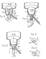
- the dispensing pump shown comprises a pumping chamber 10 comprising a cylindrical side wall 11 and a bottom end wall 12.
- the chamber 10 is integral with a container 13 which holds a quantity of a free-flowing liquid to be dispensed. When empty, the container and pump are discarded.
- a guide tube 14 integral with the chamber 10 opens axially out of the end wall 12 and has an outlet 15 in the wall thereof leading to a delivery nozzle 16.
- a piston rod 17 is axially slidable in the guide tube 14 and a piston 18 is mounted on the inner end of the piston rod within the chamber 10.
- the piston rod 17 is adapted to make a fluid-tight seal with the wall of the guide tube 14 and for this purpose an 0-ring seal 19 is fitted to the rod.
- the piston rod 17 projects downwardly beyond the lower end of the guide tube and is adapted to be connected to a suitable means (not shown) for reciprocating the piston rod 17 and piston 18.
- An elongate portion 17a of the piston rod 17 between the seal 19 and the piston 18 has a smaller diameter and thus a lesser cross-sectional area than the remainder of the piston rod.
- Figure 1 shows the piston and piston rod in their inner or non-operated position wherein the piston 18 projects clear of the side wall 11 of the pumping chamber so that liquid in the container 13 can flow freely into the chamber 10 through the gap 20 between the piston 18 and the side wall 11.
- the piston rod seal 19 sealingly engages the wall of the guide tube 14 adjacent the end wall 12 of the chamber.
- the axial distance 21 between the upper edge of the outlet 15 in the guide tube 14 and the upper edge of the chamber side wall 11 is substantially the same as the axial distance 22 between the piston 18 and the seal 19 on the piston rod 17.
- the reciprocating means (not shown) are operated to draw the piston rod 17 and piston 18 downwardly as a unit. A short while after the commencement of the delivery stroke, the piston 18 moves into sealing engagement with the side wall 11 of the pumping chamber, so trapping the liquid within the chamber. At this instant, Figure 2, the seal 19 .on the rod 17 is just clearing the upper edge of the outlet 15. Continuing movement of the rod and piston pumps the liquid from the interior of the pumping chamber 10 out through the outlet 15 and the nozzle 16, Figure 3. The liquid flows out of the chamber 10 through the annular passage 23 which is formed between the guide tube 14 and the rod portion 17a which is of reduced cross-sectional area, to the delivery opening 15.
- Figure 4 shows the piston 18 and rod 17 in the outer position at the conclusion of the delivery stroke.
- Means may be provided for varying the length of the delivery stroke by altering the outer position within a range of outer positions for selecting the quantity of substance disposed at each pumping stroke, as will be apparent to those skilled in the art.
- Figure 5 shows the pump after the piston 18 and rod 17 have moved a short distance through its return stroke.
- the initial effect of the return movement is to draw back into the pumping chamber 10 and the annular passage 23 any substance remaining in the nozzle 16 and not ejected. This means that there is both instant cut-off of delivery and positive prevention of drips.
- the volume of the pumping chamber 10 not occupied by liquid drawn back then fills with air drawn in through the delivery duct 16.
- the container 13 can therefore be completely closed and can be rigid or flexible. If rigid, only a thin wall is needed.
- the pump can be modified as shown in Figure 7.
- the container 13a is flexible and the nozzle 16 includes a self-sealing non-return valve 24 at its outlet end.
- the piston 18a is made so that it is sufficiently rigid to maintain sealing engagement with the side wall 11 of the pumping chamber 10 during the pumping stroke reliably to expel substance from the chamber, but so that it can flex out of sealing contact with the side wall 11 of the chamber during the return stroke.
- the embodiment performs a pumping stroke as already described. As shown in Figure 7, immediately the piston 18a begins the return stroke the non-return valve 24 closes and a vacuum is created within the pumping chamber 10 which increases as the return stroke progresses. Substance from the container 13a is therefore positively drawn into the chamber 10, the flexing of the piston 18a away from the side wall 11 assisting the flow of substance into the chamber.
- FIG. 8 to 11 Another embodiment of pump for dispensing a viscous fluent substance is shown in Figures 8 to 11.
- a separate non-return valve 24 is not required, the function of such valve being performed by the piston rod.
- the piston rod 117 in the embodiment of Figures 8 to 11 is formed so as to act as a non-return valve during the return stroke.
- the cross-sectional area of the portion 117a is reduced by relieving the portion 117a asymmetrically over a circumferential region less than 360° so as to leave a face 124 of the rod of sufficient angular extent to act as a non-return valve by obturating the outlet 15 when such face 124 is angularly aligned with the opening 15.
- the piston rod 117 is drawn downwards in such rotational position that the face 124 is not aligned with the outlet 15 and substance is dispensed from the nozzle 16 to which it flows through the space 123 between portion 117a and the guide tube 14, and the delivery opening 15, Figures 9 and 11.
- the piston rod 17 is rotated to align the face 124 with the outlet 15, Figures 10 and 12.
- the outlet is therefore obturated and a vacuum is created in the pumping chamber 10, as in the embodiment of Figure 7, so that substance from the container is positively forced into the chamber either round the edge of a flexing piston 18a, or rushes in through the gap 20 when a rigid piston 18 clears the end of the side wall 11.
- the piston 18 is rotated in the opposite direction to assume its aforementioned rotational position for dispensing.
- means for reciprocating the piston rod can be arranged also to rotate the piston rod at the appropriate points.
- the container should either be collapsible or include a fol1ower,eithar weighted or non-weighted pressing down on the contents.
- the pump may, of course, also be used to dispense liquids, in which case the piston rod need not be rotated.
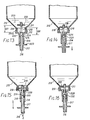
- FIG. 13 A preferred embodiment of pump of the invention particularly for dispensing free-flowing liquids is shown in Figures 13 to 18.
- the pump shown comprises a pumping chamber 210 having a cylindrical side wall 211 and a bottom end wall 212.
- the chamber 210 has an external annular flange 210a which is swaged over the mouth of a blow moulded container 213 which holds a quantity of a free-flowing liquid to be dispensed.
- a guide tube 214 integral with the chamber 210 opens axially out of the end wall 212.
- a piston rod 217 is axially slidable in the guide tube 214 and a piston 218 is mounted on the inner end of the piston rod within the chamber 210.
- the piston rod 217 comprises three sections namely an inner end section 219, a sealing plug 220 and a tubular outer section 221.
- Inner end section 219 is solid and has a smaller diameter than sections 220 and 221.
- the piston 218 may be a snap- fit on the end section 219.
- the plug 220 has a diameter intermediate those of the sections 219 and 221.
- the piston rod 217 is formed with a transverse outlet bore 215 which communicates with the interior of the hollow outer section 221 and provides a delivery nozzle 216 on the outer end of the piston rod.
- An 0-ring seal (not shown) may be fitted around the outer section 221 of the piston rod to make a fluid-tight seal between the rod and the wall of the guide tube 214.
- the piston rod 217 projects downwardly beyond the lower end of the guide tube and is provided with an annular rib 223 adapted to be connected to a suitable means (not shown) for reciprocating the piston rod 217 and piston 218.
- the plug 220 has a smaller diameter and thus a lesser cross-sectional area than the outer section 221 of the piston rod and is preferably tapered upwardly in a wedging shape.
- the guide tube 214 adjacent the end wall 212 has a section 224 of reduced internal diameter with which the plug 220 is adapted to mate and seal.
- Figure 13 shows the piston and piston rod in their inner or.non-operated position wherein the piston 218 projects clear of the side wall 211 of the pumping chamber so that liquid in the container 213 can flow freely into the chamber 210 through the gap 225 between the piston 218 and the side wall 211.
- the plug 220 is sealingly engaged with the guide tube section 224 so that the chamber 210 is effectively sealed at its bottom.
- the axial distance 226 between the lower edge of the section 224 of the guide tube 214 and the upper edge of the chamber side wall 211 is substantially the same as the axial distance 227 between the piston 218 and the upper end of the plug.
- the reciprocating means (not shown) are operated to draw the piston rod 217 and piston 218 downwardly as a unit.
- the piston 218 moves into sealing engagement with the side wall 211 of the pumping chamber, so trapping the liquid within the chamber.
- the plug section 220 is just clearing the lower edge of the section 224 of the guide tube.
- a maximum quantity of liquid is discharged.
- means may be provided for varying the length of the delivery stroke by altering the outer position within a range of outer positions for selecting the quantity of substance disposed at each pumping stroke.
- Figure 16 shows the pump after the piston 218 and rod 217 have moved a short distance through its return stroke.
- the initial effect of the return movement is to draw back into the pumping chamber 210 and the passage 228 any substance remaining in the outlet 215 and not delivered through the nozzle 216. This means that there is both instant cut-off of delivery and positive prevention of drips.
- the volume of the pumping chamber 210 not occupied by liquid drawn back then fills with air drawn in through the nozzle 216.
- the entire pump as described may be manufactured very simply and cheaply by moulding in suitable plastic material.
- the pump essentially comprises only one moving part, namely, the unit consisting of the piston rod and the piston.
- the only parts in continuous contact with the fluent substance are the inner end of the piston rod, the piston and the sealing members which can readily be made of a corrosion resistant plastic, the wiping or wedging action of the sealing members ensuring the creation of a reliable seal not subject to deterioration.
- the low cost of the pump enables the pump to be fitted and sold integral with the container as a disposable dispensing pack.
Landscapes
- Physics & Mathematics (AREA)
- Fluid Mechanics (AREA)
- General Physics & Mathematics (AREA)
- Reciprocating Pumps (AREA)
- Closures For Containers (AREA)
- Containers And Packaging Bodies Having A Special Means To Remove Contents (AREA)
- Nitrogen And Oxygen Or Sulfur-Condensed Heterocyclic Ring Systems (AREA)
Priority Applications (1)
| Application Number | Priority Date | Filing Date | Title |
|---|---|---|---|
| AT79302395T ATE2762T1 (de) | 1978-11-01 | 1979-10-31 | Verteilerpumpe. |
Applications Claiming Priority (4)
| Application Number | Priority Date | Filing Date | Title |
|---|---|---|---|
| GB4271778 | 1978-11-01 | ||
| GB7842717 | 1978-11-01 | ||
| GB7903111 | 1979-01-30 | ||
| GB7903111 | 1979-01-30 |
Publications (2)
| Publication Number | Publication Date |
|---|---|
| EP0010963A1 true EP0010963A1 (fr) | 1980-05-14 |
| EP0010963B1 EP0010963B1 (fr) | 1983-03-09 |
Family
ID=26269414
Family Applications (1)
| Application Number | Title | Priority Date | Filing Date |
|---|---|---|---|
| EP79302395A Expired EP0010963B1 (fr) | 1978-11-01 | 1979-10-31 | Pompe distributrice |
Country Status (6)
| Country | Link |
|---|---|
| EP (1) | EP0010963B1 (fr) |
| DE (1) | DE2965002D1 (fr) |
| DK (1) | DK146933C (fr) |
| FI (1) | FI65128C (fr) |
| IE (1) | IE48868B1 (fr) |
| NO (1) | NO149594C (fr) |
Cited By (8)
| Publication number | Priority date | Publication date | Assignee | Title |
|---|---|---|---|---|
| FR2541244A1 (fr) * | 1983-02-17 | 1984-08-24 | Oreal | Dispositif distributeur de doses de substance liquide |
| WO1989007244A1 (fr) * | 1988-02-05 | 1989-08-10 | Stella Kg Werner Deussen | Distributeur-doseur de fluides, notamment de medicaments fluides contenus dans des recipients |
| WO1991004465A1 (fr) * | 1989-09-22 | 1991-04-04 | The Coca-Cola Company | Systeme et procede de dosage |
| US5154319A (en) * | 1989-09-22 | 1992-10-13 | The Coca-Cola Company | Apparatus for the dispensing of liquids in measured amounts |
| US5234134A (en) * | 1989-09-22 | 1993-08-10 | The Coca-Cola Company | Device for the measured dispensing of liquids out of a storage container |
| AU641180B2 (en) * | 1989-09-22 | 1993-09-16 | Bosch-Siemens Hausgerate Gmbh | Apparatus for dispensing liquid in measured amounts |
| FR2692040A1 (fr) * | 1992-06-04 | 1993-12-10 | Valois | Dispositif doseur pour substance fluide. |
| US7497359B2 (en) | 2002-02-07 | 2009-03-03 | 3M Innovative Properties Company | Dosing device |
Families Citing this family (2)
| Publication number | Priority date | Publication date | Assignee | Title |
|---|---|---|---|---|
| DE3910066C2 (de) * | 1988-08-18 | 1997-10-02 | Thomas Peter | Vorrichtung zur Portionierung und Abgabe von fließfähigen Medien |
| DE3912163A1 (de) * | 1988-10-21 | 1990-04-26 | Thomas Peter | Vorrichtung zur portionierung und abgabe von fluessigkeiten |
Citations (4)
| Publication number | Priority date | Publication date | Assignee | Title |
|---|---|---|---|---|
| FR577059A (fr) * | 1924-02-11 | 1924-08-30 | Bouchon doseur | |
| US2009743A (en) * | 1934-11-14 | 1935-07-30 | Edward K Morlok | Dispenser |
| US2511723A (en) * | 1948-02-25 | 1950-06-13 | Lester L Lewis | Dispenser closure for bottles |
| FR1416519A (fr) * | 1964-09-23 | 1965-11-05 | Cem Comp Electro Mec | Pompe à faible débit, du type à piston plongeur animé d'un mouvement de rotation |
-
1979
- 1979-10-30 DK DK458979A patent/DK146933C/da not_active IP Right Cessation
- 1979-10-31 FI FI793406A patent/FI65128C/fi not_active IP Right Cessation
- 1979-10-31 EP EP79302395A patent/EP0010963B1/fr not_active Expired
- 1979-10-31 DE DE7979302395T patent/DE2965002D1/de not_active Expired
- 1979-10-31 NO NO793506A patent/NO149594C/no unknown
- 1979-10-31 IE IE2094/79A patent/IE48868B1/en unknown
Patent Citations (4)
| Publication number | Priority date | Publication date | Assignee | Title |
|---|---|---|---|---|
| FR577059A (fr) * | 1924-02-11 | 1924-08-30 | Bouchon doseur | |
| US2009743A (en) * | 1934-11-14 | 1935-07-30 | Edward K Morlok | Dispenser |
| US2511723A (en) * | 1948-02-25 | 1950-06-13 | Lester L Lewis | Dispenser closure for bottles |
| FR1416519A (fr) * | 1964-09-23 | 1965-11-05 | Cem Comp Electro Mec | Pompe à faible débit, du type à piston plongeur animé d'un mouvement de rotation |
Cited By (11)
| Publication number | Priority date | Publication date | Assignee | Title |
|---|---|---|---|---|
| FR2541244A1 (fr) * | 1983-02-17 | 1984-08-24 | Oreal | Dispositif distributeur de doses de substance liquide |
| WO1989007244A1 (fr) * | 1988-02-05 | 1989-08-10 | Stella Kg Werner Deussen | Distributeur-doseur de fluides, notamment de medicaments fluides contenus dans des recipients |
| US5037007A (en) * | 1988-02-05 | 1991-08-06 | Stella Kg Werner Deussen | Device for dispensing a dosed amount of free-flowing material, in particular liquid medication from a container |
| WO1991004465A1 (fr) * | 1989-09-22 | 1991-04-04 | The Coca-Cola Company | Systeme et procede de dosage |
| US5058780A (en) * | 1989-09-22 | 1991-10-22 | The Coca-Cola Company | Dosing system for an unvented container |
| US5154319A (en) * | 1989-09-22 | 1992-10-13 | The Coca-Cola Company | Apparatus for the dispensing of liquids in measured amounts |
| AU634827B2 (en) * | 1989-09-22 | 1993-03-04 | Coca-Cola Company, The | Dosing system and method |
| US5234134A (en) * | 1989-09-22 | 1993-08-10 | The Coca-Cola Company | Device for the measured dispensing of liquids out of a storage container |
| AU641180B2 (en) * | 1989-09-22 | 1993-09-16 | Bosch-Siemens Hausgerate Gmbh | Apparatus for dispensing liquid in measured amounts |
| FR2692040A1 (fr) * | 1992-06-04 | 1993-12-10 | Valois | Dispositif doseur pour substance fluide. |
| US7497359B2 (en) | 2002-02-07 | 2009-03-03 | 3M Innovative Properties Company | Dosing device |
Also Published As
| Publication number | Publication date |
|---|---|
| DK146933C (da) | 1984-07-30 |
| NO149594C (no) | 1984-05-16 |
| NO149594B (no) | 1984-02-06 |
| FI793406A7 (fi) | 1980-05-02 |
| DE2965002D1 (en) | 1983-04-14 |
| EP0010963B1 (fr) | 1983-03-09 |
| IE792094L (en) | 1980-05-01 |
| NO793506L (no) | 1980-05-05 |
| FI65128B (fi) | 1983-11-30 |
| DK458979A (da) | 1980-05-02 |
| DK146933B (da) | 1984-02-20 |
| IE48868B1 (en) | 1985-06-12 |
| FI65128C (fi) | 1984-03-12 |
Similar Documents
| Publication | Publication Date | Title |
|---|---|---|
| US5363993A (en) | Plastic dispenser for liquids or other substances | |
| US6234363B1 (en) | Device for dispensing a fluid with closure system | |
| US4696415A (en) | Apparatus for dispensing products from a self-sealing dispenser | |
| US4776495A (en) | Disposable dispenser pump for products in liquid or paste form | |
| EP1388500B1 (fr) | Clapet de sortie pour pompe de distribution | |
| US5816453A (en) | Dispenser pump | |
| US4315582A (en) | Universal sequential dispensing pump system free of external check valves and having venting capability | |
| US6240979B1 (en) | Dispenser, and method of filling the same | |
| PL200833B1 (pl) | Dozownik z pojemnikiem aplikowanego środka oraz pompka do dozownika | |
| JPH0299022A (ja) | 流体の押上式デイスペンサー | |
| EP0010963A1 (fr) | Pompe distributrice | |
| US5680966A (en) | Squeeze dispenser having refill cartridge | |
| JP2001080686A (ja) | 流動性媒体のディスペンサ | |
| HU217500B (hu) | Ujjheggyel működtetett, szelep nélküli szivattyús porlasztó | |
| CN100500524C (zh) | 具有气密喷口的分配器 | |
| US4674659A (en) | Universal sequential dispensing pump system | |
| US5395032A (en) | Dispenser for media | |
| EP0011487B1 (fr) | Appareil distributeur de substances visqueuses telles que pâtes ou crémes | |
| US7178701B2 (en) | Metering pump | |
| GB2111132A (en) | Dispenser pump | |
| HK1092438B (en) | Dispenser having air tight spout | |
| EP2117396A2 (fr) | Distributeur | |
| HK1021724B (en) | Fluid pump dispenser | |
| WO1998004494A1 (fr) | Distributeur de liquide | |
| HK1021724A1 (en) | Fluid pump dispenser |
Legal Events
| Date | Code | Title | Description |
|---|---|---|---|
| PUAI | Public reference made under article 153(3) epc to a published international application that has entered the european phase |
Free format text: ORIGINAL CODE: 0009012 |
|
| AK | Designated contracting states |
Designated state(s): AT BE CH DE FR GB IT LU NL SE |
|
| 17P | Request for examination filed |
Effective date: 19801020 |
|
| ITF | It: translation for a ep patent filed | ||
| GRAA | (expected) grant |
Free format text: ORIGINAL CODE: 0009210 |
|
| AK | Designated contracting states |
Designated state(s): AT BE CH DE FR GB IT LU NL SE |
|
| REF | Corresponds to: |
Ref document number: 2762 Country of ref document: AT Date of ref document: 19830315 Kind code of ref document: T |
|
| REF | Corresponds to: |
Ref document number: 2965002 Country of ref document: DE Date of ref document: 19830414 |
|
| ET | Fr: translation filed | ||
| PGFP | Annual fee paid to national office [announced via postgrant information from national office to epo] |
Ref country code: LU Payment date: 19830921 Year of fee payment: 5 |
|
| PG25 | Lapsed in a contracting state [announced via postgrant information from national office to epo] |
Ref country code: LU Free format text: LAPSE BECAUSE OF NON-PAYMENT OF DUE FEES Effective date: 19831031 |
|
| PGFP | Annual fee paid to national office [announced via postgrant information from national office to epo] |
Ref country code: CH Payment date: 19841009 Year of fee payment: 6 |
|
| PGFP | Annual fee paid to national office [announced via postgrant information from national office to epo] |
Ref country code: FR Payment date: 19841026 Year of fee payment: 6 |
|
| PGFP | Annual fee paid to national office [announced via postgrant information from national office to epo] |
Ref country code: DE Payment date: 19841029 Year of fee payment: 6 |
|
| PGFP | Annual fee paid to national office [announced via postgrant information from national office to epo] |
Ref country code: SE Payment date: 19841231 Year of fee payment: 6 Ref country code: BE Payment date: 19841231 Year of fee payment: 6 |
|
| PGFP | Annual fee paid to national office [announced via postgrant information from national office to epo] |
Ref country code: AT Payment date: 19851029 Year of fee payment: 7 |
|
| PGFP | Annual fee paid to national office [announced via postgrant information from national office to epo] |
Ref country code: NL Payment date: 19851031 Year of fee payment: 7 |
|
| PG25 | Lapsed in a contracting state [announced via postgrant information from national office to epo] |
Ref country code: CH Effective date: 19861031 Ref country code: BE Effective date: 19861031 Ref country code: AT Effective date: 19861031 |
|
| BERE | Be: lapsed |
Owner name: STERWIN A.G. Effective date: 19861031 |
|
| PG25 | Lapsed in a contracting state [announced via postgrant information from national office to epo] |
Ref country code: NL Effective date: 19870501 |
|
| NLV4 | Nl: lapsed or anulled due to non-payment of the annual fee | ||
| PG25 | Lapsed in a contracting state [announced via postgrant information from national office to epo] |
Ref country code: FR Free format text: LAPSE BECAUSE OF NON-PAYMENT OF DUE FEES Effective date: 19870630 |
|
| REG | Reference to a national code |
Ref country code: CH Ref legal event code: PL |
|
| PG25 | Lapsed in a contracting state [announced via postgrant information from national office to epo] |
Ref country code: DE Effective date: 19870701 |
|
| REG | Reference to a national code |
Ref country code: FR Ref legal event code: ST |
|
| PG25 | Lapsed in a contracting state [announced via postgrant information from national office to epo] |
Ref country code: SE Effective date: 19891101 |
|
| PGFP | Annual fee paid to national office [announced via postgrant information from national office to epo] |
Ref country code: GB Payment date: 19940928 Year of fee payment: 16 |
|
| EUG | Se: european patent has lapsed |
Ref document number: 79302395.3 Effective date: 19900705 |
|
| PG25 | Lapsed in a contracting state [announced via postgrant information from national office to epo] |
Ref country code: GB Effective date: 19951031 |
|
| GBPC | Gb: european patent ceased through non-payment of renewal fee |
Effective date: 19951031 |
|
| PLBE | No opposition filed within time limit |
Free format text: ORIGINAL CODE: 0009261 |
|
| STAA | Information on the status of an ep patent application or granted ep patent |
Free format text: STATUS: NO OPPOSITION FILED WITHIN TIME LIMIT |