EP0011076A2 - Dispositif support de feuilles - Google Patents
Dispositif support de feuilles Download PDFInfo
- Publication number
- EP0011076A2 EP0011076A2 EP79100239A EP79100239A EP0011076A2 EP 0011076 A2 EP0011076 A2 EP 0011076A2 EP 79100239 A EP79100239 A EP 79100239A EP 79100239 A EP79100239 A EP 79100239A EP 0011076 A2 EP0011076 A2 EP 0011076A2
- Authority
- EP
- European Patent Office
- Prior art keywords
- sheet
- support elements
- arch support
- drum
- arch
- Prior art date
- Legal status (The legal status is an assumption and is not a legal conclusion. Google has not performed a legal analysis and makes no representation as to the accuracy of the status listed.)
- Granted
Links
Images

Classifications
-
- B—PERFORMING OPERATIONS; TRANSPORTING
- B41—PRINTING; LINING MACHINES; TYPEWRITERS; STAMPS
- B41F—PRINTING MACHINES OR PRESSES
- B41F22/00—Means preventing smudging of machine parts or printed articles
Definitions
- the invention relates to a sheet support device, which is arranged axially and radially adjustable on a transfer drum of multicolor rotary printing presses, with carriers running in the circumferential direction on the drum jacket, on which the sheet support elements are interchangeably and displaceably attached in the circumferential direction, the sheet being in the working position of the sheet support elements rests on the supporting edge.
- the printed sheet is transported between the individual printing units by means of transfer drums.
- the freshly printed side of the sheet can come to rest on the outer surface of the transfer drum, as a result of which the printed image can be damaged by smearing or smearing of the wet ink.
- a known embodiment of this type uses a wire as a support for the arch support elements, on which they are attached.
- the arch support elements are slotted in the longitudinal direction.
- the individual sheet support elements are displaceable on the wire in the circumferential direction of the transfer drum, and the wire with the elements is displaceable in the axial direction of the drum.
- the disadvantage of the known design is that the adjustment of the sheet support elements to unprinted locations on the sheet to be transferred is complex and complicated. With each setting, either arch support elements must be plugged onto or removed from the wires, the arch support elements having to be stored outside the machine and can also be lost.
- the wires have no side guide and are therefore very difficult to move laterally. Virtually every element must be moved individually and aligned sideways.
- the object of the invention is to provide an inexpensive adjustable sheet support device on transfer drums which does not require any additional storage space for the sheet support elements and is easily adjustable to pressure-free locations.
- the arch-carrying ducks are threaded over bores on ropes which have at least one end with a hook with which they are hooked onto the drum jacket, and that the arch-supporting elements have a square cross section with a center to the bore have protruding support edge and are arranged on a guide belt which can be folded over at right angles, which in turn can be displaced in the axial direction on the outer surface of the transfer drum.
- This has created a sheet-carrying device which is simple and safe to use and which can be easily adjusted to all printing work occurring in practice. Due to the square cross-section of the arch support elements, they can easily be folded down from the working position to the rest position.
- the guide strip on its outer periphery a recess, which in their width corresponding to an edge of the square cross section of the sheet supporting members so that the sheet supporting elements with the square cross-section engage in the recess with a folding 90 0th
- the sheet support elements have a clamping opening with which they are attached to brackets which form a segment of a circle and are displaceable in the axial direction thereof on a guide rod fastened in the transfer drum.
- the arch support element is designed as a spring steel element and encloses an approximately square opening, wherein it is attached to a bracket with a square cross section.
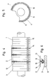
- the transfer drum 1 is in a known manner with a Darge provided gripper device, by means of which it takes over the sheet 2 to be transported from the previous grippers and delivers it to the next gripper of a transfer drum or a printing cylinder.
- the sheet 2 which can have different lengths and widths, lies on the sheet support elements 6 on the drum jacket 3.
- Spring-elastic cables 4 are tensioned on the drum jacket 3 in the circumferential direction, onto which individual bow support elements 6 having a bore 5 are threaded (FIGS. 1 to 3).
- the arch support elements 6 are provided with a supporting edge 7 on which the arch 2 is deposited.
- the sheet support member 6 can be folded from a central, vertical working position on both sides into a rest position (shown in dash-dotted lines). Due to the square cross section of the arch support element, centered on the bore 7, the same engages in any position.
- each rope 4 has hooks 8 at the ends with which it is hooked onto the drum jacket 9.
- the sheet support elements 6 are arranged on a guide belt 10 (FIGS. 1 and 3), which in turn is displaceable on the lateral surface 3 of the transfer drum 1 in the axial direction thereof.
- the guide band 10 is held in place by the rope 4 on the drum shell.
- the guide band 10 has on its outer periphery a recess 11, the width of an edge of the square cross section of the Bogentrageleme nte 6, so that the arch support elements with the square cross section when folded by 90 ° in engage the recess 11.
- the arch support element 12 is designed as a spring steel element and encloses an approximately square opening 13. With this opening 13, it is attached to a bracket 14 with a square cross section and also has a supporting edge 15 Edition of sheet 2 on.
- the bracket 14 is mounted on a guide rod 16 fastened in the transfer drum 1 so that it can be displaced in the axial direction thereof. In addition, it is supported by supports 17 on the drum jacket 9.
Landscapes
- Feeding Of Articles By Means Other Than Belts Or Rollers (AREA)
- Supply, Installation And Extraction Of Printed Sheets Or Plates (AREA)
- Electrostatic Charge, Transfer And Separation In Electrography (AREA)
- Handling Of Cut Paper (AREA)
Applications Claiming Priority (2)
| Application Number | Priority Date | Filing Date | Title |
|---|---|---|---|
| DE2813136A DE2813136C3 (de) | 1978-03-25 | 1978-03-25 | Bogentrageinrichtung, die axial und in Umfangsrichtung verstellbar auf einer Überführtrommel angeordnet ist |
| DE2813136 | 1978-03-25 |
Publications (3)
| Publication Number | Publication Date |
|---|---|
| EP0011076A2 true EP0011076A2 (fr) | 1980-05-28 |
| EP0011076A3 EP0011076A3 (en) | 1980-06-25 |
| EP0011076B1 EP0011076B1 (fr) | 1982-06-09 |
Family
ID=6035464
Family Applications (1)
| Application Number | Title | Priority Date | Filing Date |
|---|---|---|---|
| EP79100239A Expired EP0011076B1 (fr) | 1978-03-25 | 1979-01-29 | Dispositif support de feuilles |
Country Status (12)
| Country | Link |
|---|---|
| US (1) | US4242959A (fr) |
| EP (1) | EP0011076B1 (fr) |
| JP (1) | JPS54131404A (fr) |
| AR (1) | AR221870A1 (fr) |
| AT (1) | AT374739B (fr) |
| AU (1) | AU524936B2 (fr) |
| BR (1) | BR7901791A (fr) |
| CA (1) | CA1126082A (fr) |
| DE (1) | DE2813136C3 (fr) |
| DK (1) | DK146378C (fr) |
| ES (1) | ES478436A1 (fr) |
| ZA (1) | ZA791199B (fr) |
Cited By (2)
| Publication number | Priority date | Publication date | Assignee | Title |
|---|---|---|---|---|
| EP0146687A1 (fr) * | 1983-11-25 | 1985-07-03 | M.A.N.-ROLAND Druckmaschinen Aktiengesellschaft | Machines de manutention de feuilles |
| GB2278106A (en) * | 1993-05-10 | 1994-11-23 | Heidelberger Druckmasch Ag | Sheet-size ajustment of a printing press sheet-transfer drum |
Families Citing this family (15)
| Publication number | Priority date | Publication date | Assignee | Title |
|---|---|---|---|---|
| US5009160A (en) * | 1987-06-05 | 1991-04-23 | Eduardo Duarte | Transfer cylinder for printing press |
| US4967661A (en) * | 1987-06-05 | 1990-11-06 | Duarte Procuts, Inc. | Sheet transfer mechanism for printing press |
| DE3929228A1 (de) * | 1989-09-02 | 1991-03-21 | Koenig & Bauer Ag | Ueberfuehrtrommel |
| JP3730359B2 (ja) * | 1997-04-24 | 2006-01-05 | 株式会社小森コーポレーション | 反転機構付き枚葉輪転印刷機 |
| DE102004009703A1 (de) * | 2004-02-27 | 2005-09-15 | Heidelberger Druckmaschinen Ag | Maschine zum Verarbeiten von Bogen aus Bedruckstoff |
| CN111683814B (zh) | 2017-10-13 | 2022-07-01 | 柯尼格及包尔公开股份有限公司 | 加工单张纸的机器和传送单张纸的方法 |
| DE102017218412A1 (de) | 2017-10-13 | 2019-04-18 | Koenig & Bauer Ag | Bogentransportvorrichtung und Verfahren zum Transportieren von Bogen von einem Bogenführungszylinder an ein Bogenfördersystem |
| DE102017218410B4 (de) | 2017-10-13 | 2021-06-17 | Koenig & Bauer Ag | Bogentransportvorrichtung und Verfahren zum Transportieren von Bogen von einem Bogenführungszylinder an ein Bogenfördersystem |
| DE102017012198B9 (de) | 2017-10-13 | 2022-10-06 | Koenig & Bauer Ag | Bogentransportvorrichtung und Verfahren zum Transportieren von Bogen von einem Bogenführungszylinder an ein Bogenfördersystem |
| DE102017218411B4 (de) | 2017-10-13 | 2021-06-10 | Koenig & Bauer Ag | Bogentransportvorrichtung und Verfahren zum Transportieren von Bogen von einem Bogenführungszylinder an ein Bogenfördersystem |
| DE102017218413B4 (de) | 2017-10-13 | 2025-02-27 | Koenig & Bauer Ag | Bogentransportvorrichtung und Verfahren zum Transportieren von Bogen von einem Bogenführungszylinder an ein Bogenfördersystem |
| DE102017218407B4 (de) | 2017-10-13 | 2021-06-17 | Koenig & Bauer Ag | Bogentransportvorrichtung und Verfahren zum Transportieren von Bogen von einem Bogenführungszylinder an ein Bogenfördersystem |
| DE102017218409A1 (de) | 2017-10-13 | 2019-04-18 | Koenig & Bauer Ag | Bogentransportvorrichtung und Verfahren zum Transportieren von Bogen von einem Bogenführungszylinder an ein Bogenfördersystem |
| EP3694718B1 (fr) | 2017-10-13 | 2021-12-01 | Koenig & Bauer AG | Machine de traitement de feuilles dotée d'un dispositif de transport de feuilles et procédé de transport de feuilles d'un cylindre de guidage de feuilles vers un système de transport de feuilles |
| CN111315581B (zh) | 2017-10-13 | 2022-03-11 | 柯尼格及包尔公开股份有限公司 | 加工单张纸的机器和用于由单张纸引导滚筒将单张纸传送给单张纸给送系统的方法 |
Family Cites Families (6)
| Publication number | Priority date | Publication date | Assignee | Title |
|---|---|---|---|---|
| DE7303778U (de) * | 1973-04-26 | Maschinenfabrik Augsburg Nuernberg Ag | Ubergabetrommel fur Rotations Bogendruckmaschinen | |
| CH392564A (de) * | 1961-09-26 | 1965-05-31 | Color Metal Ag | Umführtrommel für Rotationsdruckmaschinen |
| DE1179559B (de) * | 1963-06-05 | 1964-10-15 | Roland Offsetmaschf | Auslegertrommel |
| US3442506A (en) * | 1967-06-30 | 1969-05-06 | Miehle Goss Dexter Inc | Antismudge sheet transfer device |
| US3643598A (en) * | 1969-01-23 | 1972-02-22 | Nebiolo Spa | Sheet transfer roller for use in multicolor rotary printing presses |
| DE2025849B2 (de) * | 1970-05-27 | 1973-10-31 | Maschinenfabrik Augsburg-Nuernberg Ag, 8900 Augsburg | Uberfuhrtrommel von Bogenrota tionsdruckmaschinen mit Vorrichtungen zum Verhindern des Abschmierens |
-
1978
- 1978-03-25 DE DE2813136A patent/DE2813136C3/de not_active Expired
-
1979
- 1979-01-29 EP EP79100239A patent/EP0011076B1/fr not_active Expired
- 1979-02-01 CA CA320,676A patent/CA1126082A/fr not_active Expired
- 1979-03-02 AR AR275683A patent/AR221870A1/es active
- 1979-03-02 AU AU44781/79A patent/AU524936B2/en not_active Ceased
- 1979-03-05 AT AT0166179A patent/AT374739B/de not_active IP Right Cessation
- 1979-03-08 ES ES478436A patent/ES478436A1/es not_active Expired
- 1979-03-14 ZA ZA791199A patent/ZA791199B/xx unknown
- 1979-03-20 JP JP3186879A patent/JPS54131404A/ja active Granted
- 1979-03-23 BR BR7901791A patent/BR7901791A/pt unknown
- 1979-03-23 DK DK121179A patent/DK146378C/da active
- 1979-03-26 US US06/024,011 patent/US4242959A/en not_active Expired - Lifetime
Cited By (4)
| Publication number | Priority date | Publication date | Assignee | Title |
|---|---|---|---|---|
| EP0146687A1 (fr) * | 1983-11-25 | 1985-07-03 | M.A.N.-ROLAND Druckmaschinen Aktiengesellschaft | Machines de manutention de feuilles |
| GB2278106A (en) * | 1993-05-10 | 1994-11-23 | Heidelberger Druckmasch Ag | Sheet-size ajustment of a printing press sheet-transfer drum |
| US5402723A (en) * | 1993-05-10 | 1995-04-04 | Heidelberger Druckmaschinen Ag | Device for sheet-format adjustment of a sheet-transfer drum |
| GB2278106B (en) * | 1993-05-10 | 1997-03-19 | Heidelberger Druckmasch Ag | Apparatus for the sheet-size adjustment of a sheet-transfer drum |
Also Published As
| Publication number | Publication date |
|---|---|
| ZA791199B (en) | 1980-03-26 |
| AR221870A1 (es) | 1981-03-31 |
| DE2813136B2 (de) | 1980-01-24 |
| ATA166179A (de) | 1983-10-15 |
| DE2813136C3 (de) | 1986-04-17 |
| US4242959A (en) | 1981-01-06 |
| EP0011076A3 (en) | 1980-06-25 |
| AT374739B (de) | 1984-05-25 |
| DK146378B (da) | 1983-09-26 |
| EP0011076B1 (fr) | 1982-06-09 |
| AU4478179A (en) | 1979-10-04 |
| ES478436A1 (es) | 1979-05-16 |
| CA1126082A (fr) | 1982-06-22 |
| JPS5614475B2 (fr) | 1981-04-04 |
| DK121179A (da) | 1979-09-26 |
| BR7901791A (pt) | 1979-11-20 |
| DK146378C (da) | 1984-03-26 |
| DE2813136A1 (de) | 1979-09-27 |
| JPS54131404A (en) | 1979-10-12 |
| AU524936B2 (en) | 1982-10-14 |
Similar Documents
| Publication | Publication Date | Title |
|---|---|---|
| EP0011076A2 (fr) | Dispositif support de feuilles | |
| DE2632243C3 (de) | Auf variable Bogenlängen einstellbare Umführtrommel für Druckmaschinen | |
| DE3535621C2 (fr) | ||
| DE4213024B4 (de) | Bogendruckmaschine | |
| DE1761714A1 (de) | Geraet zum UEbertragen von Druckbogen in Vielfarben-Druckpressen | |
| DE2002877B2 (de) | Bogenttbergabetrommel für Mehrfarben-Rotatlonsdruckmaschinen | |
| DE2804556C2 (de) | Abnehmbare Kanalabdeckung von Zylinderkanälen bei Druckmaschinen | |
| DE2518334C2 (de) | Bogentragscheibe fuer bogenueberfuehrungstrommeln | |
| DE7303778U (de) | Ubergabetrommel fur Rotations Bogendruckmaschinen | |
| DE960994C (de) | Bogen-Gummidruckmaschine fuer Schoen- und Widerdruck | |
| DE3819186A1 (de) | Verfahren und vorrichtung zum ueberfuehren eines frisch bedruckten bogens | |
| DE2713994A1 (de) | Bogenhaltevorrichtung einer bogen- rotations-druckmaschine, welche den druckbogen geringfuegig zu verformen vermag | |
| EP0561134A1 (fr) | Dispositif de tension d'un blanchet sur des cylindres de transfert pour machines à imprimer sur feuilles | |
| DE4427944C1 (de) | Vorrichtung zum Befestigen von biegsamen Platten mit abgekanteten Enden auf einem Zylinder einer Rotationsdruckmaschine | |
| DE2025849A1 (de) | Einrichtung an Überführtrommeln von Bogenrotationsdruckmaschinen zum Verhindern des Abschmierens | |
| DE2358223A1 (de) | Umfuehrtrommel mit einrichtungen zur erfassung der bogenvorder- und bogenhinterkante fuer druckmaschinen | |
| DE4420314C2 (de) | Vorrichtung zum Befestigen und Spannen von Druckplatten mit "Z"-förmig abgekanteten Enden | |
| DE4207795A1 (de) | Vorrichtung zum automatischen anbringen und entfernen von vorsatzeinrichtungen | |
| DE10103631A1 (de) | Rollenrotationsdruckmaschine | |
| DE2948489C2 (de) | Gummizylinder für eine Bogen-Offsetdruckmaschine | |
| DE2163417A1 (de) | Einrichtung zum befestigen des gummituches bzw. einer druckplatte auf dem gummi- oder plattenzylinder einer rotationsoffsetdruckmaschine | |
| EP0452722B1 (fr) | Machine de sérigraphie | |
| CH650976A5 (en) | Device for applying a liquid to the plate cylinder of a rotary printing machine | |
| DE2139831C3 (de) | Offset-Bogenrotationsdruckm aschine | |
| DE1800257B1 (de) | UEberfuehrtrommel fuer Bogen-Rotationsdruckmaschinen in Reihenbauart |
Legal Events
| Date | Code | Title | Description |
|---|---|---|---|
| PUAI | Public reference made under article 153(3) epc to a published international application that has entered the european phase |
Free format text: ORIGINAL CODE: 0009012 |
|
| PUAL | Search report despatched |
Free format text: ORIGINAL CODE: 0009013 |
|
| AK | Designated contracting states |
Designated state(s): CH FR GB IT NL SE |
|
| AK | Designated contracting states |
Designated state(s): CH FR GB IT NL SE |
|
| 17P | Request for examination filed | ||
| ITF | It: translation for a ep patent filed | ||
| GRAA | (expected) grant |
Free format text: ORIGINAL CODE: 0009210 |
|
| AK | Designated contracting states |
Designated state(s): CH FR GB IT NL SE |
|
| PGFP | Annual fee paid to national office [announced via postgrant information from national office to epo] |
Ref country code: CH Payment date: 19821216 Year of fee payment: 5 |
|
| PGFP | Annual fee paid to national office [announced via postgrant information from national office to epo] |
Ref country code: FR Payment date: 19821229 Year of fee payment: 5 |
|
| PG25 | Lapsed in a contracting state [announced via postgrant information from national office to epo] |
Ref country code: CH Effective date: 19840131 |
|
| PG25 | Lapsed in a contracting state [announced via postgrant information from national office to epo] |
Ref country code: FR Free format text: LAPSE BECAUSE OF NON-PAYMENT OF DUE FEES Effective date: 19840928 |
|
| REG | Reference to a national code |
Ref country code: CH Ref legal event code: PL |
|
| REG | Reference to a national code |
Ref country code: FR Ref legal event code: ST |
|
| PGFP | Annual fee paid to national office [announced via postgrant information from national office to epo] |
Ref country code: SE Payment date: 19841231 Year of fee payment: 7 |
|
| PGFP | Annual fee paid to national office [announced via postgrant information from national office to epo] |
Ref country code: NL Payment date: 19860131 Year of fee payment: 8 |
|
| PG25 | Lapsed in a contracting state [announced via postgrant information from national office to epo] |
Ref country code: SE Effective date: 19870130 |
|
| PG25 | Lapsed in a contracting state [announced via postgrant information from national office to epo] |
Ref country code: NL Effective date: 19870801 |
|
| GBPC | Gb: european patent ceased through non-payment of renewal fee | ||
| NLV4 | Nl: lapsed or anulled due to non-payment of the annual fee | ||
| PG25 | Lapsed in a contracting state [announced via postgrant information from national office to epo] |
Ref country code: GB Effective date: 19881118 |
|
| EUG | Se: european patent has lapsed |
Ref document number: 79100239.7 Effective date: 19870917 |
|
| PLBE | No opposition filed within time limit |
Free format text: ORIGINAL CODE: 0009261 |
|
| STAA | Information on the status of an ep patent application or granted ep patent |
Free format text: STATUS: NO OPPOSITION FILED WITHIN TIME LIMIT |