EP0011360A1 - Dispositif servant au mélange du carburant et de l'air dans les moteurs à explosion - Google Patents
Dispositif servant au mélange du carburant et de l'air dans les moteurs à explosion Download PDFInfo
- Publication number
- EP0011360A1 EP0011360A1 EP79301982A EP79301982A EP0011360A1 EP 0011360 A1 EP0011360 A1 EP 0011360A1 EP 79301982 A EP79301982 A EP 79301982A EP 79301982 A EP79301982 A EP 79301982A EP 0011360 A1 EP0011360 A1 EP 0011360A1
- Authority
- EP
- European Patent Office
- Prior art keywords
- flow
- fuel
- air
- vortex
- outlet
- Prior art date
- Legal status (The legal status is an assumption and is not a legal conclusion. Google has not performed a legal analysis and makes no representation as to the accuracy of the status listed.)
- Granted
Links
- 239000000446 fuel Substances 0.000 title claims abstract description 267
- 238000002156 mixing Methods 0.000 title claims description 204
- 239000007788 liquid Substances 0.000 claims abstract description 52
- 239000000203 mixture Substances 0.000 claims description 94
- 230000002093 peripheral effect Effects 0.000 claims description 84
- 239000012530 fluid Substances 0.000 claims description 69
- 238000001704 evaporation Methods 0.000 claims description 48
- 238000002485 combustion reaction Methods 0.000 claims description 44
- 230000008020 evaporation Effects 0.000 claims description 41
- 230000006870 function Effects 0.000 claims description 40
- 230000000694 effects Effects 0.000 claims description 35
- 238000009826 distribution Methods 0.000 claims description 32
- 238000010438 heat treatment Methods 0.000 claims description 22
- 230000003071 parasitic effect Effects 0.000 claims description 22
- 230000003993 interaction Effects 0.000 claims description 20
- 239000007789 gas Substances 0.000 claims description 18
- 230000008016 vaporization Effects 0.000 claims description 15
- 230000007704 transition Effects 0.000 claims description 11
- 230000007480 spreading Effects 0.000 claims description 6
- 238000003892 spreading Methods 0.000 claims description 6
- 238000009833 condensation Methods 0.000 claims description 5
- 238000005260 corrosion Methods 0.000 claims description 4
- 230000007797 corrosion Effects 0.000 claims description 4
- 238000007493 shaping process Methods 0.000 claims description 3
- 229910052782 aluminium Inorganic materials 0.000 claims description 2
- XAGFODPZIPBFFR-UHFFFAOYSA-N aluminium Chemical compound [Al] XAGFODPZIPBFFR-UHFFFAOYSA-N 0.000 claims description 2
- 239000000463 material Substances 0.000 claims description 2
- 229960001948 caffeine Drugs 0.000 claims 1
- 230000003647 oxidation Effects 0.000 claims 1
- 238000007254 oxidation reaction Methods 0.000 claims 1
- 230000001681 protective effect Effects 0.000 claims 1
- RYYVLZVUVIJVGH-UHFFFAOYSA-N trimethylxanthine Natural products CN1C(=O)N(C)C(=O)C2=C1N=CN2C RYYVLZVUVIJVGH-UHFFFAOYSA-N 0.000 claims 1
- XLYOFNOQVPJJNP-UHFFFAOYSA-N water Substances O XLYOFNOQVPJJNP-UHFFFAOYSA-N 0.000 description 34
- 238000000034 method Methods 0.000 description 26
- 238000013461 design Methods 0.000 description 25
- 230000008569 process Effects 0.000 description 24
- 238000009792 diffusion process Methods 0.000 description 17
- 230000008901 benefit Effects 0.000 description 16
- 230000001052 transient effect Effects 0.000 description 14
- 238000012546 transfer Methods 0.000 description 13
- 230000004044 response Effects 0.000 description 11
- 238000004519 manufacturing process Methods 0.000 description 10
- 238000011161 development Methods 0.000 description 9
- 238000004821 distillation Methods 0.000 description 9
- GQPLMRYTRLFLPF-UHFFFAOYSA-N Nitrous Oxide Chemical compound [O-][N+]#N GQPLMRYTRLFLPF-UHFFFAOYSA-N 0.000 description 8
- ATUOYWHBWRKTHZ-UHFFFAOYSA-N Propane Chemical compound CCC ATUOYWHBWRKTHZ-UHFFFAOYSA-N 0.000 description 8
- 230000006872 improvement Effects 0.000 description 8
- 238000011160 research Methods 0.000 description 8
- 239000000523 sample Substances 0.000 description 8
- 238000012360 testing method Methods 0.000 description 8
- 239000003245 coal Substances 0.000 description 7
- LFQSCWFLJHTTHZ-UHFFFAOYSA-N Ethanol Chemical compound CCO LFQSCWFLJHTTHZ-UHFFFAOYSA-N 0.000 description 6
- 239000003502 gasoline Substances 0.000 description 6
- 238000002347 injection Methods 0.000 description 6
- 239000007924 injection Substances 0.000 description 6
- 239000007791 liquid phase Substances 0.000 description 6
- 230000009467 reduction Effects 0.000 description 6
- 239000003054 catalyst Substances 0.000 description 5
- 230000001427 coherent effect Effects 0.000 description 5
- 239000008240 homogeneous mixture Substances 0.000 description 5
- 238000005293 physical law Methods 0.000 description 5
- 238000009834 vaporization Methods 0.000 description 5
- OKTJSMMVPCPJKN-UHFFFAOYSA-N Carbon Chemical compound [C] OKTJSMMVPCPJKN-UHFFFAOYSA-N 0.000 description 4
- UFHFLCQGNIYNRP-UHFFFAOYSA-N Hydrogen Chemical compound [H][H] UFHFLCQGNIYNRP-UHFFFAOYSA-N 0.000 description 4
- 230000001133 acceleration Effects 0.000 description 4
- 150000001298 alcohols Chemical class 0.000 description 4
- 238000013459 approach Methods 0.000 description 4
- 238000009835 boiling Methods 0.000 description 4
- 229910052799 carbon Inorganic materials 0.000 description 4
- 150000001875 compounds Chemical class 0.000 description 4
- 230000005494 condensation Effects 0.000 description 4
- 238000002474 experimental method Methods 0.000 description 4
- 239000001257 hydrogen Substances 0.000 description 4
- 229910052739 hydrogen Inorganic materials 0.000 description 4
- 239000001272 nitrous oxide Substances 0.000 description 4
- 239000001294 propane Substances 0.000 description 4
- 239000000700 radioactive tracer Substances 0.000 description 4
- 230000003134 recirculating effect Effects 0.000 description 4
- 230000005514 two-phase flow Effects 0.000 description 4
- 238000011144 upstream manufacturing Methods 0.000 description 4
- 239000000443 aerosol Substances 0.000 description 3
- 230000015572 biosynthetic process Effects 0.000 description 3
- 238000010790 dilution Methods 0.000 description 3
- 239000012895 dilution Substances 0.000 description 3
- 235000012489 doughnuts Nutrition 0.000 description 3
- QSHDDOUJBYECFT-UHFFFAOYSA-N mercury Chemical compound [Hg] QSHDDOUJBYECFT-UHFFFAOYSA-N 0.000 description 3
- 229910052753 mercury Inorganic materials 0.000 description 3
- 229920006395 saturated elastomer Polymers 0.000 description 3
- 238000007789 sealing Methods 0.000 description 3
- 239000004071 soot Substances 0.000 description 3
- 239000000126 substance Substances 0.000 description 3
- 229920002972 Acrylic fiber Polymers 0.000 description 2
- CURLTUGMZLYLDI-UHFFFAOYSA-N Carbon dioxide Chemical compound O=C=O CURLTUGMZLYLDI-UHFFFAOYSA-N 0.000 description 2
- VVQNEPGJFQJSBK-UHFFFAOYSA-N Methyl methacrylate Chemical compound COC(=O)C(C)=C VVQNEPGJFQJSBK-UHFFFAOYSA-N 0.000 description 2
- MWUXSHHQAYIFBG-UHFFFAOYSA-N Nitric oxide Chemical compound O=[N] MWUXSHHQAYIFBG-UHFFFAOYSA-N 0.000 description 2
- 229920005372 Plexiglas® Polymers 0.000 description 2
- 230000002378 acidificating effect Effects 0.000 description 2
- 235000010210 aluminium Nutrition 0.000 description 2
- 230000003750 conditioning effect Effects 0.000 description 2
- 238000004512 die casting Methods 0.000 description 2
- 229930195733 hydrocarbon Natural products 0.000 description 2
- 150000002430 hydrocarbons Chemical class 0.000 description 2
- 238000005259 measurement Methods 0.000 description 2
- 229910052751 metal Inorganic materials 0.000 description 2
- 239000002184 metal Substances 0.000 description 2
- 238000012986 modification Methods 0.000 description 2
- 230000004048 modification Effects 0.000 description 2
- TVMXDCGIABBOFY-UHFFFAOYSA-N octane Chemical compound CCCCCCCC TVMXDCGIABBOFY-UHFFFAOYSA-N 0.000 description 2
- 238000012827 research and development Methods 0.000 description 2
- 239000004576 sand Substances 0.000 description 2
- 239000004509 smoke generator Substances 0.000 description 2
- 239000007921 spray Substances 0.000 description 2
- 238000012549 training Methods 0.000 description 2
- 230000000007 visual effect Effects 0.000 description 2
- 238000005406 washing Methods 0.000 description 2
- 238000012935 Averaging Methods 0.000 description 1
- 125000000174 L-prolyl group Chemical group [H]N1C([H])([H])C([H])([H])C([H])([H])[C@@]1([H])C(*)=O 0.000 description 1
- 208000036366 Sensation of pressure Diseases 0.000 description 1
- XUIMIQQOPSSXEZ-UHFFFAOYSA-N Silicon Chemical compound [Si] XUIMIQQOPSSXEZ-UHFFFAOYSA-N 0.000 description 1
- 238000009825 accumulation Methods 0.000 description 1
- 230000002730 additional effect Effects 0.000 description 1
- 125000003118 aryl group Chemical group 0.000 description 1
- 238000000889 atomisation Methods 0.000 description 1
- 230000009286 beneficial effect Effects 0.000 description 1
- 239000011449 brick Substances 0.000 description 1
- 238000004364 calculation method Methods 0.000 description 1
- 229910002092 carbon dioxide Inorganic materials 0.000 description 1
- 239000001569 carbon dioxide Substances 0.000 description 1
- 238000006555 catalytic reaction Methods 0.000 description 1
- 210000005056 cell body Anatomy 0.000 description 1
- 230000008859 change Effects 0.000 description 1
- 239000003638 chemical reducing agent Substances 0.000 description 1
- 238000000576 coating method Methods 0.000 description 1
- 229940000425 combination drug Drugs 0.000 description 1
- 230000001419 dependent effect Effects 0.000 description 1
- 238000005474 detonation Methods 0.000 description 1
- 230000001627 detrimental effect Effects 0.000 description 1
- 229910003460 diamond Inorganic materials 0.000 description 1
- 239000010432 diamond Substances 0.000 description 1
- 230000009977 dual effect Effects 0.000 description 1
- 230000007613 environmental effect Effects 0.000 description 1
- 239000003344 environmental pollutant Substances 0.000 description 1
- 238000011067 equilibration Methods 0.000 description 1
- 230000008014 freezing Effects 0.000 description 1
- 238000007710 freezing Methods 0.000 description 1
- 238000005984 hydrogenation reaction Methods 0.000 description 1
- 230000003116 impacting effect Effects 0.000 description 1
- 239000003077 lignite Substances 0.000 description 1
- 230000013011 mating Effects 0.000 description 1
- 238000011089 mechanical engineering Methods 0.000 description 1
- 230000008450 motivation Effects 0.000 description 1
- 231100000252 nontoxic Toxicity 0.000 description 1
- 230000003000 nontoxic effect Effects 0.000 description 1
- 239000004058 oil shale Substances 0.000 description 1
- 239000002245 particle Substances 0.000 description 1
- 238000000059 patterning Methods 0.000 description 1
- 239000012071 phase Substances 0.000 description 1
- 230000000704 physical effect Effects 0.000 description 1
- 229920003023 plastic Polymers 0.000 description 1
- 231100000719 pollutant Toxicity 0.000 description 1
- 238000005086 pumping Methods 0.000 description 1
- 238000003908 quality control method Methods 0.000 description 1
- VMXUWOKSQNHOCA-UKTHLTGXSA-N ranitidine Chemical compound [O-][N+](=O)\C=C(/NC)NCCSCC1=CC=C(CN(C)C)O1 VMXUWOKSQNHOCA-UKTHLTGXSA-N 0.000 description 1
- 238000011084 recovery Methods 0.000 description 1
- 238000007670 refining Methods 0.000 description 1
- 150000003839 salts Chemical class 0.000 description 1
- 230000035945 sensitivity Effects 0.000 description 1
- 229910052710 silicon Inorganic materials 0.000 description 1
- 239000010703 silicon Substances 0.000 description 1
- 238000004513 sizing Methods 0.000 description 1
- 239000000779 smoke Substances 0.000 description 1
- 238000005507 spraying Methods 0.000 description 1
- 230000003068 static effect Effects 0.000 description 1
- 238000006467 substitution reaction Methods 0.000 description 1
- 150000003467 sulfuric acid derivatives Chemical class 0.000 description 1
- 230000003746 surface roughness Effects 0.000 description 1
- 239000000725 suspension Substances 0.000 description 1
- 239000012780 transparent material Substances 0.000 description 1
- 238000009966 trimming Methods 0.000 description 1
- 238000012800 visualization Methods 0.000 description 1
- 238000009736 wetting Methods 0.000 description 1
Images


Classifications
-
- F—MECHANICAL ENGINEERING; LIGHTING; HEATING; WEAPONS; BLASTING
- F02—COMBUSTION ENGINES; HOT-GAS OR COMBUSTION-PRODUCT ENGINE PLANTS
- F02M—SUPPLYING COMBUSTION ENGINES IN GENERAL WITH COMBUSTIBLE MIXTURES OR CONSTITUENTS THEREOF
- F02M33/00—Other apparatus for treating combustion-air, fuel or fuel-air mixture
- F02M33/02—Other apparatus for treating combustion-air, fuel or fuel-air mixture for collecting and returning condensed fuel
- F02M33/04—Other apparatus for treating combustion-air, fuel or fuel-air mixture for collecting and returning condensed fuel returning to the intake passage
- F02M33/06—Other apparatus for treating combustion-air, fuel or fuel-air mixture for collecting and returning condensed fuel returning to the intake passage with simultaneous heat supply
-
- F—MECHANICAL ENGINEERING; LIGHTING; HEATING; WEAPONS; BLASTING
- F02—COMBUSTION ENGINES; HOT-GAS OR COMBUSTION-PRODUCT ENGINE PLANTS
- F02M—SUPPLYING COMBUSTION ENGINES IN GENERAL WITH COMBUSTIBLE MIXTURES OR CONSTITUENTS THEREOF
- F02M29/00—Apparatus for re-atomising condensed fuel or homogenising fuel-air mixture
- F02M29/04—Apparatus for re-atomising condensed fuel or homogenising fuel-air mixture having screens, gratings, baffles or the like
- F02M29/06—Apparatus for re-atomising condensed fuel or homogenising fuel-air mixture having screens, gratings, baffles or the like generating whirling motion of mixture
-
- F—MECHANICAL ENGINEERING; LIGHTING; HEATING; WEAPONS; BLASTING
- F05—INDEXING SCHEMES RELATING TO ENGINES OR PUMPS IN VARIOUS SUBCLASSES OF CLASSES F01-F04
- F05C—INDEXING SCHEME RELATING TO MATERIALS, MATERIAL PROPERTIES OR MATERIAL CHARACTERISTICS FOR MACHINES, ENGINES OR PUMPS OTHER THAN NON-POSITIVE-DISPLACEMENT MACHINES OR ENGINES
- F05C2225/00—Synthetic polymers, e.g. plastics; Rubber
- F05C2225/08—Thermoplastics
-
- Y—GENERAL TAGGING OF NEW TECHNOLOGICAL DEVELOPMENTS; GENERAL TAGGING OF CROSS-SECTIONAL TECHNOLOGIES SPANNING OVER SEVERAL SECTIONS OF THE IPC; TECHNICAL SUBJECTS COVERED BY FORMER USPC CROSS-REFERENCE ART COLLECTIONS [XRACs] AND DIGESTS
- Y02—TECHNOLOGIES OR APPLICATIONS FOR MITIGATION OR ADAPTATION AGAINST CLIMATE CHANGE
- Y02T—CLIMATE CHANGE MITIGATION TECHNOLOGIES RELATED TO TRANSPORTATION
- Y02T10/00—Road transport of goods or passengers
- Y02T10/10—Internal combustion engine [ICE] based vehicles
- Y02T10/12—Improving ICE efficiencies
Definitions
- Intake manifolds are carefully designed with contours on the manifold floor to try to distribute the liquid fuel evenly between cylinders. Even so, it is usually impossible to get very tight cylinder-to-cylinder distribution over all of the relevant speeds, under steady-state conditions of engine speed and load. Fuel-air proportioning is worse under transient ⁇ conditions.
- the air velocity in manifold passages can be a substantial fraction of the speed of sound, but the fuel liquid film velocity is generally less than a tenth of the air velocity. Consequently, if an element of fuel and an element of air both leave the carburetor throttle at the same time, the fuel takes much longer to reach the cylinders than the air.
- Acceleration enrichment arrangements must therefore be employed. The greater the acceleration enrichment, the greater the emission penalty involved.
- the mixing state inside the cylinders and the cylinder-to-cylinder variation delivered to the engine is controllable by the state of mixing upstream of the manifold runners themselves.
- an intake manifold which receives a homogeneous mixture of fuel and air will distribute a homogeneous air fuel mixture to its individual cylinders. This is reasonable, since the flow of mixed gases through a passage cannot well be expected to unmix the gases. Condensation rates of fuel from a homogeneous vaporized mixture are generally quite low, even if the manifold is below the equilibrium air distillation EAD, temperature. Also the intake manifold passages quickly warm above the condensation temperature of the fuel-air mixture under normal engine operating conditions.
- the present invention uses fluidic fluid mechanics and mixing and heat transfer theory in the following way. Spark-fired engines are throttled, and the pressure drop across the throttle accelerates the flow in a near isentropic expansion, so that the flow velocity just downstream of the throttle is very often a significant fraction of sonic velocity (or sonic velocity itself). Just downstream of the throttle plate, the flow work across the throttle is
- Evaporation is produced by the interaction of mixing at all scales, the gross vapor pressure of fuel in the air, and the vapor pressure of the liquid fuel surfaces.
- the vapor pressure of the liquid fuel is clearly related to heat transfer issues. To evaporate the fuel requires a supply of the fuel's heat of vaporization. Heat transfer also matters because liquid vapor pressure is a strongly increasing function of the liquid temperature. For any given mixing situation, evaporation rates will be proportional to the difference between liquid surface vapor pressure and the average vapor pressure in the mixing channel. Therefore, evaporation rates will increase very strongly as liquid surface temperature increases.
- the present invention uses fluidic fluid mechanics and mixing and heat transfer theory in the following way. Spark-fired engines are throttled, and the pressure drop across the throttle accelerates the flow in a near isentropic expansion, so that the flow velocity just downstream of the throttle is very often a significant fraction of sonic velocity (or sonic velocity itself). Just downstream of the throttle plate, the flow work across the throttle is stored in the fluid elements in the form of kinetic energy. These fluid elements have very significant linear momentum per unit mass. This flow momentum, properly utilized, is more than sufficient to produce a very strongly structured flow pattern downstream of the throttle plate. In current engines, the flow energy and momentum available just downstream of the air throttle is dissipated into turbulence and into unstable vortices.
- the outlet of this mixing channel is off-center with respect to the inlet point of the mixing channel by a distance R. If the flow velocity from the inlet point is resolved into vector components with respect to radial line R, including a vector component parallel to R, V r , and a velocity vector component perpendicular to the line R, Vt, (or velocity tangential), then the fluid introduced into the channel will have angular momentum with respect to the center of the outlet. (Angular momentum is defined as MV t R).
- the channel peripheral walls are roughly concentric with respect to the mixer outlet.
- the vortex flow so established can be made to be a flow structure which is stable over a very wide range of Reynolds numbers (wide enough to cover the entire phase space of engine operation), and that the flow structure is one with very great advantages with respect to the mixing and evaporation functions-which need to be served.
- the vortex flow pattern will serve strongly as a separator of the liquid fuel from the channel air flow, so that the fuel will deposit on the peripheral wall of the vortex chamber in a manner which should be easy to understand for those who understand cyclone scrubbers :
- the centrifugal forces in the vortex at the outside wall will be in the range of hundreds or thousands of G's.
- the flow pattern is one wherein the air which is least saturated with fuel is the air which will be thrown to the outside of the vortex, so that the fuel is constantly exposed to the air which has the lowest vapor pressure of fuel in the chamber.
- the operation of the vortex device is somewhat more advantageous than might at first appear.
- the function of the vortex as a centrifugal separator of liquid droplets is most useful.
- a rich mixture is delivered from the carburetor, an equilibrium splash-cloud of droplets around the outside vortex wall is quickly established.
- This splash-cloud has a very high surface area of liquid and very rapidly evaporates the light ends of the fuel into the air.
- the vortex at this time functions as an approximation of an equilibrium air distillation still and makes it possible to start the engine on a relatively lean mixture even during choke periods.
- the mixer can be designed to warm up very quickly, and heating of the outside walls of the vortex channel is very advantageous because it permits the liquid surface to be evaporated to be at a much higher temperature than the mean temperature of the mixture in the vortex, so that the diffusion gradients driving the evaporation process can be made very large.
- the peripheral walls can be operated so that evaporation rates are so fast that only a relatively small fraction of the peripheral wall needs to be wen at any time. This means that the mass cf liquid fuel in the mixer at any time can be made very small, and therefore the time lag between fuel transport through the vortex and air transport through the vortex can be held to a very small value.
- the present invention works well as an evaporator and mixer. Certain points are important with respect to its significance.
- the mixing device will produce cylinder-to-cylinder air fuel distribution which is so tight that cylinder-to-cylinder variation cannot be conveniently measured. This is fuel-air distribution much tighter than that attainable with fuel injection systems.
- the mixing system has very rapid transient responses and the rapid transient responses very much reduce the necessary trade-off between low emissions and drivability.
- the microscale homogeneity from the system widens the lean limits of engine operation, making improvements in both efficiency and emissions possible.
- the mixing device evaporates efficiently enough that it will tolerate gasolines having end boiling points significantly higher than those which are tolerable with current engine systems.
- the vortex mixer will also permit the design of lighter, cheaper, and more efficient intake manifolds since these manifolds need not handle the complexities of two-phase flow. It should be mentioned that the mixing relations of the vortex mixer are such that it can be designed as a relatively low- drag device, permitting high peak power.
- the vortex mixer will also function to mix homogeneously EGR with the fuel and the air for even EGR distribution cylinder-to-cylinder. Because of these effects, it has been shown experimentally that the present invention vortex mixer simultaneously improves driveability, emissions, and overall fuel economy. The inventors wish to thank O. A. Uyehara, G. L. Borman, and P. S. Myers of the University of Wisconsin for many useful discussions during the development of the device.
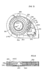
- Figure i is a top plan view of a preferred form of mixer, showing particularly fluid mechanical details entrance section which produce the smooth tangential introduction into the vortex mixer passage per se. patterns are shown by arrows and parasitic vortices 72 are surrounded by dotted lines for clarity.
- Figure 2 is a side cut-away view along sectional line showing details of the flow containing passages, particul- with respect to the vortex chamber per se.
- FIG 3 is a view along sectional A-A of Figure 1 showing the throttle.plate of Figure 1 in more detail.
- the rapezoidal throttle plate assembly shown can be replaced by the round-to-trapezoidal entrance section shown in Figs. 4 and
- FIG 4 shows a throttle body entrance section which could be bolted on along the surface of sectional A-A of Figure 1 as a direct substitution for the assembly shown in Fig. 3 where the entrance section body involves a transition from a circular butterfly air throttle to the trapezoidal shape of the entrance section along sectional A-A.
- Figures 4EE 4FF, 4GG, 4HH, 4JJ, and 4KK are half sectional views of the throttle body internal surface showing the transition between the round throttle plate area and the trapezoidal entrance area at surface A-A of Figure 1 for the entrance section structure of Figures 4 and 5. These views correspond to the planes identified by sectional lines EE, FF, GG, HH, JJ and KK respectively, shown in Fig. 4.
- Figure 5 is a side view of the round throttle plate to trapez:oidal entrance passage of Fig. 4, viewing on sectional 5-5 of Figure 4.
- Figures 5AA, 5BB, 5CC, and 5DD are sectional views of the throttle body internal surface, showing the transition between the round throttle plate area and the trapezoidal entrance area at surface A-A of Figure 1 for the entrance section structure of Figures 4 and 5, and corresponding to the planes identified by section lines AA, BB, CC, DD respectively, shown in Figure 5.
- Section lines AA to DD are shown in Figures 4EE, 4FF 4GG, 4HH : 4JJ, and 4KK.
- Figure 6 is a projection showing the tangential velocity in an irrotational flow vortex as a function of radius.
- Figure 7 shows the constant pitch spiral flow streamlines characteristic of an idealized irrotational flow vortex having neither turbulence nor molecular diffusion, with the streamline plotted which would be followed by an ink line tracer from the outside of the vortex to its central sink.
- Figure 8 shows an idealized irrotational flow vortex analogous to that of Figure 7, but with two streamlines plotted to illustrate the nesting of the streamlines.
- Figure 9 is also analogous to the flow pattern of Figure 7, and shows the nesting of 10 evenly distributed streamlines around the idealized vortex flow pattern.
- Figures 7, 8 and 9 are used to illustrate an important mathematical point about the mixing patterns within the vortex.
- Figures 10 and 11 illustrate the more complicated flow pattern which occurs if the boundary layer is not properly controlled. These figures are taken from Design Theory of Fluidic Components by J.M. Kirshner and Silas Katz, Academic Press, 1975.
- Figure 10 shows a cross section perpendicular to the axis of rotation of the vortex showing the more complicated vortex flow pattern which occurs because of boundary layer effects.
- Figure 11 is a diametral cross section through Figure 10 showing streamlines in the radial and axial direction which occur in this more complicated flow pattern.
- Figure 12 is analogous to Figure 2, showing the fluid mechanical effects of circumferential weirs, 41, shown in Figures 1 and 2, showing how these weirs form recirculating vortices at the boundary layer which permit the central flow of the vortex chamber to be a fair approximation of the irrotational flow vortex pattern illustrated in Figures 6, 7, 8, and 9.
- Figure 12a is an exploded view of the circled area of Figure 12, showing the flow between two weirs in more detail.
- Figure 13 is a top plan view of a vortex mixer analogous to that of Figure 1, wherein the entrance flow geometry is arranged for connection with a two venturi down draft carburetor (carburetor not shown).
- Figure 14 is a vertical sectional view of Figure 13 with the outside wall of the finned exhaust heat exchanger passage removed to show the geometrical arrangement of the fins.
- Figures 15, 16, 17 and 18 show a more primitive vortex mixer adapted to a downdraft carburetor.
- Figure 15 shows a diametral vertical sectional view of the mixer, with the section bisecting the venturi of the attached downdraft carburetor.
- Figure 16 is a top plan view along sectional 16-16 of Figure 15.
- Figure 17 is a side view along sectional 17-17 of Figure 15 showing the relationship between the carburetor throttle body and the flow deflectors.
- Figure 18 is a sectional view along broken sectional line 18-18 of Figure 17 further illustrating the shape of the deflectors.
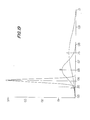
- Figures 19 and 20 illustrate why the homogeneous mixing of the current invention is practically useful, and helps explain the necessity for tight cylinder-to-cylinder,microscale volume, and time sample air-fuel ratio statistics of low NO x outputs are to be obtained with a fuel efficient lean burn engine.
- Figure 19 illustrates mixing statistics with the numerical example of Gaussian air-fuel ratio distributions A, B. and C.
- the graph makes clear the advantage of mixing in extending the lean limit of satisfactory combustion.
- Figure 20 plots experimental data which shows the vital importance of mixing and equivalence ratio on NO x outputs and engine thermal efficiency.
- FIGs 1, 2, and 3 A preferred form of the present invention is shown in Figures 1, 2, and 3 with an important practical modification shown in Figures 4, 4EE, 4FF, 4GG, 4HH, 4JJ, 4KK, and Figures 5, 5AA, 5BB, 5CC, and 5DD. Because the fluid mechanics involved is far from the training of conventional automotive engineers, these drawings will have to be treated several times in this specification from several points of view.
- FIG. 1 is a top plan view of the vortex mixer, with particular attention drawn by the flow lines to the fluid mechanics in the entrance passage.
- Figure 2 is a side sectional view along section line C-C of Figure 1 showing details not visible in Figure 1.
- Figure 3 is a view along sectional A-A of Figure 1 showing the rectangular shaped air throttle passage characteristic of Figure 1.
- the airflow to the engine is delivered to a passage 1 feeding throttle plate 4 which pivots on throttle plate shaft 2.
- the fuel introduction means in Figure 1 is shown by means of a fuel spray nozzle 6 spraying into the airflow at 8.
- the edges 10 of the rectangular shaped throttle plate 4 are cut away to produce a smooth, sharp edged orifice effect for the air- flow flowing between throttle plate 4 and throttle passage body 12.
- Throttle passage body 12 connects by fasteners to vortex mixer passage body 14.
- the details of the anics within the entrance section conduit 16 and within the main vortex flow chamber 18 will be discussed in considerably more detail later.
- the high speed flow past the upper edge of throttle plate 4 forms high speed wall-attached jet stream 20, which attaches to the wall of the mixer passage according to the Coanda effect, which will be discussed subsequently.
- the wall attached stream flows smoothly and is introduced into the generally radially symmetric vortex mixer chamber 18 in coherent and tangential form.
- the high velocity jet 22 formed downstream of the lower edge of throttle plate 4 also forms a Coanda wall-attached stream and is deflected by deflection means 24 so that it is deflected at 26 into the vortex chamber.
- the jet 22 flows past cusp 26 and interacts ballistically with static deflector 28 which deflects this jet into a smooth tangential introduction to the radially symmetric vortex chamber 18.
- These tangentially introduced flows from jets 22 and 20 flow via the Coanda effect in coherent form counterclockwise around the outside peripheral wall of chamber 18.
- the flow around the wall will pass by point 26 and merge with the flow from jet 22, interacting ballistically with deflector 28 and flowing again near the peripheral surface of the vortex chamber near surface line 30.
- the flow inside chamber 18 is therefore a swirling flow.
- This flow proceeds in a swirling manner inwardly toward the outlet 32 of the mixing chamber 18, which outlet 32 connects the vortex mixer with the intake manifold of the engine (not shown).
- the fluid mechanical relations within vortex chamber 18 form a flow pattern called an irrotational flow vortex. The details of this flow pattern will be discussed in more detail later.
- the swirling flow into outlet 32 is deflected by deflection vanes 34 so that the flow in the outlet section is not the strong irrotational flow vortex characteristic of the mixing channel 18 between the deflection vanes 34 and the outside wall of chamber 18 (going in the radial direction from the center 35 of the vortex mixing section 18).
- a strictly optional variable geometry deflection means 36, 38, 40 which can rotate (to a position denoted by the dotted lines 36a, 38a) to deflect the swirling flow within the vortex chamber 18 under conditions of wide-open throttle for engines where peak power is extremely important.
- This optional deflector eliminates an unavoidable flow resistance characteristic of the vortex flow pattern, and makes it possible for the vortex mixer of Figures 1, 2, and 3 to have excellent mixing under the lower loaded conditions characteristic of normal engine operation without any sacrifice of peak power flow capacity,
- the peripheral wall surface 42 of the vortex mixing channel 18 collects the liquid fuel introduced into the mixing channel due to centrifugal forces (analogous to those which operate in cyclone scrubbers).
- FIG. 3 is a view along sectional A-A of Figure 1 showing the roughly rectangular throttle plate 4 and showing the manner in which the throttle passage body 12 may be connected to the main vortex mixer body 14. A number of fluid mechanical details with respect to Figure 3 will be discussed later. However, it is worthwhile pointing out now that the generally rectangular throttle plate 4 has within it a notch 7 which forms the flow passage through which most of the idle airflow passes. Flow from this notch will form part of high-speed jet 20. The flow from the notch will be attached to both the side and top walls of the mixer.
- FIG. 3 A number of practical issues concerning the fastening And sealing of the throttle passage body 12 to vortex body 14 are illustrated in Figure 3.
- Bolt holes 13 for fastening are shown Also shown are pin holes 15 for alignment between throttle passage body 12 and vortex body 14.
- a groove 17 for an O-ring type deformable seal is also shown.
- O-ring type seals are useful for sealing pieces of the current invention, since the O-ring seal dces not protrude out between adjoining surfaces as conventional gaskets sometimes do. Because of details of the fluid mechanics in the mixer to be discussed later, careful alignment of the throttle passage body 12 with respect to vortex body 14, and smooth transitions between the airflow contacting surfaces are essential.
- Figure 4 and sectional view figures 4 EE, 4 FF, 4 GG, 4 HH, 4 JJ, and 4 KK combined with Figure 5 and sectional at sectional AA of Figure 1 exactly analogously to the entrance throttle passage body 12 of Figure 3, where the air throttle is a round butterfly valve and where the entrance section passage surfaces are faired to produce a fluid mechanically smooth transition between the round throttle plate and nearly rectangular opening at the entrance passage plane of sectional A A , with the surfaces and deflection arrangements shaped so that the predominant fraction of the high speed air flow past the throttle plate is delivered into the corners of the rectangular opening at sectional AA and along the near vertical surfaces 50 and 52, with the flow proceeding in a manner so as to minimize the fraction of the high speed flow which enters the vortex mixing section 14 adjacent surfaces 54 and 56.
- Figure 4 is a view from sectional A-A of Figure viewing the round- to-rectangular transition passage which replaces the rectangular throttle entrance section shown in Figure 3.
- Sectional view Figures 4 EE, 4 FF, 4 GG, 4 HH, 4 JJ, and 4 KK are included to illustrate the shape of this round- to-rectangular entrance passage 58.
- Figure 5 is a side view of the entrance passage of Figure 4 through sectional 5-5 which is a view from the other side of sectional GG.
- Figures 5 AA, 5 BB, 5 CC, and 5 DD show the internal surface shapes at sections AA, BB, CC, and DD respectively.
- the entrance passage assembly 58 consists of a complexly shaped cast body in which is mounted a generally round throttle plate 60 which pivots on throttle plate shaft 61.
- the round flow passage which accommodates throttle plate 60 is faired to a generally rectangular shape before it connects at the surface AA forming surface 64.
- Deflection vanes 62 serve to push the flow to the outside corners of the trapezoidal entrance section and minimize high speed flow adjacent surfaces 54 and 56.
- an idle flow passage 68 accommodating the majority cf the idle flow of air to the engine, and arranged so that this idle flow enters the vortex mixer in the form of a high speed jet hugging its corner to produce enhanced vortex velocity and mixing in a manner analogous to that discussed in Figure 3 with reference to throttle edge notch 7.
- This idle air flow is available to serve the purpose of an atomizing air flow if fuel is introduced upstream of the critical flow controlling restriction in this nozzle passage opening 68.
- Air flow and fuel flow past nozzle 68 is delivered in a form conducive.to a very efficient jet attachment to the corner wall, so that the high speed flow proceeds efficiently into the vortex chamber 18, and so that the fuel introduction into the vortex chamber is extremely rapid.
- the flow direction from nozzle 68 is specified with reference to the flow arrows shown in Figures 4 KK and 4 EE.
- the mixing and evaporating efficiency of the vortex mixer depend on the strength and flow pattern of the flow within vortex mixer chamber 18. What is desired is the strongest possible irrotational vortex flow rotating about the center 35. The stronger this flow, the more efficient the evaporation and the more efficient the mixing of the device.
- the strength of this vortex flow within mixing chamber 18 depends on the mass mean flow velocity of the flow entering the mixing chamber tangentially from jets 20 and 22. The greater the fraction of the isentropic expansion velocity past throttle plate 4 which can be delivered in coherent form tangentially past point 26 and point 30, the stronger the vortex will be and the better the mixer will function.
- the velocities, patterns, and turbulence levels are coupled.
- the detailed geometry between the opening of the throttle plate and these entrance points must be carefully controlled.
- the following chart shows the relationship between intake manifold pressure drop from atmospheric pressure and the isentropic expansion velocity to be expected directly downstream of the air throttling restriction in the vena contracta.
- the chart plots mass velocities and spatial velocities vs. the pressure drop across the throttle. Throttle pressure drop is expressed two ways, first as the ratio of manifold pressure to atmospheric pressure. For each pressure ratio the corresponding intake manifold vacuum in inches of mercury is set down.
- a jet entrains flow on both sides. If the jet is near a wall, fluid entrainment generates a reduced pressure on the wall side with respect-to the outside of the jet flow. Because of the pressure difference between the wall side and the outside of the jet, the jet flow path curves towards the wall (the jet is sucked towards the wall). As the jet bends towards the wall, the wall pressure becomes smaller, the suction stronger, and in consequence the jet attaches to the wall.
- This attachment effect is utilized in a number of important digital fluidic logic circuits, for example, those invented by Raymond Warren, et al, at Harry Diamond Laboratories.
- the Coanda, or wall attachment effect is of great importance to the design of the vortex mixer because a wall attached stream (particularly one adjacent to a properly set up parasitic vortex flow) spreads much more slowly than a non-wall-attached stream would. Since the jet velocity and the jet area are inversely related for a set mass flow rate, minimizing the jet spreading angle minimizes the jet flow area and maximizes the jet velocity, which is desired to strongly drive the vortex in chamber 18.
- Wall attached jet flows attach particularly well in corners of passages, such as occur at the outlet of throttle notch 7 in Figure 3, and at the corners of the flow passage shown in Figures 4 and 5. Flows attached to such corner passages have smaller losses than jets attached to extended flat surfaces.
- Notch 7 shown in Figure 3, and the deflectors 62 shown in Figure 5 are designed to put wall attached jets in passage corners for delivery to the vortex mixer passage 18.
- Idle flow nozzle 68 shown in Figure 4 serves the same purpose.
- the stability of a wall attached stream is not simply a function of the intrinsic instabilities which come from high local Reynolds numbers. Small variations in flow geometry which might at first appear to be insignificant can, by producing large disturbances in the jet, cause a magnification of turbulence which causes the jet to "break up.” Breakup drastically reduces the velocity and kinetic energy of the jet as it travels downstream from the disturbance, and therefore must be avoided if the vortex is to function efficiently.
- the setback (exemplified by setback distance Y) is important to the successful and reliable function of the vortex mixer shown in Figures 1 to 5. Streams which flow past a setback will, unless the setback is too great, reattach cleanly and with relatively small loss to a surface such as the downstream surfaces of channel 14.
- this protrusion is denoted as a "step-up"
- a high velocity element of fluid will collide with the step-up as with a brick wall.
- This flow element will deflect off the step-up in a manner which will strongly perturb the flow, break i n g up and destroying the coherence of the jet and so ruining the efficiency with which flow velocity is delivered to drive the vortex in the mixer chamber 18.
- the jet flow break- u p occurs, the kinetic energy of the jet is quickly lost because the jet spreads at such an angle that the momentum of the jet is dissipated in a large mass of turbulent fluid.
- step-up is permitted to occur adjacent the high-speed jets 20 and 22 (or the analogous jets which occur from the entance section shown in Figures 4, 4 EE, 4 FF, 4 GG, 4 H H , 4 JJ, 4 KK, 5, 5 AA, 5 BB, 5 CC, 5 DD)
- the fluidic efficiency and mixing efficiency of the vortex mixer will be significantly degraded from that which would occur without the step-up.
- the vortex mixer have particularly smooth surfaces. Surfaceswhich comefromeven a badly controlleddiecast process should be sufficient for the vortex minerfunction. Boundarylayer thicknesses are generally great enough to obsurethe effect of most commonly encountered surface roughnesses. However, large surface irregularities, such as grains of sand protruding in the wall-attached jet, grains sand can significantly degrade the fluidic efficiency (defined as the ratio of tangential introduction velocity to isentropic velocity past the throttle restriction) of the device. Generally, it is easy to maintain quality control well enough to avoid these obstructions.
- the fluidic function of the parasitic recirculating vortices 70 and 72 should be emphasized.
- the fluid mechanical relations are such that recirculating vortices 70 and 72 form in the entrance section.
- the geometry of deflector 28 assures that the relative positions of parasitic vortices 70 and 72 are relatively stable for a set air throttle angle (and that the parasitic vortices enlarge or shrink smoothly during throttle actuation). This is important: Downstream of a conventional carburetor throttle are parasitic vortices analogous to vortices 70 and 72.
- parasitic vortices 70 and 72 are highly desirable, in that these vortices form stable flow patterns which minimize the shear between the velocity of high speed jets 22 and 20 and the surrounding fluid. For this reason, the parasitic vortices 70 and 72 greatly decrease the spreading angle of these jets 20 and 22 and in consequence significantly improve the fluidic efficiency of the entrance passage geometry.
- hole 74 shows a desirable place to introduce exhaust gas recirculation flow if EGR is employed in the mixer. Any BGR flowpastnote by parasitic vortices 70 and 72 and smoothly introduced into the high speed jets flowing into the vortex mixing chamber 18.
- the purpose of the present invention is to produce a mixer producirs essentially perfect fuel-air homogeneity and rapid transient response. Looking at the flow patterns within the entrance section and then considering (as will be done later) the vortical flow pattern within mixing chamber 18, it should be apparent that the transient response of the mixing device depends largely on the detailed manner in which fuel is introduced into the mixing channel.
- the flow field in the generally annular volume between peripheral vortex wall 12and deflection vanes 34 will bein the form ofan irrota tional vortex flow field, where the angular momentum cf the fluid will be approximately conserved as it spirals inwardly to the vanes 34 for delivery to the outlet section 32, from whence the mixture flows to the intake manifold (not shown).
- This irrotational vortex flow field within vortex mixing chamber volume 18 is an extremely high velocity flow field, where the mean flow streamlines are dominated by the fluid mechanical relation of conservation of angular momentum, with turbulence superimposed on the mean flow streamlines.
- the swirling vortex flow within mixing chamber 18 is of such high velocity under normal engine operating conditions that liquid fuel delivered into the vortex is rapidly thrown to the out- side of the vortex and impacted against peripheral wall 42.
- the flow field is generally so strong, and the boundary layer , adjacent surface 42 so thin, that this liquid fuel generally atomizes and rotates with the flow field in the form of a "splash cloud" rotating very near the peripheral wall 42, impacting upon deflector 28 and then re-impacting and rotating again around the vortex outside wall 42 until it is fully evaporated.
- the effect is that fuel evaporates around the entire peripheral wall 42 of the vortex chamber.
- the boundary layer turbulence adjacent surface 42 in the vortex is such that thisevaporation process has the effect of introducing fuelvapor into relatively fuel-poor air in a structured turbulent flow mixing process characterized by extremely high mixing rates.
- this deflector When this deflector is in this extended position, it largely destroys the vortex flow pattern within mixing chamber 18, and in consequence reduces the flow resistence of the total mixing flow channel for wide open throttle power conditions. Under wide open throttle conditions very tight cylinder-to-cylinder distribution is of secondary importance so that destroying the vortex flow pattern is tolerable. Under the much more common part load conditions when the engine is throttled, the deflection means 36,38, and 40 do not in any way impair the mixing of the device.
- the mean flow streamline pattern described above is a good approximation of the real flowin a vortexmixer such as that shown as mixing chamber 1.8 if certain fluidic details are tended to. So long as turbulence levels are sufficiently low and boundary layer flows adjacent top 47 and bottom 43 are controlled, the physical relations of conservation of angular momentum make the mean flow streamlines in the real flow rather close to the pattern of an irrotational flow vortex. In the real flow pattern the mean pattern has relatively fine scale turbulent perturbations superimposed upon it. The resulting combination of large scale patterning with fine scale turbulence is useful for mixing.
- Figure 8 shows what would happen if the same flow situation as that of Figure 7 had an additional line of mixant introduced 180° around from the initial point of introduction.
- the vortex would have an outside circle 157 and a sink 158.
- a line of mixant would be introduced 159
- the numbers 159 are shown as the flow swirls in towards the sin: to identify that streamline.
- 180° from point 160 along circle 157 mixant is introduced atl62 and produces flow streamline 161.
- Flow streamline 161 is identified at several points to make it clear the manner in which the spiral159 and the spiral 161 nest
- Figure 8 illustrates what would happen in a mathematically perfect irrotational flow vortex with a sink, in the absence of either molecular diffusion or turbulent dif- fusion.
- Figure 9 is analogous to Figure 8, except now, rather than having two nested spiral streamlines, mixant would be introduced evenly around 10 points around the circumference of the vortex; and therefore, 10 different spiral lines would nest as shown.
- the mixing chamber 18 of the present invention will be evaporating mixture around the entire peripheiy 42 of the vortex. Because of the physics of the boundary layer turbulence on this outside wall, the flow structure will act to introduce the mixant (fuel) , not just around 10 points around the periphery, but around an effectively infinite number of points around the periphery. This means that if the liquid is well distributed around the circumference of the vortex peripheral wall (a point which will be discussed subsequently), the mean distance across which diffusion needs to occur in order to achieve essentially perfect homogeneity at the vortex sink is very short.
- the geometrical relations with respect to mixing illustrated by these figures are extremely important and do not become less important as the flow streamline structures become more complex; for any given flow structure, the flow structure will serve to stretch out the concentration gradients of species to be mixed and therefore, the flow structure will dramatically affect the rate at which mixing proceeds.
- the flow structure, or non-random streamline pattern can be thought of as a spatial transform of concentration fields as a function of time. There are flow transforms which are very conducive to mixing. The irrotational flow vortex is such a flow transform.
- mary other flow patterns which are not exactly irrotational flows can also have flow patterns very much conducive to mixing.
- the flow pattern in the vortex of the present invention will not be a perfect irrotational flow vortex.
- it will differ from a conventional irrotational flow vortex only in that the ratio of tangential to radial velocity will not quite be constant as a function of radius for the real flow.
- Boundary layer turbulence on the outside peripheral wall produces an effective multiple fuel point introduction characteristic for the evaporation process of the present invention.
- the combination of the fuel evaporation pattern, and the overall flow pattern produces mixing rates so fast that the mixture is effectively homogeneous at the mixer outlet.
- thermocouple at the peripheral wall of the vortex, the temperature of the liquid at the wall was measured. This temperature exactly determined the vapor pressure of the water at the outside wall. Then the wet bulb and dry bulb temperature of the air leaving the vortex chamber was measured. This determined the vapor pressure of water in the outlet air. It was found that: (1) for steady-stat conditions, there was no detectable difference in either the humidity or the temperature of the air exiting the vortex chamber outlet from radial position to radial position. (2) The vapor pres sure of water in the air at the vortex chamber outlet was always more than 60 percent of the vapor pressure of the water inside the vortex at the peripheral wall. Under many conditions, the vapor pressure at the outlet was more than 75 percent of the liquid water vapor pressure. A number of different flow conditions were run to collect this data. Consistently, the smallest fractions of the water vapor pressure occurred under flow conditions analogous to wide-open throttle type engine operation.
- the experiment strongly indicates that the wall temperature in a vortex mixer operating in an engine burning gasoline would need to be only a little hotter than the equilibrium air distillation temperature corresponding to the intake manifold pressure and mixture stoichiometry for a set engine condition, in order to completely evaporate , the fuel under steady-state, steady-flow conditions. If the peripheral wall of the vortex were operated at a temperature significantly higher than the equilibrium air distillation temperature corresponding to the mixture conditions, only a fraction of the peripheral wall would need to be wetted by the fuel in order to produce complete evaporation. This is practically important.
- the vapor pressure curves for most pure hydrocarbons are such that an 100°F increase in temperature increases vapor pressure by roughly a factor of 6 (5 to 7).
- peripheral wall was heated to a temperature 100°F above that of the equilibrium air distillation temperature of the mixture (which is often below 140°F). This would mean that if the entire peripheral wall of the vortex were wetted with gasoline, a roughly 6 times stoichiometric mixture would be produced by the vortex (for equilibrium reasons most of this fuel would recondense as smoke-sized particles, but this fact is of little interest to the present argument).
- the inventors have observed a vortex mixer operating on an engine. on conventional gasoline, by looking inside the vortex mixing chamber through a viewing window such as will be described with reference to Figure 12. Fuel was introduced just upstream of the main vortex flow field by means of an injection nozzle. The window made it possible to see the bottom and peripheral walls of the vortex mixer.
- the peripheral vortex wall analogous to wall 42 was more than 20°C above the equilibrium air distillation temperature characterise tic of the operating mixture, it was not possible with the naked eye to detect any trace of liquid phase in the vortex mixer, even though liquid phase was present in a splash cloud around the vortex peripheral wall. Neither the shinyness characteristic of wetting nor any blurring was visible to the eye, testifying to the physical reality of the splash cloud.
- Reynolds number modelling with air and water is useful for predicting evaporation lags, as was discussed above. (An advantage of water and air is that they are non-toxic and non-flanioable).
- Reynolds number modelling in a vortex mixer fabricated of transparent material with water as the working fluid and with ink injected at various points through syringe needles as tracer will give an appreciation for the details of the flowpattern which can be obtained inno other way. Askilled mechanics man, working with a Reynolds number water model of a specific vortex system will be able tc quickly see any fluid mechanical problems which occur and should be able to correct them.
- Reynolds number modelling with water is in- d ispensible because it permits direct visualization of the (inescapably somewhat complex) flow patterns.
- a Reynolds number model useful for water studies can be readily fabricated out of acrylic plastic or other transparent plastic. Simple pressure gauges and water flow gauges will permit Reynolds number analogies to be established.
- the water model technique can also be made to yield mixing statistics data by injecting salt water into the system at known points and then detecting the electrical resistance of the water somewhere downstream from the mixant introduction with a simple ionic probe (linked to a square wave generator to eliminate ionic corrosion drift). The ionic probe technique gives resolution of mixing statistics down to volumes of cubic millimeters or even smaller volumes.
- the efficiency of the vortex mixer is largely dependent on the fluidic efficiency of the vortex entrance section leading in to the vortex flow chamber per se.
- This fluidic efficiency is defined as the fraction of the isentropic velocity past the throttling restriction delivered tangentially and in coherent form to drive the vortex in the vortex mixing chamber (for example, mixing chamber 18 of Figs. 1 and 2).
- the high speed flow from the air controlling throttle is desired along the vortex walls roughly parallel to the vor- x tex outlet central axis 35, and not along the vortex walls perpendicular to the vortex outlet central axis.
- Figures 10 and 11 are taken from page 281 of this book and show the flow pattern which can be produced if the circumferential weirs 41, such as are shown in Figure 1 and Figure 2, are not used.
- Figure 10 is a view of the flow perpendicular to the axis of rotation of the vortex
- Figure 11 is a diametral section showing streamlines for the flow of FigurelO.
- What is called the developed region (or doughnut) is caused because of a boundary layer effect.
- the centrifugal forces in the flow in the vortex are important to determining the flow pattern. 2 Centrifugal force is proportional to re , and is therefore proportional to velocity squared. At the top and bottom surfaces of the vortex-containing channel, viscous forces slow down the flow in and near the boundary layer.
- FIG. 12 shows the flow pattern which is produced due to these weirs where Figure 12 is a diametral half section of a vortex channel such as that shown in Fi g . 14 and shows the velocities with respect to the radial direction (it should be clear that very significant tangential velocities, which are not shown in Figure 12, also exist in and out of the pattern).
- the effect of the circumferential weirs 81 is to stabilize small vortical flows between the weirs in such a manner that the effective boundary layer flow is well lubricated and where the great bulk of the flow energy in the vortex is in the form of a simple irrotational vortex flow.
- FIG 12 shows an enlarged sectional view of a vortex mixer such as that shown in Figures 13 and 14, with the addition of a transparent window 84 on the top of the vortex outlet.
- Window 84 makes possible the viewing of the vortex mixer flow channel below the point roughly corresponding to point 86, during actual operation of the vortex with a running engine.
- the window therefore, made possible viewing of the bottom of the vortex, including the weirs, as well as a considerable portion of the vortex peripheral wall.
- the window also made it possible to see the volume in space into which the injection nozzle was directly injecting fuel. Viewing the operating vortex through window 84 was extremely revealing.
- the vortex mixing chamber shown in Figures 1 and 2 in combination either with the entrance geometry shown in Figure 3 or with the entrance geometry shown in Figures 4 and 5, is the preferred form of the vortex mixer invention.
- the mixer shown in Figures 1 and 2 all of the throttling pressure drop across the air-flow controlling throttle is available to drive the flow patterns of the vertex mixer.
- the mixer of Figures 1 and 2 can be adapted to a side-draft type of carburetor.
- the arrangement shown in Figures 1 and 2 is not adaptable to the more conventional sort of down-draft carburetor.
- the vortex chamber per se 218 of Figures 13 and 14 corresponds in all details to the vortex chamber per se 18 in Figures 1 and 2.
- the vortex mixer chamber 218 discharges into outlet 232 which is connected to an intake manifold (not shown) as before.
- Vortex chamber peripheral wall 242, weirs 241, outlet 232 and outlet ' deflector vanes 234 each function in a manner analogous to the corresponding parts in Figures 1 and 2.
- the mixer of Figures 13 and 14 differs from that shown in Figures 1 and 2 with respect to the entrance section geometry, although significant fluid mechanical analogies between the two sorts of entrance geometries are readily apparent.
- the entrance section geometry is adapted to receive an intake of fuel-air mixture from a conventional down-draft two barrel carbuertor (not shown) at openings 250.
- the flow from the carburetor flows past openings 250 into entrance source chamber 201, which is heated and inside which a significant amount of fuel evaporation occurs.
- Mixture from chamber 201 flows past a curved throttle plate 204 pivotting on shaft 205 and linked to the throttle linkage of the carburetor (not shown).
- the linkage between throttle 204 and carburetor must be arranged so that the pressure drop across throttle plate 204 is enough to drive a strong vortex, but still a low enough pressure drop to be tolerable with respect to the metering characteristics of the carburetor.
- Throttle 204 is a curved roughly trapezoidal throttle plate with parallel top and bottom sealing surfaces.
- This passage contains a small volume of water, but is otherwise evacuated so that the only gas within the chamber is water vapor. Because of this, the liquid interface of water inside 254 is always at its boiling and at its condensation temperature. The equilibration of temperature within passage 254 is therefore very fast. If any surface of passage 254 is cooler than the water interface, water vapor will rapidly condense upon it, providing heat of vaporization heat transfer to this cooler surface. Similarly, if any part of the liquid contracting surface of the passage 254 is hotter than another surface on 254, water at this hot surface will boil, providing very rapid heat transfer from the hot (evaporating) to the cool (condensing) surface. The result of this is that heat transfer within the volume of passage 254 is extremely rapid. Therefore the temperature of the surfaces of the passage 254 is quite uniform. Heat pipe passages analogous to that of 254 are quite convenient in pro/iding uniform heating to extended surfaces, and are useful in the heat exchanger design for a vortex mixer.
- the mixer shown in Figures 13 and 14 has some disadvantages in comparison to that shown with reference in Figs. 1, 2, 3, 4, and 5.
- the mixer of Figs. 13 and 14 involve an additional air throttle 204 downstream of the air flow throttles already provided with the down-draft carburetor, -and the carburetor throttles and the auxiliary throttle 204 must be carefully linked if proper carburetor metering is to be maintained.
- the requirement that the entrance section be heated complicates heat exchanger arrangements.
- the vortex mixer described in Figures 13 and 14 works very well. Experimental results obtained on a mixer similar to that shown in Figures 13 and 14 will be discussed later.
- FIG. 15 is a diametrical cross section of the mixer, involving a section through the central passage of a one venturi down-draft type carburetor.
- Figure 16 is a top plan view of Figure 15 taken along sectional line 16-16 with the top of the device removed to show the disposition of the angular weirs and deflectors.
- Figure 17 is a sectional of the carburetor and its corresponding deflectors 342 and 343 along sectional linel7-17of Figure 15.
- Figure 18 is a view of deflectors 342 and 343 along sectional line 18-18 of Figure 17.
- FIGS. 15 and 16 show a number of additional features
- the heat exchanger passage 334 includes within it heat resistant insulated material 339 to assist the warm-up characteristics of the vortex mixer.
- electrical resistance air heating wires 310 are shown schematically upstream of the choke of the carburetor 326.
- a cold-starting mixture can be achieved by choking until a sufficiency of light end components are available in the vortex chamber to produce an ignitable mixture for cold start-up.
- the maximum air fuel ratio is proportional to the vapor pressure of the pure compound fuel as a function of temperature.
- Figure 19 is a mathematically derived numerical example used to make clear a basic statistical argument.
- Figure 19 plots three different gaussian distributions, curve A, curve B, and curve C, each of which has the same total area under the distribution curve, but with the curves having different standard deviations.
- the curves plotted are for gaussian distributions (reasonably mixed systems are nearly gaussian) where the sample size of the distribution is so large that the curve is continuous and smooth.
- the smooth distribution high population approximation
- Figure 19 attempts to show in a visually clear way that the lean limit of satisfactory engine combustion shifts leaner (approacning the lean limit for perfect mixing) as the mixture becomes more and more homogeneous.
- Figure 20 plots data taken by the inventors at the ENGINE RESEARCH LABORATORY of the University of Wisconsin Department of Mechanical Engineering under the close supervision of Professors P. S. Myers and O. A. Uyehara. This data also is presented as Figure 60 of a co-pending patent application by Robert Showalter. All data points in Figure 20 are for minimum best torque spark advance.
- the work plots nitrous oxide per indicated horsepower hour (as grams N0 2 per indicated horsepower hour) versus the equivalence ratio of mixture burned for three different mixing cases. In the first case, the propane fuel was introduced into the intake port of the test engine and flowed past a rather conventions intake port and intake valve arrangement into the engine . combustion chamber, where it was burned.
- Equivalence ratio is defined as the ratio of the stoichiometric air-fuel ratio to the actual air-fuel ratio.
- the test data of Figure 20 is for propane. However, the NO x formation with gasoline is very similar to what occur when burning propane. Plotting equivalence ratio versus air fuel ratic for casoline gives the following correspondences;
- Figure 20 graphs variation of NO x output versus equivalence ration with the NO x output expressed as grams N0 2 per indicated horsepower hour on a logarithmic scale, since the NO output varied by more than a factor of a thousand over the range of the equivalence ratio plotted.
- the ordinate of the graph is equivalence ratio, as defined above.
- NO x output is an extremely strong function of equivalence ratio, and that the relationship between equivalence ratio and NOx output is extremely steep in the very lean range.
- Figure 20 also shows that with excellent mixing the optimal fuel consumption air-fuel ratio shifts leaner and to a lower NO x output value. The data show that the better the mixing, the better the efficiency and the lower the NO x output corresponding to the optimal equivalence ratio.
- the vortex mixer used alone with proper fuel air ratio programming appears to have the potential of passing the 1.0 gram per mile NO x standard with lean combustion and in a trim involving significant fuel economy advantages in comparison to conventional pre-emission control engines and also advantages with respect to three-way catalyst equipped engines.
- the vortex makes these good results possible by producing extremely homogeneous fuel air mixing.
- Figure 19 gives a graphical explanation of how improved mixing within the combustion chamber of an engine can widen the equivalence ratio of dilution limits (EGR limits) which permit stable and efficient combustion.
- Figure 19 illustrates microscale mixture sample variations in a hypothetical engine where the gross air-fuel-residual ratio from cycle-to-cycle or cylinder-to-cylinder is fixed but where the mixing inside any given cylinder is imperfect.
- Curve A, B, and C of Figure 19 plot distributions for microscale mixing sample volumes, where the number of sample volumes in each distribution is very large so that the smooth gaussian distribution shown is produced. It should be emphasized that the curves of Figure 19 illustrate a numerical example of a statistical argument, and do not constitute the results of measurement.
- Curve A has a mean equivalence ratio of .75, but has a standard deviation of .1 equivalence ratio for its distribution. Under the assumption that the fraction of the population of curve A leaner than .55 equivalence ratio will represent the misfire frequency, 'this mixture A will misfire in the engine about 2.25% of the time; by usual standards distribution A can be said to be at its lean misfire limit at a ratio somewhat richer that .75 stoichiometric.
- the standard deviation of the mixture plotted on curve B is half the standard deviation of curve A, or .05 equivalence ratio.
- a 2.5% misfire rate for distribution quality B occurs at an overall equivalence ratio of .65 stoichiometric, and so an engine with mixing such as that shown for curve B will have a misfire limit richer than .65 equivalence ratio.
- Curve C is shown with a standard deviation of .01 equivalence ratio and with the overall equivalence ratio of the mixture at .585.
- the mixture of curve C is much leaner than that of curve A or curve B, but because of curve C's tight mixing leaner than .55 equivalence ratio will occur ifthe sparkgap less than 1/1Oth of 1% of the time.
- mixturedistribution C with its mean at .585 stoichiometric, 1 have a misfire rate 25 times less than the misfire rate distribution of curve A even though curve A has a mean equivalence ratio of .75 equivalence ratio, and distribution C will also have a misfire rate only 1/25th as great as that of distribution B with its mean ratio of .65 stoichiometric.
- Better mixing (tighter statistics) than that shown in curve C would permit the misfire limit to be approached even more closely with satisfactory engine smoothness. Tightening mixture distributions in the cylinder permits a much closer approach to the ultimate physical misfire limits than can be achieved with less complete mixing. Satisfactory operation with very lean mixtures requires extremely tight microscale statistics.
- a properly designed vortex mixer has essentially perfect cylinder-to-cylinder fuel-air ratio delivery, and can be designed to deliver microscale fuel air mixing statistics much tighter than those shown in curve C of Figure 19. These attributes give the vortex mixer the potential for very low emissions in the lean burn regime for a properly set up engine.
- the vortex mixer is an air-fuel mixing device with small transient lags for both the fuel and the air. It is not a fuel-air metering device. If, under steady-state conditions,air-fuel ratio delivered into the vortex varies as a function of time, the air-fuel ratio of the mixture from the outlet of the vortex will vary in nearly the same way as a function of time. For this reason, a smoothly continuous fuel-air metering into the vortex is desirable. This smooth-fuel input can be achieved in a number of ways.
- Figure 20 shows that very low NO outputs are possible with lean combustion.
- the range of air-fuel ratios where the NO x is low is relatively narrow, and is relatively close to the engine misfire levels.
- the fuel-air metering system required for low NO x operation in the lean regime requires relatively accurate fuel-air metering.
- the air-fuel ratio ranges involved constitute a "small target" for the fuel-air metering device.
- the percentage metering errors tolerable in the lean regime are considerably wider than those required for adequate function with a three-way catalyst system.
- the present invention mixer makes possible significant improvements in engine performance with respect to fuel economy, emissions, and drivability.
- the vortex mixer eliminates the necessity to handle two-phase flows in intake manifold passages, and therefore the vortex mixer permits more open intake passages than would otherwise be commercially acceptable. These more open intake passages increase engine power.
- the vortex mixer since it is a very efficient mixer and fuel evaporator, is well adapted for efficient evaporation and mixing of any engine fuel. Because of well-known problems of fuel supply economics, fuels different from conventional gasoline are of commercial interest. Most of this interest centers around alcohols and fuels derived from hydrogenation of coal, particularly the hydrogen poor high octane fuels called napthalenics.
- Exhaust flow (and hence heat addition) past the vortex heat exchanger fins is conveniently controlled by means of a temperature controlled ported vacuum switch.
- a temperature controlled ported vacuum switch will automatically control the vortex exhaust flow to maintain the desired range of vortex temperature. Since the evaporation temperatures required for evaporating the alcohol are relatively low, such a ported vacuum switch controlled exhaust flow control will automatically adapt itself to varying alcohol percentages and the fuel supply to a vehicle.
- vortex mixer is well adapted to die-casting from aluminum. To minimize production costs, it is desirable to minimize the amount of metal in the vortex mixer. This weight minimization is also highly desirable in terms of rapid warm-up; the lighter the vortex mixer structure is, the more rapidly it can be heated up to steady-state temperature after a cold start.
- the heat exchanger relations in the vortex mixer are such that the heat exchanger fins can readily be made of alminum, and maximum fin temperatures can readily be held below 175 degrees C. It is desirable that the fin areas be arranged se that the temperature around the outside peripheral wall of the vortex mixer is relatively uniform. With a splash-cloud of fuel droplets, this temperature condition is relatively easy to arrange, but a very smooth temperature distribution around the outlet will involve some degree of em- perical trimming of fin areas based on data generated by thermocouples locatad around the vortex peripheral wall.
- vortex mixer functions as follows:
- the vortex air-flow pattern serves as an inertial separator with centrifugal forces generally in excess of a thousand "G's". Fuel droplets are flung to the outside peripheral wall of the vortex mixing chamber by these centrifugal forces. The combination of the centrifugal force and the rapidly swirling flow forms an equilibrium splash cloud around the vortex chamber outside wall. This splash cloud continuously sprays and wets the outside wall surface, which is heated for extremely rapid evaporation. The evaporation all around the vortex chamber outside wall combines with the vortex flow pattern of the air to produce exceptionally rapid and complete fuel air mixing within the vortex mixing chamber. The mixing chamber functions nicely under all engine operating conditions.
- the vortex At cold start, the vortex rapidly evaporates the light ends of the fuel, while the heavy ends of the fuel accumulate around the vortex peripheral wall. Excellent cold start characteristics are therefore possible without ever delivering a rich (pollution causing and fuel wasting) mixture to the engine cylinders.
- the vortex warms up rapidly. Under normal driving conditions the warm vortex feeds a homogeneous mixture of vaporized fuel and air to the intake manifold of the engine. Under very low manifold vacuum wide open throttle conditions the vortex flow slows down. Fuel is still evaporated from the mixing chamber walls, but heat transfer rates at the vortex wall interfaces are low enough that the air surrounding the fuel evaporating boundary layers is cold. Much of the evaporated fuel therefore recondenses, so that the vortex functions as a smoke generator. In this smoke generating mode the vortex mixer can function with very low flow resistance and will feed a relatively cold and dense charge to the engine cylinders for peak power.
- Figures 1 and 2 show views of a fluidically efficient vortex mixer
- the fluid mechanics within the vortex chamber per se and the details of the flow streamlines to the left of section AA should be essentially invarient regardless of whether the vortex of Fig. 1 is fed with an entrance section such as that shown in Figure 3 and Figure 1, or whether the substitute round to trapezoidal transition section shown in Figures 4 and 5 is substituted.
- Either throttle body containing entrance section assembly will deliver high velocity flow to the main body of the vortex mixer in a form which will efficiently drive an irrotational vortex within the vortex mixer chamber.
- a large number of views of the round throttle plate to trapezoidal entrance assembly were necessary to clarify its shape.
- a corner notch opening assured that a significant fraction of the idle air flow formed a jet which attached to the adjacent walls of a corner of the passage.
- a nozzle 68 is arranged for the same purpose.
- the high speed jet so formed attaches to the corner between two adjacent walls and flows smoothly into the main vortex chamber. Corner wall attached jets spread relatively slowly. Putting a large fraction of the idle flow into such a corner wall attached jet reduces losses in the vortex entrance section and drives a stronger vortical flow within the vortex mixer than would otherwise be possible under idle and off-idle engine operating conditions.
- Figures 6, 7, 8 and 9 explain the flow structure of an irrotational flow vortex, and show how this flow pattern is useful for mixing.
- Figure 12 explains in light of Figures 10 and 11 the function of vortex mixing chamber weirs, which permit the irrotational flow pattern to flow and be stable within the vortex mixing chamber.
- Figures 13 and 14 show a vortex mixer having vortex mixing chamber fluid mechanics nearly identical to the fluid mechanics shown with respect to Figure 1, but where the entrance section is specifically adapted for a down-draft carburetor.
- Figures 15, 16, 17 and 18 show a more primitive vortex mixer.
- FIGS 19 and 20 are included to explain the value of the vortex mixer operated as the lean burn system, and a number of issues which must be tended to for satisfactory lean operation with minimum NO x emissions were discussed.
Landscapes
- Engineering & Computer Science (AREA)
- Chemical & Material Sciences (AREA)
- Combustion & Propulsion (AREA)
- Mechanical Engineering (AREA)
- General Engineering & Computer Science (AREA)
- Exhaust-Gas Circulating Devices (AREA)
Applications Claiming Priority (2)
| Application Number | Priority Date | Filing Date | Title |
|---|---|---|---|
| US94538878A | 1978-09-25 | 1978-09-25 | |
| US945388 | 1978-09-25 |
Publications (2)
| Publication Number | Publication Date |
|---|---|
| EP0011360A1 true EP0011360A1 (fr) | 1980-05-28 |
| EP0011360B1 EP0011360B1 (fr) | 1985-04-10 |
Family
ID=25483023
Family Applications (1)
| Application Number | Title | Priority Date | Filing Date |
|---|---|---|---|
| EP79301982A Expired EP0011360B1 (fr) | 1978-09-25 | 1979-09-24 | Dispositif servant au mélange du carburant et de l'air dans les moteurs à explosion |
Country Status (3)
| Country | Link |
|---|---|
| EP (1) | EP0011360B1 (fr) |
| DE (1) | DE2967428D1 (fr) |
| WO (1) | WO1980000731A1 (fr) |
Cited By (5)
| Publication number | Priority date | Publication date | Assignee | Title |
|---|---|---|---|---|
| EP0021706A1 (fr) * | 1979-06-11 | 1981-01-07 | Merle Robert Showalter | Moteur à pistons avec moyens pour limiter de façon variable l'écoulement dans l'admission |
| EP0051364A3 (fr) * | 1980-10-24 | 1982-11-03 | Frank Graeme Benson Walker | Mélange air-combustible employant une chambre de tourbillonnement |
| EP0051992A3 (fr) * | 1980-11-07 | 1982-12-01 | Ronald Frederick Bourne | Carburateur et procédé de carburation |
| EP0113695A3 (fr) * | 1983-01-10 | 1985-05-15 | Automotive Engine Associates | Réduction des NOx résultant de sources de combustion hétérogène par utilisation de mélanges ultra-homogènes d'air et de gaz d'échappement |
| US6994913B1 (en) | 1999-09-30 | 2006-02-07 | Sekisui Chemical Co., Ltd. | Thermoplastic elastomer, use thereof, and process for producing the same |
Families Citing this family (4)
| Publication number | Priority date | Publication date | Assignee | Title |
|---|---|---|---|---|
| US4609342A (en) * | 1983-01-10 | 1986-09-02 | Automotive Engine Associates | Abatement of NOx from heterogeneous combustion sources by ultrahomogeneous air-EGR mixing |
| RU2187685C2 (ru) * | 2000-07-11 | 2002-08-20 | ОАО "Научно-исследовательское предприятие гиперзвуковых систем" | Завихряющее устройство для двигателя внутреннего сгорания |
| CN111692016B (zh) * | 2019-03-13 | 2024-07-23 | 华益机电有限公司 | 一种燃油供给系统 |
| CN115896705B (zh) * | 2022-12-28 | 2024-11-05 | 北京金轮坤天特种机械有限公司 | 多联体涡轮导向叶片等离子物理气相沉积涂层的喷涂方法 |
Citations (5)
| Publication number | Priority date | Publication date | Assignee | Title |
|---|---|---|---|---|
| US1419702A (en) * | 1921-07-14 | 1922-06-13 | Tartrais Eugene Henri | Combustion chamber for internal-combustion engines |
| FR743640A (fr) * | 1933-04-03 | |||
| US3443552A (en) * | 1966-12-13 | 1969-05-13 | Ernest A Von Seggern | Internal combustion engine,fuel supply system and process |
| DE1526694A1 (de) * | 1965-01-12 | 1970-01-22 | Kopa Richard Dusan | Stroemungserzeuger fuer eine zusammengesetzte zyklonische Stroemung,insbesondere fuer Vergaser von Brennkraftmaschinen |
| FR2318319A1 (fr) * | 1975-07-18 | 1977-02-11 | Secretary Industry Brit | Nebuliseur de carburant auto-regulateur pour moteur a combustion interne a allumage par etincelles |
Family Cites Families (13)
| Publication number | Priority date | Publication date | Assignee | Title |
|---|---|---|---|---|
| US1610541A (en) * | 1922-10-07 | 1926-12-14 | Jr John M Williams | Intake manifold and fuel vaporizer |
| US1686609A (en) * | 1926-10-22 | 1928-10-09 | Eclipse Petrol Economiser Syst | Vaporizer |
| US1970169A (en) * | 1932-10-04 | 1934-08-14 | Ernest R Godward | Liquid fuel mixture vaporizer |
| US2232413A (en) * | 1939-03-30 | 1941-02-18 | Steskal Rudolph | Internal combustion engine |
| US2314131A (en) * | 1939-11-09 | 1943-03-16 | Csaby Laszlo De | Gas generator |
| US2411204A (en) * | 1943-11-08 | 1946-11-19 | Graziano Joseph | Fuel vaporizer |
| US3376027A (en) * | 1964-02-19 | 1968-04-02 | Univ California | Fuel atomizing carburetors |
| US3395899A (en) * | 1965-09-28 | 1968-08-06 | Univ California | Carburetor |
| US3285588A (en) * | 1965-09-29 | 1966-11-15 | Gen Motors Corp | Carburetor temperature control |
| US3273161A (en) * | 1966-03-03 | 1966-09-13 | Keller Ind Inc | Fuel economizer and exhaust gas purifier device |
| US3498279A (en) * | 1968-03-04 | 1970-03-03 | Harvey E Seeley Jr | Fuel vaporizer for internal combustion engines |
| DE2125204A1 (de) * | 1971-05-21 | 1972-11-30 | Reiche & Co | Verfahren und Vorrichtung zur Starthilfe von Verbrennungskraftmaschinen |
| DE2524772A1 (de) * | 1975-06-04 | 1976-12-09 | Theo Goepel | Ansaugleitungsausbildung von verbrennungskraftmaschinen |
-
1979
- 1979-09-24 DE DE7979301982T patent/DE2967428D1/de not_active Expired
- 1979-09-24 WO PCT/US1979/000766 patent/WO1980000731A1/fr not_active Ceased
- 1979-09-24 EP EP79301982A patent/EP0011360B1/fr not_active Expired
Patent Citations (5)
| Publication number | Priority date | Publication date | Assignee | Title |
|---|---|---|---|---|
| FR743640A (fr) * | 1933-04-03 | |||
| US1419702A (en) * | 1921-07-14 | 1922-06-13 | Tartrais Eugene Henri | Combustion chamber for internal-combustion engines |
| DE1526694A1 (de) * | 1965-01-12 | 1970-01-22 | Kopa Richard Dusan | Stroemungserzeuger fuer eine zusammengesetzte zyklonische Stroemung,insbesondere fuer Vergaser von Brennkraftmaschinen |
| US3443552A (en) * | 1966-12-13 | 1969-05-13 | Ernest A Von Seggern | Internal combustion engine,fuel supply system and process |
| FR2318319A1 (fr) * | 1975-07-18 | 1977-02-11 | Secretary Industry Brit | Nebuliseur de carburant auto-regulateur pour moteur a combustion interne a allumage par etincelles |
Cited By (5)
| Publication number | Priority date | Publication date | Assignee | Title |
|---|---|---|---|---|
| EP0021706A1 (fr) * | 1979-06-11 | 1981-01-07 | Merle Robert Showalter | Moteur à pistons avec moyens pour limiter de façon variable l'écoulement dans l'admission |
| EP0051364A3 (fr) * | 1980-10-24 | 1982-11-03 | Frank Graeme Benson Walker | Mélange air-combustible employant une chambre de tourbillonnement |
| EP0051992A3 (fr) * | 1980-11-07 | 1982-12-01 | Ronald Frederick Bourne | Carburateur et procédé de carburation |
| EP0113695A3 (fr) * | 1983-01-10 | 1985-05-15 | Automotive Engine Associates | Réduction des NOx résultant de sources de combustion hétérogène par utilisation de mélanges ultra-homogènes d'air et de gaz d'échappement |
| US6994913B1 (en) | 1999-09-30 | 2006-02-07 | Sekisui Chemical Co., Ltd. | Thermoplastic elastomer, use thereof, and process for producing the same |
Also Published As
| Publication number | Publication date |
|---|---|
| EP0011360B1 (fr) | 1985-04-10 |
| DE2967428D1 (en) | 1985-05-15 |
| WO1980000731A1 (fr) | 1980-04-17 |
Similar Documents
| Publication | Publication Date | Title |
|---|---|---|
| US4318386A (en) | Vortex fuel air mixer | |
| US5512216A (en) | Cyclone vortex process | |
| US5672187A (en) | Cyclone vortex system and process | |
| US3336017A (en) | Compound cyclonic flow inductor and improved carburetor embodying same | |
| US4270508A (en) | Combustion control system | |
| CA1144831A (fr) | Moteur a pistons a forte turbulence en compression et faible emission de polluants, avec taux de vorticite optimisable | |
| US4744340A (en) | Vortex generator intake valve and system of using the same | |
| EP0011360B1 (fr) | Dispositif servant au mélange du carburant et de l'air dans les moteurs à explosion | |
| US4577602A (en) | High swirl very low pollution piston engine employing optimizable vorticity metering | |
| US4015574A (en) | Apparatus for improving fuel-air mixture | |
| CA1149692A (fr) | Dispositif pour ameliorer le rendement du carburant dans un moteur a combustion interne | |
| US4256066A (en) | Carburettor | |
| US4112892A (en) | Combustion control system for adding fluid above the butterfly valve | |
| US4434772A (en) | Combustion mixture generator for internal combustion engines | |
| CA1129283A (fr) | Melangeur air/carburant par tourbillonnement | |
| US4426967A (en) | Engine charge air temperature classifier | |
| US4233945A (en) | Carburetion in an internal combustion engine | |
| US4526729A (en) | Vortex carburetor | |
| US5123398A (en) | Carburetion system | |
| US4087493A (en) | Apparatus for providing a uniform combustible air-fuel mixture | |
| US4153028A (en) | Atomizer | |
| CA1060735A (fr) | Dispositif pour melanger a l'air un melange liquide vaporise | |
| RU2070656C1 (ru) | Способ образования топливовоздушной смеси в двигателе внутреннего сгорания и устройство для его осуществления | |
| US3057335A (en) | Preinduction means and method for treating a fuel air mixture | |
| US3298334A (en) | Device for injecting an additive into the output of a carburetor |
Legal Events
| Date | Code | Title | Description |
|---|---|---|---|
| PUAI | Public reference made under article 153(3) epc to a published international application that has entered the european phase |
Free format text: ORIGINAL CODE: 0009012 |
|
| AK | Designated contracting states |
Designated state(s): DE FR GB IT SE |
|
| 17P | Request for examination filed |
Effective date: 19801114 |
|
| RAP1 | Party data changed (applicant data changed or rights of an application transferred) |
Owner name: SIEWERT, CHARLES LEE Owner name: KRIESEL, KENNETH WAYNE Owner name: AUTOMOTIVE ENGINE ASSOCIATES |
|
| RAP1 | Party data changed (applicant data changed or rights of an application transferred) |
Owner name: AUTOMOTIVE ENGINE ASSOCIATES |
|
| ITF | It: translation for a ep patent filed | ||
| GRAA | (expected) grant |
Free format text: ORIGINAL CODE: 0009210 |
|
| AK | Designated contracting states |
Designated state(s): DE FR GB IT SE |
|
| REF | Corresponds to: |
Ref document number: 2967428 Country of ref document: DE Date of ref document: 19850515 |
|
| ET | Fr: translation filed | ||
| PLBE | No opposition filed within time limit |
Free format text: ORIGINAL CODE: 0009261 |
|
| STAA | Information on the status of an ep patent application or granted ep patent |
Free format text: STATUS: NO OPPOSITION FILED WITHIN TIME LIMIT |
|
| 26N | No opposition filed | ||
| PG25 | Lapsed in a contracting state [announced via postgrant information from national office to epo] |
Ref country code: SE Effective date: 19870925 |
|
| PG25 | Lapsed in a contracting state [announced via postgrant information from national office to epo] |
Ref country code: FR Free format text: LAPSE BECAUSE OF NON-PAYMENT OF DUE FEES Effective date: 19880531 |
|
| PG25 | Lapsed in a contracting state [announced via postgrant information from national office to epo] |
Ref country code: DE Effective date: 19880601 |
|
| GBPC | Gb: european patent ceased through non-payment of renewal fee | ||
| REG | Reference to a national code |
Ref country code: FR Ref legal event code: ST |
|
| PG25 | Lapsed in a contracting state [announced via postgrant information from national office to epo] |
Ref country code: GB Free format text: LAPSE BECAUSE OF NON-PAYMENT OF DUE FEES Effective date: 19881118 |
|
| EUG | Se: european patent has lapsed |
Ref document number: 79301982.9 Effective date: 19880906 |