EP0011380A1 - Dispositif de coupe de duite dans un métier à tisser sans navette - Google Patents
Dispositif de coupe de duite dans un métier à tisser sans navette Download PDFInfo
- Publication number
- EP0011380A1 EP0011380A1 EP79302195A EP79302195A EP0011380A1 EP 0011380 A1 EP0011380 A1 EP 0011380A1 EP 79302195 A EP79302195 A EP 79302195A EP 79302195 A EP79302195 A EP 79302195A EP 0011380 A1 EP0011380 A1 EP 0011380A1
- Authority
- EP
- European Patent Office
- Prior art keywords
- weft
- guide members
- cutting member
- cutting
- escape
- Prior art date
- Legal status (The legal status is an assumption and is not a legal conclusion. Google has not performed a legal analysis and makes no representation as to the accuracy of the status listed.)
- Granted
Links
- 238000010009 beating Methods 0.000 claims abstract description 13
- 235000014676 Phragmites communis Nutrition 0.000 claims description 23
- 239000004744 fabric Substances 0.000 claims description 21
- 230000001360 synchronised effect Effects 0.000 claims 2
- 239000003365 glass fiber Substances 0.000 description 4
- 238000003780 insertion Methods 0.000 description 3
- 230000037431 insertion Effects 0.000 description 3
- 238000009941 weaving Methods 0.000 description 3
- 230000000694 effects Effects 0.000 description 2
- 125000006850 spacer group Chemical group 0.000 description 2
- 229910000831 Steel Inorganic materials 0.000 description 1
- PNEYBMLMFCGWSK-UHFFFAOYSA-N aluminium oxide Inorganic materials [O-2].[O-2].[O-2].[Al+3].[Al+3] PNEYBMLMFCGWSK-UHFFFAOYSA-N 0.000 description 1
- 230000006866 deterioration Effects 0.000 description 1
- 239000012530 fluid Substances 0.000 description 1
- 238000010438 heat treatment Methods 0.000 description 1
- 239000010687 lubricating oil Substances 0.000 description 1
- 229910052573 porcelain Inorganic materials 0.000 description 1
- 230000002028 premature Effects 0.000 description 1
- 230000002265 prevention Effects 0.000 description 1
- 239000010959 steel Substances 0.000 description 1
Images


Classifications
-
- D—TEXTILES; PAPER
- D03—WEAVING
- D03D—WOVEN FABRICS; METHODS OF WEAVING; LOOMS
- D03D49/00—Details or constructional features not specially adapted for looms of a particular type
- D03D49/70—Devices for cutting weft threads
Definitions
- the present invention relates to a weft-cutting device in a shuttleless loom.
- wefts after being inserted are cut away on both sides of the woven cloth. Specifically, the cutting on the insertion side is effected before the subsequent insertion, namely at a predetermined point in time after the beating, while the cutting of the margin on the opposite side is effected after two to three picking operations.
- the weft-cutting device in an air-jet-type loom consists of a scissors-like cutter comprising two blades which are connected to each other by means of a pin in a press contact relationship, and driven by a cam or the like to be opened or closed synchronously with the operation of the loom, to effect the cutting.
- looms are designed to have a high operational speed which is as high as 500 RPN. Accordingly, the above-mentioned scissors-like cutters have to be opened and closed 500 times per minute, i.e., seven hundred and twenty thousand times per day. This means that, after a certain operational time length, the connection between the blades may become loose. Also, due to insufficient supply of lubricating oil, the blades may seize. Furthermore, sharp cutting cannot be expected when the cutting edge of the blades become worn and dull. In cutting glass fibers, for example, the cutting performance deteriorates in a short time so that the blade has to be ground in every 40 to 50 hours in order to ensure sharp cutting.
- the cutting device is not provided with cutting blades, but with a thin cutting plate.
- Weft which is brought to a predetermined location during or after the beating is engaged by a pair of weft guide members.
- the cutting plate is moved between the pair of guide members across the weft held thereby, and cuts the weft at the edge portion thereof.
- the cutting device according to the present invention provides an excellent cutting performance and has remarkable durability. This is due to the fact that the present invention excludes provision of cutting blades which, at the time of cutting glass fibers, are subjected to premature wear resulting in the deterioration in the cutting performance, as well as provision of scissors-like cutters which are in' sliding engagement under a high surface pressure. Moreover, the guide members for the weft serve to sufficiently tension the weft during cutting, and the timing of the cutting can be facilitated.
- the weft is engaged by the pair of weft guide members at a location which is in the neighbourhood of the extension line of the cloth fell. If the weft guide members are respectively provided with a hook-shaped holding portion, in which the weft is engaged, the weft at first has to be brought to a position above the extension line of the cloth fell, and then back toward the reed into the recess formed by the hook. In this case, the weft is held in a slightly loose condition, and not under maximum tension. Adding'to this, for yarns having a low elongation ratio, the so-called two.stage gripper is used to grip the weft.
- the gripping force is reduced so as to draw out the weft from the supply side and to further reduce the tension applied to the weft.
- the weft is further loosened so that it may not be properly held in position with sufficient tension and may sometimes escape from the hook-shaped recess of the guide member due to mechanical vibration of the loom. With such an escape, the weft cannot be cut by the cutting means so that a subsequent picking operation on the insertion side will be impossible.
- the cutting device in order to positively hold the weft in a predetermined location of the guide members, is provided with an escape-preventing member extending in a juxtaposed relationship with the guide members.
- This escape-preventing member is arranged such that as the weft tends to escape from the guide members, the weft abuts the escape-preventing member which then prevents escape of the weft.
- the cutting device in order to sufficiently tension the weft before being cut, to thereby shorten the selvage as far as possible, the cutting device is provided with a tensioning member which engages the weft before the engagement of the cutting member and the weft.
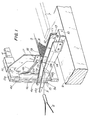
- FIG. 1 there is shown a first embodiment of the present invention, wherein reference numeral 1 denotes warps, 2 a nozzle for inserting wefts 3, 4-a reed, 5 a cloth fell, 6 a cloth, 7 a temple bar and 8 a frame having a top stay 9.
- a bracket 10 having a rectangular cross-section is fixedly mounted on the top stay 9 of the frame.
- this gap is sized to allow the movement of a plate 19 while contacting the opposing,side surfaces of the guide members 11, 12, or to be slightly greater than the thickness of the plate 19.
- the pair of the weft guide members 11, 12 are of identical configuration and respectively provided with inclined guide portions 11a, 12a extending between the free ends and the middle parts of the members.
- the guide portions 11a, 12a extend at an angle substantially identical to that of the lower warps forming a warp shed.
- the ends of the guide portions 11a, 12a terminating at the middle parts of the guide members are located at, or adjacent to the positions intersecting the extension line 5a of the cloth fell 5, and stepped to form recesses 11b, 12b which serve to engage the weft as shown in Figure 1.
- the pair of the weft guide members 11, 12 are disposed adjacent to the side frame 4a of the reed 4 whose blades 4b are not arranged at the location of the guide members 11, 12 so as to leave a space 4c permitting respective movement of the guide members 11, 12 at the time of beating.
- a weft guide member 14 which is identical in shape with the pair of guide members 11 and 12, and is provided accordingly with an inclined guide portion 14a and a recess 14b for engaging the weft.
- This g-ide member 14 is disposed slightly outside the reed 4.
- a guide rod 15 is provided, with one end 15a fixed to the upper frame 4d of the reed 4, extending parallel with, and slightly outside the guide member 14.
- a bracket 16 is fixed to the upper frame 4d of the reed 4, and an arm 17 is fixed to the bracket 16 extending downwardly in front of the reed 4.
- the arm 17 at its lower end co-operates with a clamp piece 18 to clamp a cutting plate 19 therebetween.
- the cutting plate may consist of a thin plate which is not formed with a blade.
- the cutting plate 19 is disposed between the pair of weft guide members 11, 12.
- the cutting plate 19 is moved between the pair of guide members 11, 12 forwardly and rearwardly (toward right and left in the figure) between the forward extreme position in which the cutting plate 19 is positioned in front of the recesses 11b, 12b and the rearward extreme position in which the cutting plate 19 is positioned behind the recesses 11b, 12b.
- the cutting plate 19 As the reed 4 is retracted and the cutting plate 19 moving between the pair of the guide members 11, 12 reaches the recesses 11b, 12b at a predetermined point in time, the cutting plate 19 at its edge facing the reed 4 engages the weft 3 held by the recesses 11b, 12b and cuts the same.
- the recesses 11b, 12b for holding the weft may be replaced by a stepped portion forming an upstanding portion extending toward the reed 4.
- the pair of weft guide members 11, 12 should be disposed in the vicinity of the cloth 6. Since a sufficient tensioning of the weft 3 may not be maintained by this measure alone, there is provided a further weft guide member 14 in juxtaposed relationship with the guide members 11, 12, and a guide rod 15 for guiding the weft 3 into the recess 14b of the guide member 14. If, however, the weft can be tensioned sufficiently without the guide member 14 and the guide rod 15, they may be dispensed with.
- Figure 2 shows a second embodiment of the present invention which differs from the arrangement shown in Figure 1 in the following points.
- a cutting plate 19 is fixedly connected to one end of a lever 21 which is provided on its middle portion with a shaft 21a rotatably journaled in a bearing 22.
- the lever 21 is biased by a spring 25 clockwise in the figure, which is arranged between a pin 23 secured to the lever 21 and a pin 24 secured to the frame 8, so that a cam follower 26 pivotally mounted on the other end of the lever 21 is urged against a cam 28 fixedly connected to the rotational shaft 27 of the loom.
- the cam 28 is formed with a lower portion 28a and a higher portion 28b which contacts the cam follower 26 at a predetermined point in time after completion of the beating.
- the lever 21 As the lower portion 28a of the cam 28 comes in abutting engagement with the cam follower 26, the lever 21 after clockwise rotation is brought to a position where the lower edge of the cutting plate 19 is positioned above the recesses 11b, 12b of the weft guide members 11, 12, while as the higher portion 28b of the cam 28 comes in abutting engagement with the cam follower 26, the lever 21 is rotated counter-clockwise so that the cutting plate 19 is inserted between the weft guide members 11, 12. Accordingly, the cutting plate 20 is arranged to vertically reciprocate between the guide members 11, 12.
- the cam 28 at its higher portion 28b abuts the cam follower 26 to cause a counter-clockwise rotation of the lever 21. Consequently, the cutting plate 19 is inserted between the pair of guide members 11, 12 and cuts at its lower edge the weft 3 held by the recesses 11b, 12b.
- FIGs 3, 4 and 5 show a third embodiment of the present invention.
- a gripper is shown at G.
- a plate-like member 30 for preventing escape of the weft.
- This escape-preventing member 30 is arranged between the bracket 10 and the weft guide members 11, 12; a spacer 31 being disposed to co-operate with the bracket 10 so as to clamp the escape-prevention member 30 therebetween, Suitable fastening means, such as bolts 32 and nuts 32', fixedly secure the guide members 11, 12, 14 and the escapement prevention member 30 to the bracket 10.
- the escape-preventing member 30 has at its free - end an upwardly inclined lower edge.
- the member 30 is formed with an edge 30b which steeply rises toward the extension line 5a of the cloth fell 5, and an edge 30a which is contiguous with the edge 30b and rises less steeply from the neighbourhood of the extension line 5a to the free end of the member 30.
- the edge 30a together with the inclined guide portion 12a (11a) defines a wedge-shaped guide space 33
- the edge 30b together with the recess 12b (11b) defines a holding space 34 which is closed when viewed from the side.
- the reed 4 is not provided with blades 4b so as to allow movement of the member 30 with respect to the reed 4.
- the weft As the weft is engaged in the recesses 11b, 12b, 14b of the guide members 11, 12, 14, the weft is also guided by the edge 30a of the escape-preventing member 30 and reaches the edge 30b where it is introduced into the holding space 34.
- the length of the weft path between the gripper G and the weaving edge tends to be elongated. But, as the gripping force of the gripper G is reduced, a full length of the weft is drawn out of its supply means so that the weft is not sufficiently tensioned even when held by the recesses 11b, 12b, 14b. Occasionally, due to mechanical vibration of the guide members 11, 12, 14, the weft may move upwardly and escape from the recesses.
- the escape-preventing member 30 may be disposed on the side of the guide member 11 facing the cloth 6.
- the escape-preventing member 30 may advantageously be disposed on the side of the guide member 12 which is remote from the cloth.
- FIGs 6, 7 and 8 show a fourth embodiment of the present invention.
- a tensioning rod 40 having a threaded end extending through the middle part of the arm 17.
- the tensioning rod 40 is fixed by a pair of nuts 41a, 41b which engage the threaded end of the rod 40 and clamp the arm 17 therebetween.
- the tensioning rod 40 extends downwardly, and is provided with a free end 40a which is so positioned between the weft guide member 12 and the escape-preventing member 30 that, as the reed 4 is retracted, the free end 40a moves across the extension line 5a of the cloth fell 5 before the cutting plate 19 reaches this line 5a.
- the weft 3 is held by the recesses 11b, 12b, 14b of the guide member 11, 12, 14, while escape of the weft from the recesses 11b, 12b, 14b is prevented by the member 30.
- the tensioning rod 40 moves between the weft guide 12 and the escape-preventing member 30 and reaches the holding space 34.
- the tensioning rod 40 engages the weft 3 to form a bend projecting toward the reed 4 so as to tension the weft.
- the cutting plate 19 engages at its lower edge with the weft held by, and tensioned between, the recesses 11b, 12b so as to effect cutting of the weft.
- the weft 3 is kept to extend straight between the recesses 11b, 12b just before being engaged and cut by the cutting plate 19, so that the length of the selvage can be reduced.
- the tensioning rod 40 is connected, similarly to the cutting plate 19, to the arm 17 and driven by the reed 4, no separate drive means therefor is required.
- the rod 40 may be provided separately, without connection to the arm 17, and driven synchronously with the above-mentioned timing sequence by means of a separate drive.
- the cutting plate may consist of quenched steel or alumina porcelain. In this case, durability of the cutting plate can be remarkably improved.
Landscapes
- Engineering & Computer Science (AREA)
- Textile Engineering (AREA)
- Looms (AREA)
Applications Claiming Priority (4)
| Application Number | Priority Date | Filing Date | Title |
|---|---|---|---|
| JP12465878A JPS5551848A (en) | 1978-10-12 | 1978-10-12 | Weft yarn cutter of shuttleless loom |
| JP124658/78 | 1978-10-12 | ||
| JP27626/79 | 1979-03-12 | ||
| JP2762679A JPS55122049A (en) | 1979-03-12 | 1979-03-12 | Weft yarn cutter of shuttleless loom |
Publications (2)
| Publication Number | Publication Date |
|---|---|
| EP0011380A1 true EP0011380A1 (fr) | 1980-05-28 |
| EP0011380B1 EP0011380B1 (fr) | 1983-03-16 |
Family
ID=26365582
Family Applications (1)
| Application Number | Title | Priority Date | Filing Date |
|---|---|---|---|
| EP79302195A Expired EP0011380B1 (fr) | 1978-10-12 | 1979-10-12 | Dispositif de coupe de duite dans un métier à tisser sans navette |
Country Status (4)
| Country | Link |
|---|---|
| US (1) | US4275773A (fr) |
| EP (1) | EP0011380B1 (fr) |
| CS (1) | CS221528B2 (fr) |
| DE (1) | DE2965041D1 (fr) |
Cited By (2)
| Publication number | Priority date | Publication date | Assignee | Title |
|---|---|---|---|---|
| EP0083748A1 (fr) * | 1981-12-11 | 1983-07-20 | Kabushiki Kaisha Toyoda Jidoshokki Seisakusho | Procédé et dispositif d'élimination d'un fil de trame défectueux dans un métier à buse |
| EP0131557A3 (en) * | 1983-06-23 | 1987-03-04 | Skandinaviska Jute Aktiebolaget | Weft cutting device on looms |
Families Citing this family (8)
| Publication number | Priority date | Publication date | Assignee | Title |
|---|---|---|---|---|
| JPS5933785U (ja) * | 1982-08-24 | 1984-03-02 | 敷島紡績株式会社 | 布耳端切れ防止カツタ−ガイド |
| US4498504A (en) * | 1982-09-23 | 1985-02-12 | Burlington Industries, Inc. | Filling fringe waste reduction |
| US4531555A (en) * | 1983-01-19 | 1985-07-30 | Toray Industries, Inc. | Yarn cutter for shuttleless loom |
| EP0143119B1 (fr) * | 1983-12-01 | 1987-09-09 | Maschinenfabrik Sulzer-Rüti Ag | Dispositif coupe-fil pour métier à tisser, plus particulièrement pour les métiers à tisser à foule linéaire multiple |
| US4607667A (en) * | 1984-09-04 | 1986-08-26 | Texfi Industries, Inc. | Apparatus for severing inserted filling yarns and method |
| US4976292A (en) * | 1988-06-27 | 1990-12-11 | Tagawa Kikai Co., Ltd. | Weft end tensioning and detecting devices for shuttleless loom |
| DE4000856A1 (de) * | 1990-01-13 | 1991-07-18 | Dornier Gmbh Lindauer | Schussseitig angeordnete fadenschneidevorrichtung einer luftwebmaschine |
| DE4131167A1 (de) * | 1991-09-19 | 1993-03-25 | Dornier Gmbh Lindauer | Luftwebmaschine mit einrichtung zur bildung einer gewebegasse |
Citations (5)
| Publication number | Priority date | Publication date | Assignee | Title |
|---|---|---|---|---|
| GB985703A (en) * | 1961-02-14 | 1965-03-10 | Alsacienne Constr Meca | Improvements in shuttleless looms |
| GB1231736A (fr) * | 1968-07-06 | 1971-05-12 | ||
| DE2643847A1 (de) * | 1975-10-03 | 1977-04-14 | Alsacienne Constr Meca | Steuer- und schneideinrichtung fuer den schussfaden eines schuetzenlosen webstuhles |
| DE2312709B2 (de) * | 1972-03-17 | 1978-01-12 | Vsesojuznyj nautschno-issledovatelskij Institut legkogo i tekstilnogo maschinostroemja, Moskau | Vorrichtung fuer webmaschinen mit ortsfest angeordneten vorratsspulen zum festhalten des endes eines in das webfach eingetragenen schussfadens |
| DE2738478A1 (de) * | 1976-09-13 | 1978-03-16 | Atsushi Kitamura | Querfadenschneidvorrichtung in einer webmaschine |
Family Cites Families (5)
| Publication number | Priority date | Publication date | Assignee | Title |
|---|---|---|---|---|
| ES258709A1 (es) * | 1960-05-31 | 1960-12-01 | Figuerola Esquius Jose | Perfeccionamientos en los telares sin lanzaderas |
| US3792723A (en) * | 1972-02-08 | 1974-02-19 | D Titov | Weft thread end catching and holding mechanism |
| AT317800B (de) * | 1972-09-15 | 1974-09-10 | Voest Ag | Vorrichtung zum Aufrechterhalten der Spannung des in das Fach eingetragenen Schußfadens |
| US4088159A (en) * | 1976-02-06 | 1978-05-09 | Komarov Jury Ivanovich | Loom device for holding weft thread ends |
| US4134434A (en) * | 1976-03-11 | 1979-01-16 | Vyzkumny A Vyvojovy Ustav Zavodu Vseobecneho Strojirenstvi | Weft cutting device in looms with mechanisms for multi weft weaving |
-
1979
- 1979-10-10 US US06/083,548 patent/US4275773A/en not_active Expired - Lifetime
- 1979-10-12 EP EP79302195A patent/EP0011380B1/fr not_active Expired
- 1979-10-12 CS CS796944A patent/CS221528B2/cs unknown
- 1979-10-12 DE DE7979302195T patent/DE2965041D1/de not_active Expired
Patent Citations (5)
| Publication number | Priority date | Publication date | Assignee | Title |
|---|---|---|---|---|
| GB985703A (en) * | 1961-02-14 | 1965-03-10 | Alsacienne Constr Meca | Improvements in shuttleless looms |
| GB1231736A (fr) * | 1968-07-06 | 1971-05-12 | ||
| DE2312709B2 (de) * | 1972-03-17 | 1978-01-12 | Vsesojuznyj nautschno-issledovatelskij Institut legkogo i tekstilnogo maschinostroemja, Moskau | Vorrichtung fuer webmaschinen mit ortsfest angeordneten vorratsspulen zum festhalten des endes eines in das webfach eingetragenen schussfadens |
| DE2643847A1 (de) * | 1975-10-03 | 1977-04-14 | Alsacienne Constr Meca | Steuer- und schneideinrichtung fuer den schussfaden eines schuetzenlosen webstuhles |
| DE2738478A1 (de) * | 1976-09-13 | 1978-03-16 | Atsushi Kitamura | Querfadenschneidvorrichtung in einer webmaschine |
Cited By (2)
| Publication number | Priority date | Publication date | Assignee | Title |
|---|---|---|---|---|
| EP0083748A1 (fr) * | 1981-12-11 | 1983-07-20 | Kabushiki Kaisha Toyoda Jidoshokki Seisakusho | Procédé et dispositif d'élimination d'un fil de trame défectueux dans un métier à buse |
| EP0131557A3 (en) * | 1983-06-23 | 1987-03-04 | Skandinaviska Jute Aktiebolaget | Weft cutting device on looms |
Also Published As
| Publication number | Publication date |
|---|---|
| DE2965041D1 (en) | 1983-04-21 |
| EP0011380B1 (fr) | 1983-03-16 |
| US4275773A (en) | 1981-06-30 |
| CS221528B2 (en) | 1983-04-29 |
Similar Documents
| Publication | Publication Date | Title |
|---|---|---|
| EP0011380B1 (fr) | Dispositif de coupe de duite dans un métier à tisser sans navette | |
| EP0275479B1 (fr) | Moyens pour guider le movement d'une paire de pince-trame dans la foule d'un métier à tisser | |
| US4185667A (en) | Positioning and holding mechanisms for filling yarns in a shuttleless loom | |
| US3590880A (en) | Apparatus and method for operating a loom | |
| US4736777A (en) | Rapier for a shuttleless loom | |
| US5819812A (en) | Giver gripper for a gripper loom | |
| US4155378A (en) | Method for driving shuttles of a wave-shed machine, and wave-shed loom for carrying out the method | |
| US3927699A (en) | Weft carrier control apparatus | |
| EP0715009B1 (fr) | Moyen pour guider le mouvement d'une paire de griffes lelong de la foule de métiers à tisser | |
| US3874421A (en) | Carrier for weft insertion | |
| KR830001310B1 (ko) | 무저직기의 위사 절단장치 | |
| US2125894A (en) | Needle weaving loom | |
| US3431951A (en) | Loom filling positioner | |
| US3434508A (en) | Apparatus for weaving stiff filamentary material | |
| US4646790A (en) | Cutting mechanism for a weaving machine | |
| KR830001311B1 (ko) | 무저직기의 위사 절단장치 | |
| US6192943B1 (en) | Carpet loom for weaving warp pile fabric | |
| EP1057911B1 (fr) | Ensemble de formation de boucles | |
| US3424206A (en) | Shuttle and guiding structure therefor | |
| EP0131557B1 (fr) | Dispositif pour couper le fil de trame dans les métiers à tisser | |
| US3298400A (en) | Filling carrier for shuttleless looms | |
| US3126921A (en) | Protector means for shuttles | |
| US3868977A (en) | Spring mounted removable scissors for looms | |
| US4034781A (en) | Pile fabric forming apparatus having cooperating pairs of pile wires | |
| US6926041B2 (en) | Carpet loom |
Legal Events
| Date | Code | Title | Description |
|---|---|---|---|
| PUAI | Public reference made under article 153(3) epc to a published international application that has entered the european phase |
Free format text: ORIGINAL CODE: 0009012 |
|
| AK | Designated contracting states |
Designated state(s): CH DE FR GB IT NL |
|
| 17P | Request for examination filed | ||
| ITF | It: translation for a ep patent filed | ||
| GRAA | (expected) grant |
Free format text: ORIGINAL CODE: 0009210 |
|
| AK | Designated contracting states |
Designated state(s): CH DE FR GB IT NL |
|
| REF | Corresponds to: |
Ref document number: 2965041 Country of ref document: DE Date of ref document: 19830421 |
|
| ET | Fr: translation filed | ||
| PGFP | Annual fee paid to national office [announced via postgrant information from national office to epo] |
Ref country code: GB Payment date: 19911001 Year of fee payment: 13 |
|
| PGFP | Annual fee paid to national office [announced via postgrant information from national office to epo] |
Ref country code: FR Payment date: 19911007 Year of fee payment: 13 |
|
| PGFP | Annual fee paid to national office [announced via postgrant information from national office to epo] |
Ref country code: CH Payment date: 19911025 Year of fee payment: 13 |
|
| ITTA | It: last paid annual fee | ||
| PGFP | Annual fee paid to national office [announced via postgrant information from national office to epo] |
Ref country code: NL Payment date: 19911031 Year of fee payment: 13 Ref country code: DE Payment date: 19911031 Year of fee payment: 13 |
|
| PG25 | Lapsed in a contracting state [announced via postgrant information from national office to epo] |
Ref country code: GB Effective date: 19921012 |
|
| PG25 | Lapsed in a contracting state [announced via postgrant information from national office to epo] |
Ref country code: CH Effective date: 19921031 |
|
| PG25 | Lapsed in a contracting state [announced via postgrant information from national office to epo] |
Ref country code: NL Effective date: 19930501 |
|
| GBPC | Gb: european patent ceased through non-payment of renewal fee |
Effective date: 19921012 |
|
| NLV4 | Nl: lapsed or anulled due to non-payment of the annual fee | ||
| PG25 | Lapsed in a contracting state [announced via postgrant information from national office to epo] |
Ref country code: FR Effective date: 19930630 |
|
| REG | Reference to a national code |
Ref country code: CH Ref legal event code: PL |
|
| PG25 | Lapsed in a contracting state [announced via postgrant information from national office to epo] |
Ref country code: DE Effective date: 19930701 |
|
| REG | Reference to a national code |
Ref country code: FR Ref legal event code: ST |
|
| PLBE | No opposition filed within time limit |
Free format text: ORIGINAL CODE: 0009261 |
|
| STAA | Information on the status of an ep patent application or granted ep patent |
Free format text: STATUS: NO OPPOSITION FILED WITHIN TIME LIMIT |