EP0011432A1 - Träger für Fernbedienungsapparat - Google Patents
Träger für Fernbedienungsapparat Download PDFInfo
- Publication number
- EP0011432A1 EP0011432A1 EP79302476A EP79302476A EP0011432A1 EP 0011432 A1 EP0011432 A1 EP 0011432A1 EP 79302476 A EP79302476 A EP 79302476A EP 79302476 A EP79302476 A EP 79302476A EP 0011432 A1 EP0011432 A1 EP 0011432A1
- Authority
- EP
- European Patent Office
- Prior art keywords
- locking
- locking means
- assembly
- cable
- track
- Prior art date
- Legal status (The legal status is an assumption and is not a legal conclusion. Google has not performed a legal analysis and makes no representation as to the accuracy of the status listed.)
- Withdrawn
Links
- 230000033001 locomotion Effects 0.000 claims description 17
- 230000003134 recirculating effect Effects 0.000 claims description 3
- 238000005096 rolling process Methods 0.000 claims description 3
- 230000007246 mechanism Effects 0.000 description 3
- 230000000712 assembly Effects 0.000 description 2
- 238000000429 assembly Methods 0.000 description 2
- 239000000969 carrier Substances 0.000 description 2
- 239000000463 material Substances 0.000 description 2
- NJPPVKZQTLUDBO-UHFFFAOYSA-N novaluron Chemical compound C1=C(Cl)C(OC(F)(F)C(OC(F)(F)F)F)=CC=C1NC(=O)NC(=O)C1=C(F)C=CC=C1F NJPPVKZQTLUDBO-UHFFFAOYSA-N 0.000 description 2
- 230000032258 transport Effects 0.000 description 2
- 229910000906 Bronze Inorganic materials 0.000 description 1
- 229910000760 Hardened steel Inorganic materials 0.000 description 1
- 229910000831 Steel Inorganic materials 0.000 description 1
- 239000004809 Teflon Substances 0.000 description 1
- 229920006362 Teflon® Polymers 0.000 description 1
- 239000010974 bronze Substances 0.000 description 1
- KUNSUQLRTQLHQQ-UHFFFAOYSA-N copper tin Chemical compound [Cu].[Sn] KUNSUQLRTQLHQQ-UHFFFAOYSA-N 0.000 description 1
- 230000000994 depressogenic effect Effects 0.000 description 1
- 230000000694 effects Effects 0.000 description 1
- 238000001125 extrusion Methods 0.000 description 1
- 230000002452 interceptive effect Effects 0.000 description 1
- 238000000034 method Methods 0.000 description 1
- 230000004048 modification Effects 0.000 description 1
- 238000012986 modification Methods 0.000 description 1
- 230000008520 organization Effects 0.000 description 1
- 239000004033 plastic Substances 0.000 description 1
- 239000010959 steel Substances 0.000 description 1
Images


Classifications
-
- B—PERFORMING OPERATIONS; TRANSPORTING
- B23—MACHINE TOOLS; METAL-WORKING NOT OTHERWISE PROVIDED FOR
- B23Q—DETAILS, COMPONENTS, OR ACCESSORIES FOR MACHINE TOOLS, e.g. ARRANGEMENTS FOR COPYING OR CONTROLLING; MACHINE TOOLS IN GENERAL CHARACTERISED BY THE CONSTRUCTION OF PARTICULAR DETAILS OR COMPONENTS; COMBINATIONS OR ASSOCIATIONS OF METAL-WORKING MACHINES, NOT DIRECTED TO A PARTICULAR RESULT
- B23Q1/00—Members which are comprised in the general build-up of a form of machine, particularly relatively large fixed members
- B23Q1/0009—Energy-transferring means or control lines for movable machine parts; Control panels or boxes; Control parts
-
- B—PERFORMING OPERATIONS; TRANSPORTING
- B23—MACHINE TOOLS; METAL-WORKING NOT OTHERWISE PROVIDED FOR
- B23Q—DETAILS, COMPONENTS, OR ACCESSORIES FOR MACHINE TOOLS, e.g. ARRANGEMENTS FOR COPYING OR CONTROLLING; MACHINE TOOLS IN GENERAL CHARACTERISED BY THE CONSTRUCTION OF PARTICULAR DETAILS OR COMPONENTS; COMBINATIONS OR ASSOCIATIONS OF METAL-WORKING MACHINES, NOT DIRECTED TO A PARTICULAR RESULT
- B23Q1/00—Members which are comprised in the general build-up of a form of machine, particularly relatively large fixed members
- B23Q1/25—Movable or adjustable work or tool supports
- B23Q1/26—Movable or adjustable work or tool supports characterised by constructional features relating to the co-operation of relatively movable members; Means for preventing relative movement of such members
- B23Q1/28—Means for securing sliding members in any desired position
- B23Q1/285—Means for securing sliding members in any desired position for securing two or more members simultaneously or selectively
-
- B—PERFORMING OPERATIONS; TRANSPORTING
- B23—MACHINE TOOLS; METAL-WORKING NOT OTHERWISE PROVIDED FOR
- B23Q—DETAILS, COMPONENTS, OR ACCESSORIES FOR MACHINE TOOLS, e.g. ARRANGEMENTS FOR COPYING OR CONTROLLING; MACHINE TOOLS IN GENERAL CHARACTERISED BY THE CONSTRUCTION OF PARTICULAR DETAILS OR COMPONENTS; COMBINATIONS OR ASSOCIATIONS OF METAL-WORKING MACHINES, NOT DIRECTED TO A PARTICULAR RESULT
- B23Q1/00—Members which are comprised in the general build-up of a form of machine, particularly relatively large fixed members
- B23Q1/25—Movable or adjustable work or tool supports
- B23Q1/44—Movable or adjustable work or tool supports using particular mechanisms
- B23Q1/48—Movable or adjustable work or tool supports using particular mechanisms with sliding pairs and rotating pairs
- B23Q1/4804—Movable or adjustable work or tool supports using particular mechanisms with sliding pairs and rotating pairs a single rotating pair followed perpendicularly by a single sliding pair
- B23Q1/4809—Movable or adjustable work or tool supports using particular mechanisms with sliding pairs and rotating pairs a single rotating pair followed perpendicularly by a single sliding pair followed perpendicularly by a single rotating pair
-
- G—PHYSICS
- G11—INFORMATION STORAGE
- G11B—INFORMATION STORAGE BASED ON RELATIVE MOVEMENT BETWEEN RECORD CARRIER AND TRANSDUCER
- G11B33/00—Constructional parts, details or accessories not provided for in the other groups of this subclass
- G11B33/02—Cabinets; Cases; Stands; Disposition of apparatus therein or thereon
Definitions
- the present invention relates to carrier assemblies and more particularly to apparatus for holding an electrical controller unit which includes a trailing electric cable, and for easily repositioning the controller unit to a desired position at a work station.
- auxiliary equipment or apparatus can be mounted on a carrier assembly of size and complexity that generally is a function of the size and weight of such apparatus.
- a work light can easily be positioned at the end of an arm assembly with suitable linkages and biases so that the lamp can conveniently be positioned by the operator.
- microphones and simple push botton controllers can also be mounted on simple balanced linkage assemblies without great problems.
- a separate, wheeled cart can be provided which is sufficiently rugged to transport the apparatus.
- Some work stations do not readily permit the use of carts and many ancillary apparatus are either too bulky or include substantial cables which make the use of an articulated arm mounted at a single location impractical.
- auxiliary apparatus which is designed to control the operation of electronic equipment and which is too small to require a cart and yet too large to be mounted on an articulated arm. Further, such controllers include trailing electrical cables which should be kept out of the way of the operator.
- One typical control apparatus that does not lend itself readily to either a cart or an articulated arm is a multi-track tape recorder controller, which is sold as an accessory to a master tape recorder.
- the controller permits, at a remote location, a complete duplication of all controls that are otherwise located on the tape recorder console.
- a typical remote controller may be as small as one foot square and yet would have attached to it a substantial cable assembly which must attach to the recorder unit.
- a work station at a recording studio is primarily a large console which includes the necessary controls for several input and output channels.
- a typical console could range from six to eight feet in width, with the operator being retired to shift positions at the console, depending upon which input channels are being utilized and must be controlled.
- Such a console may be considered a work station, necessitating some freedom of movement of the operator with respect to that station.
- a remote control unit is provided for the tape recorder, then it is important for the operator of the console to have the tape controls convenient to where he happens to be, relative to the console.
- Such a remote tape controller depends, for its utility, upon being accessible to the operator, no matter what his position at the console.
- a separate cart carrying the remote control unit is not particularly convenient and has the problem of the trailing cable which must be accounted for.
- an articulated arm is inadequate. While the problem addressed is directed to the needs of the console operator in a recording studio, it is clear that similar problems exist in other-work stations when using other auxiliary and ancillary remote control units of complex electrical equipment.
- a carrier assembly that operates on a track that can be mounted to the underside of the console in the recording studio.
- a truck assembly is mounted on the track and includes a normally actuated locking brake which holds the truck in any preselected position on the track.
- An arm extends from the truck and includes a mounting head that is capable of rotation.
- the controller is mounted to the rotatable portion of the mounting head and a tilting mechanism may permit a fixed adjustment of the controller relative to the axis of rotation.
- the mounting head also includes a normally actuated, locking brake assembly that holds the controller in a desired orientation once the position has been selected.
- a single control lever when pushed, simultaneously releases both locking brakes and permits the operator to relocate the entire assembly relative to the track and to reposition the controller and reorient it with respect to the rotational axis. Releasing the handle re-engages both locking brakes.
- a unique cable carrier assembly is mounted on an extension of the carrier arm and includes a pair of cable carriers which support and suspend the cable.
- the carriers are free to translate in the axial direction within limits on the arm and are also loosely mounted so that they may rotate around an extension of the arm.
- the carrier assembly holds the cable with sufficient slack to permit repositioning and reorienting the controller without requiring an excessive amount of trailing cable, while holding the cable close to the console work surface and away from the legs of the operators seated at the console.
- the truck assembly rides on a specially designed track that includes a forward, rail portion which is engaged by a recirculating ball bearing, low friction support member, while a guideway is provided at the rear of the track in which a roller bearing assembly, attached to the truck, bears on the guideway.
- a frictional brake is normally biased into engagement with the rail assembly so as to hold the truck against translational motion.
- the rail portion of the track functions both as a support member and a fulcrum about which the truck assembly can rotate.
- the roller member which rides in a channel is maintained in engagement with the channel by the rotational moment created by the weight of the controller at the end of the arm, rotating about the rail portion. If the controller has been removed, the guideway prevents reverse rotation of the truck about the rail portion.
- the rotational head utilizes a splined member with a corresponding splined collar that is axially translatable with respect thereto.
- the mounting head By displacing the splined post in the axial direction, the mounting head is free to rotate, while releasing the splined post returns it into engagement with the splined collar, thereby locking it against further rotation.
- Simple translational motions are therefore required to release and energize both brake systems. Therefore, the brake release function can be accomplished through a simple lever combination which can easily be operated with one hand.
- the work station is a professional mixing console 10, typical of those installed in recording studios.
- the console 10 is a substantially rectangular table with various knobs, switches, sliders and other controls, which must be manipulated by an operator during the course of a recording session involving many electrical inputs and outputs.
- a remote controller unit which is connected to the tape recorder by a multi-strand electrical cable be provided to enable the operator to coordinate his various activities with a minimum of lost motion.
- Consoles such as the mixing console 10 of Figure 1, can be of any length, depending, of course, upon the numbers of input and output functions that must be controlled.
- a typical unit, such as is shown in Figure 1, may be seven feet or more in length. It is therefore necessary for an operator to move back and forth across the console, depending upon which controls he is operating during a recording session.
- the controller should be positionable in virtually any location and in any orientation relative to the operator's position at the console 10.
- a remote unit 12 is mounted on a carrier assembly 14 according to the present invention.
- a rather substantial cable 16, leading from the remote control unit 12, is held by a cable support assembly 18 that is a portion of the carrier assembly 14, which keeps the cable from interfering with the feet of the operator.
- the carrier assembly 14 and the remote control unit 12 carried thereby are shown in a first location at the left side of the console and, in phantom at the centre and at the right side of the console 10.
- the carrier assembly 14 includes a control handle 20 which is manually operable to reposition and reorient the remote control unit 12 for the convenience of the operator at the work station.
- the carrier assembly 14 as shown in Figure 1, includes a track assembly 22, a truck assembly 24, an arm assembly 26, a mounting head 28, and a stand portion 30 for holding the remote control unit 12.
- the track portion 22 includes a rail portion 32, which is a separate, cylindrical rod of case hardened steel that is attached to a pedestal portion 33, positioned to be close to the edge of the console 10 upon which the assembly is mounted.
- a guideway portion 34 which is in the shape of a channel.
- a substantially flat, brake portion 36 which is adapted to frictionally engage the truck portion 24.
- a screw and nut fastener 38 is countersunk to fasten the track portion 22 to the underside of the console 10 and, as shown, the fasteners are generally positioned in a line through the brake portion 36 of the track.
- the track 22 including the pedestal 33 and the guideway portion 34 can be an integral extrusion to which is attached the steel rail portion 32.
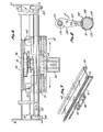
- the truck assembly 24 as seen in Figures 2, 6 and 7, includes a pair of recirculating ball bearing pillow block members 40 th-t are adapted to ride on the rail portion 32.
- a preferred pillow block is commercially available from Thomson Industries, Inc. of Manhasset, New York under the trademark "Super Ball Bushing" pillow blocks.
- the truck assembly 24 also includes a pair of roller elements 42 that are adapted to ride in the guideway portion 34 of the track 22.
- the truck 24 is free to move linearly, parallel to the front of the console 10. Through the use of such low friction, rolling elements, the truck 24 can easily be moved back and forth with little effort regardless of the position of the handle 20.
- a locking brake mechanism 44 is provided which includes a friction pad 46 that bears on the braking portion 36 of the track 22.
- the pad 46 is attached to a truck brake 48 which rides in a brake guide 50.
- a bias spring 52 fits over the brake guide 50 and is supported between the brake guide 50 and the brake 48 to normally bias the brake 48 into locking engagement with the brake portion 36 of the track 22.
- a substantially hollow arm 26 couples the truck assembly 24 to the mounting head 28.
- a brake lever 54 which includes a central fulcrum portion 56. Motion at one end of the lever 54 is converted into motion in the opposite direction at the other end.
- the one end of the brake lever 54 is coupled to the truck brake 48 and the other end is coupled to a brake yoke 58, which is connected to the mounting head 28.
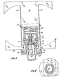
- the mounting head 28, as seen in Figures 2 and 3, is attached to the arm 26 with a body post 60.
- the body post includes a channel in which is placed a washer 62 of a bushing material such as bronze or teflon, as a sliding surface.
- a vertical portion of the body post 60 carries a second bushing 64 of a like material.
- a body member 66 then rests on the washer 62 and bushing 64 and is rotatable about the body post 60.
- the mounting head body 66 includes a handle yoke portion 68 which carries a handle pin 70 to connect the operating handle 20 with the mounting head body 66.
- An elongated slot (not shown) permits a pair of brake operating pins 74 to connect the handle 20 to a universal head 76.
- a brake post 78 is fastened to the universal head 76 with a plurality of fasteners 80.
- the brake post 78 is serrated with a plurality of equally spaced teeth and is adapted to mesh with a matching brake ring 82.
- the brake ring 82 is fixed to the body post 60 and is irrotational with respect thereto.
- the brake post is axially movable with respect to the brake ring 82.
- the brake post 78 In operation, when the handle 20 is depressed, the brake post 78 is elevated out of engagement with the brake ring 82, leaving the universal head 76 free to rotate relative to the body post 60.
- the universal head 76 permits the body 66 to rotate about the brake yoke 58 so that any rotational orientation may be selected.
- a relatively strong brake bias spring 84 urges the universal head 76 and the brake post 78 downward into engagement with the brake ring 82,thereby locking the mounting head 28 against further rotational motion.
- One or more locking screws 86 are installed in the body post 60 to hold the body member 66 in place against translational motion in the axial direction.
- the brake post 78 may be considered as a section of a splined shaft and the brake ring 82 is a splined collar. This arrangement permits a positive locking relationship within the mounting head and yet relative rotation in very small incremental amounts can be achieved.
- FIG 5 there is a perspective view of the mounting head 28 showing, in better detail, the attachment of the stand portion 30 and the control handle 20.
- Figures 2 and 3 are also useful in illustrating this relationship.
- the stand portion 30 includes a back plate 90 and a supporting lip 92 upon which the remote control unit 12 may rest.
- a plurality of resilient bumpers 94, together with clip fasteners 96 hold the control unit 12 in the stand 30, with spacing behind the control unit 12 for circulation of air.
- the back plate 90 has a pair of D-shaped segments 98 which are cut out and folded back to accommodate the hardware that mounts the stand 30 to the mounting head 28.
- An arcuate cutout 100 in the D-shaped wings 98 permits a tilting adjustment to be made of the stand 30.
- a locking knob 102 frictionally holds the stand 30 at the desired tilt angle.
- a cable carrier rod 110 extends from the arm 26 and is terminated with a locking nut 112.
- a pair of cable carrier swing arms 114 are loosely mounted on the rod 110 through an oversized aperture 116.
- a cable holder element 118 is pivotally mounted to the cable carrier swing arm 114 by a cable holder pin 120, about which the cable holder 118 may rotate.
- the cable holder 118 includes a pair of semi-cylinders 122, which may be as simple as a segment of plastic pipe of suitable diameter which has been cut in half.
- the semi-cylinders 112 are fastened to the cable holder 118 and the halves may be kept together either by an appropriate hinging mechanism 124 or through the use of simple cable ties 326, two of which are shown about the cable 16 in Figure 2.
- the cable ties 126 limit the axial travel of the cable 16 through the cable holder 118.
- the carrier assembly of the present invention transports a controller unit which has a trailing cable.
- a track assembly permitting lateral movement with respect to the work station as well as a rotating mounting head, an operator may press the operating control handle and, with one hand operation, can both translate and rotate the control unit to any convenient location and orientation at the work station.
- the controller unit itself is positioned on a stand that can be tilted for optimum access by the operator. The entire assembly is normally locked in place when the control handle is released.
- a novel cable support assembly carries the trailing cable above the floor and out of the way and permits the cable to easily follow the control unit without twisting or dragging.
- a frictional brake holds the truck against lateral movement with respect to the track, and a splined brake post co-operating with a splined brake ring locks the mounting head against undesired rotation.
Landscapes
- Engineering & Computer Science (AREA)
- Mechanical Engineering (AREA)
- Mechanical Control Devices (AREA)
Applications Claiming Priority (2)
| Application Number | Priority Date | Filing Date | Title |
|---|---|---|---|
| US957865 | 1978-11-06 | ||
| US05/957,865 US4221281A (en) | 1978-11-06 | 1978-11-06 | Carrier for remote controller |
Publications (1)
| Publication Number | Publication Date |
|---|---|
| EP0011432A1 true EP0011432A1 (de) | 1980-05-28 |
Family
ID=25500260
Family Applications (1)
| Application Number | Title | Priority Date | Filing Date |
|---|---|---|---|
| EP79302476A Withdrawn EP0011432A1 (de) | 1978-11-06 | 1979-11-06 | Träger für Fernbedienungsapparat |
Country Status (3)
| Country | Link |
|---|---|
| US (1) | US4221281A (de) |
| EP (1) | EP0011432A1 (de) |
| AU (1) | AU5214179A (de) |
Families Citing this family (2)
| Publication number | Priority date | Publication date | Assignee | Title |
|---|---|---|---|---|
| US6015274A (en) * | 1997-10-24 | 2000-01-18 | Hunter Fan Company | Low profile ceiling fan having a remote control receiver |
| DE102016005786A1 (de) * | 2016-05-13 | 2017-11-16 | Drägerwerk AG & Co. KGaA | Balkenversorgungseinheit zur Befestigung medizinischer Geräte an einer Decke |
Citations (1)
| Publication number | Priority date | Publication date | Assignee | Title |
|---|---|---|---|---|
| FR2092284A5 (de) * | 1970-04-07 | 1971-01-21 | Gutmann Kg Karl |
Family Cites Families (3)
| Publication number | Priority date | Publication date | Assignee | Title |
|---|---|---|---|---|
| US1151374A (en) * | 1914-09-26 | 1915-08-24 | Frederick M Moulton | Brake. |
| US2893518A (en) * | 1956-09-04 | 1959-07-07 | Alfred G Vanderbeck | Trolley anchoring device |
| US3548122A (en) * | 1966-12-14 | 1970-12-15 | Air Reduction | Mobile support for extensible helical members |
-
1978
- 1978-11-06 US US05/957,865 patent/US4221281A/en not_active Expired - Lifetime
-
1979
- 1979-10-24 AU AU52141/79A patent/AU5214179A/en not_active Abandoned
- 1979-11-06 EP EP79302476A patent/EP0011432A1/de not_active Withdrawn
Patent Citations (1)
| Publication number | Priority date | Publication date | Assignee | Title |
|---|---|---|---|---|
| FR2092284A5 (de) * | 1970-04-07 | 1971-01-21 | Gutmann Kg Karl |
Also Published As
| Publication number | Publication date |
|---|---|
| US4221281A (en) | 1980-09-09 |
| AU5214179A (en) | 1980-05-15 |
Similar Documents
| Publication | Publication Date | Title |
|---|---|---|
| US5246240A (en) | Apparatus for mounting equipment to wheelchairs | |
| US4863124A (en) | Corner work center | |
| US5636822A (en) | Computer mouse support | |
| US6634665B2 (en) | Quick release detachable wheels | |
| US5940912A (en) | Surgical armboard | |
| GB2530742A (en) | Deployment mechanism for a deployable table | |
| US7011321B2 (en) | Quick release detachable wheels | |
| US5193772A (en) | Artist's hand and brush guide for adjustable traveling mahl | |
| US4221281A (en) | Carrier for remote controller | |
| GB2102754A (en) | Tractor assembly for supporting and guiding a metal-working tool along a track fixed to a workpiece | |
| US4035096A (en) | Latching mechanism for a collapsible overhead guard | |
| JPH046976B2 (de) | ||
| US7147190B2 (en) | Multipositional accessory shelf for a computer mouse or other accessory items | |
| US3345751A (en) | Drafting table apparatus | |
| US4878409A (en) | Circular mat cutting apparatus | |
| US4776547A (en) | Platform support and shuttle | |
| JP2001071820A (ja) | 調節可能な非固定式クロス・バーを備える車両用物品キャリヤ装置 | |
| JP2007153320A (ja) | 片側開放型車両用物品キャリアシステム及び方法 | |
| US6808328B1 (en) | Shiftable keyboard tray and method of use | |
| US4725160A (en) | Mounting for a wheelchair service tray | |
| CN216102506U (zh) | 一种仪表板支架柔性辅助装配部装台 | |
| JPS635047Y2 (de) | ||
| CN118054610B (zh) | 一种紧凑型防爆电机固定装置 | |
| CN214238297U (zh) | 用于支重轮分拣的分拣机械手和分拣机器人 | |
| GB1572937A (en) | Profiling machine |
Legal Events
| Date | Code | Title | Description |
|---|---|---|---|
| PUAI | Public reference made under article 153(3) epc to a published international application that has entered the european phase |
Free format text: ORIGINAL CODE: 0009012 |
|
| AK | Designated contracting states |
Designated state(s): BE CH DE FR GB IT LU NL SE |
|
| STAA | Information on the status of an ep patent application or granted ep patent |
Free format text: STATUS: THE APPLICATION IS DEEMED TO BE WITHDRAWN |
|
| 18D | Application deemed to be withdrawn |
Effective date: 19810318 |