EP0011672B1 - Anordnung und Verfahren zur Bestimmung der Fehlerentwicklung in einer Schweissnaht - Google Patents
Anordnung und Verfahren zur Bestimmung der Fehlerentwicklung in einer Schweissnaht Download PDFInfo
- Publication number
- EP0011672B1 EP0011672B1 EP79102068A EP79102068A EP0011672B1 EP 0011672 B1 EP0011672 B1 EP 0011672B1 EP 79102068 A EP79102068 A EP 79102068A EP 79102068 A EP79102068 A EP 79102068A EP 0011672 B1 EP0011672 B1 EP 0011672B1
- Authority
- EP
- European Patent Office
- Prior art keywords
- passage
- gas
- weld deposit
- weld
- failure
- Prior art date
- Legal status (The legal status is an assumption and is not a legal conclusion. Google has not performed a legal analysis and makes no representation as to the accuracy of the status listed.)
- Expired
Links
Images


Classifications
-
- G—PHYSICS
- G01—MEASURING; TESTING
- G01M—TESTING STATIC OR DYNAMIC BALANCE OF MACHINES OR STRUCTURES; TESTING OF STRUCTURES OR APPARATUS, NOT OTHERWISE PROVIDED FOR
- G01M3/00—Investigating fluid-tightness of structures
- G01M3/02—Investigating fluid-tightness of structures by using fluid or vacuum
- G01M3/04—Investigating fluid-tightness of structures by using fluid or vacuum by detecting the presence of fluid at the leakage point
- G01M3/20—Investigating fluid-tightness of structures by using fluid or vacuum by detecting the presence of fluid at the leakage point using special tracer materials, e.g. dye, fluorescent material, radioactive material
- G01M3/22—Investigating fluid-tightness of structures by using fluid or vacuum by detecting the presence of fluid at the leakage point using special tracer materials, e.g. dye, fluorescent material, radioactive material for pipes, cables or tubes; for pipe joints or seals; for valves; for welds; for containers, e.g. radiators
- G01M3/225—Investigating fluid-tightness of structures by using fluid or vacuum by detecting the presence of fluid at the leakage point using special tracer materials, e.g. dye, fluorescent material, radioactive material for pipes, cables or tubes; for pipe joints or seals; for valves; for welds; for containers, e.g. radiators for welds
-
- G—PHYSICS
- G21—NUCLEAR PHYSICS; NUCLEAR ENGINEERING
- G21C—NUCLEAR REACTORS
- G21C17/00—Monitoring; Testing ; Maintaining
-
- Y—GENERAL TAGGING OF NEW TECHNOLOGICAL DEVELOPMENTS; GENERAL TAGGING OF CROSS-SECTIONAL TECHNOLOGIES SPANNING OVER SEVERAL SECTIONS OF THE IPC; TECHNICAL SUBJECTS COVERED BY FORMER USPC CROSS-REFERENCE ART COLLECTIONS [XRACs] AND DIGESTS
- Y02—TECHNOLOGIES OR APPLICATIONS FOR MITIGATION OR ADAPTATION AGAINST CLIMATE CHANGE
- Y02E—REDUCTION OF GREENHOUSE GAS [GHG] EMISSIONS, RELATED TO ENERGY GENERATION, TRANSMISSION OR DISTRIBUTION
- Y02E30/00—Energy generation of nuclear origin
- Y02E30/30—Nuclear fission reactors
Definitions
- This invention relates to an arrangement and method for detecting development of a failure within a weld deposit, particularly useful in nuclear reactor systems.
- An application where accurate and rapid indications of weld failure are particularly desirable is in nuclear reactors, particularly in relation to main structural components within the reactor vessel which support the nuclear core.
- the core of fuel assemblies is typically bottom supported by a lower support structure, control rods which are reciprocatingly insertable to control core reactivity are top mounted.
- In-service inspection programs have been instituted by the nuclear industry for inspection of such welds, including remote visual indicators useful, for example, in water-cooled reactors. With liquid metal cooled reactors, however, such visual indicators are not readily adaptable as a result of the opaque nature of the coolant.
- typical inspection systems require costly items such as multiple access ports and equipment and time consuming inspections carried out closely adjacent the welded area.
- liquid metal reactors which include the incorporation of tag gases within the fuel rods.
- the reactors include flow paths for directing tag gases released upon failure of a fuel rod to a monitoring and detection system which alerts the plant operator to such failure.
- Such reactors additionally are designed to prevent the accumulation of gas bubbles which could be swept through the core region.
- reactor internals are typically configured to vent any gas which enters the reactor system to a cover gas region above the core. The venting system thus permits gases released outside of the core to flow upwardly and eventually mix with any tag and fission product gases released from fuel assemblies within the core.
- German Utility Model DE-U-1903765 discloses an arrangement for testing weld structures of a container by means of a housing which may be placed over the weld structure to collect and monitor any gas leaking through the weld. With this arrangement however, which is considered for use as testing equipment after weld completion, no cracks which develop during operation can be found and they can certainly not be found before they extend fully through the weld structure.
- German Offenlegungsschrift DE-A1-2756646 discloses an arrangement and method for determining cracks in which a passage extends through a weld structure and the passage is evacuated and in communication with vacuum sensing means so that any crack through the passage will be detected as a result of loss of vacuum. Loss of such vacuum however, is not conclusive as vacuum may be lost by sensing equipment or communication line failure. Unnecessary failure signals however would, at least when they would occur in connection with a nuclear reactor, result in an expensive unnecessary reactor shut down.
- the present invention resides in an arrangement for detecting development of a failure in a weld deposit joining a first structure to a second structure by detecting a tag gas leaking through the weld deposit wherein a passage is formed in said structures, so as to extend through said weld deposit and wherein said passage extends from a surface of said first structure into said weld deposit characterized in that said passage is sealed by a plug with a preselected tag gas being contained under pressure in said passage; that means are provided for detecting said preselected tag gas; and that further means are provided for circulating a portion of the environment about said weld deposit such that upon development of a failure in said weld deposit a release of said preselected tag gas to said environment is carried to said detecting means.
- the passage or chamber is drilled from a surface of one component, through the weld deposit and into, but not entirely through, the second component.
- a preselected tag gas is placed within the passage or chamber, and the passage or chamber is sealed at its outer end by apply which may be threaded and/or welded. Any well-known means is provided to direct the environment immediately about the welded area, which can be liquid or gaseous, to other well-known apparatus which detects the presence of the tag gas.
- a trigger gas can also be incorporated with the tag gas to actuate a detection or analyzer system. Detection of the tag gas indicates that a failure has developed which provides a release path between the chamber and the surface of the weld deposit or the joined components.
- a plurality of chambers through a given weld area are each provided with different tag gases. Detection of several tag gases indicates that an alarm is caused by an extensive failure.
- a plurality of passage or chambers are incorporated in a single weld or in different welds, each with a different tag gas. Detection of a given tag gas thus evidences not only the existence of a weld failure, but also the location of the weld or the failed position within a specific weld.
- the invention also provides a method for detecting development of a failure in a weld deposit as set out in claim 6.
- the volume through which a chamber passes can be varied, extending, for example, over only one weld deposit boundary and terminating within, or at a surface of, the weld deposit.
- a chamber can also extend from a surface of one of the joined components, through the weld deposit and to the surface of another component, requiring two sealing plugs, among other configurations.
- the weld failure detection arrangement is particularly beneficial in the primary structural component welds of a liquid metal cooled nuclear reactor, such as the weld joining the reactor vessel to the core support structures. Leakage from a tag gas filled chamber is readily directed, by the upward flowing coolant and the configurations of the reactor and internals components, to the cover gas at the top of the reactor vessel.
- the cover gas can be continuously or intermittently monitored, or monitored by a detection system actuated by a trigger gas, for evidence of the tag gas as in proposed systems for monitoring fuel rod failures.
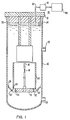
- a nuclear reactor vessel 10 including a sealed roof structure 12.
- a nuclerar core comprised of a plurality of fuel assemblies 14 each having a plurality of sealed fuel rods 16 containing nuclear fuel and a gas plenum.
- the fuel assemblies 14 are supported upon core support structures including a perforated lower core plate 18 joined to other components such as a transition 20, a cone 22 and a core barrel 2.4 by welds 26.
- a liquid coolant, such as sodium enters the vessel 10 through a plurality of inlet nozzles 28, flows upwardly about the fuel rods 14, absorbing heat energy, and is discharged from the vessel through outlet nozzles 30 to heat exchange apparatus, typically for the ultimate purpose of electric power generation. The coolant then returns to the inlet nozzles 28, completing a circuit through the substantially sealed reactor system.
- the level 32 of coolant within the vessel 10 is maintained so as to provide a cover gas space 34 within the reactor vessel.
- Cover gas samples are continuously or intermittently withdrawn from the gas space 34 by a monitoring system 36 through conduit 38 and directed to an analyzer 40 for determining the gas content. The samples can be returned to the reactor system or further treated.
- the fuel rods 16 can be provided with tag gases, typically non-radioactive isotopes, which, in the event of fuel rod failure, are released into the circulating coolant along with fission product gases and flow upwardly, ultimately entering the cover gas 34.
- the analyzer 40 upon monitoring of the cover gas, indicates the presence of a tag gas and accordingly a fuel rod failure.
- the analyzer 40 in presently proposed reactor systems can be activated by a trigger signal from activator 41 which reacts to the presence of a specified level of radioactive fission product gases released with the tag gases upon a fuel rod failure.
- Fig. 2 is representative of the welds, for example, the weld 26' between the transition 20 and cone 22.
- a passage or chamber 42 is drilled or otherwise made through selected portions of the component base metal 44, 46 and the weld deposit 48.
- chamber 42 extends from the surface 50 of the base metal 44, through a portion of the base metal 44, preferably the heat affected zone, through the weld deposit 48, and into the base metal 46.
- a preselected tag gas 52 is then injected into the chamber 42 and sealed therein by a plug 54.
- the plug is preferably both threaded into position and additionally welded or otherwise sealed about its periphery. Plural plugs in series can also be utilized for added integrity.
- the tag gas 52 is released to the surrounding environment 58.
- the surrounding environment is the reactor coolant through which the gas is directed to the cover gas 34 and the monitoring system 36.
- fuel rod failures emit not only the selected tag gas but also radioactive fission product gases which trigger the actuator 41, no similar releases of fission product gases arise from weld failure.
- a specific trigger gas such as long-lived radioactive krypton-85 can be incorporated in the tag gas to similarly activate the detection system 36. It will be evident that the trigger gas should be fast-acting in actuation of the detection system, since cover gas cleanup systems would otherwise remove the tag gases prior to their detection.
- the tag gas weld failure detection arrangement can equally be applied to welded structures in other nuclear and also non-nuclear applications, as exemplified in Fig. 3.
- a weld deposit 48 is disposed between two base metal components 44, 46.
- a portion of the environment about the welded area, illustrated by the dashed line 60, is directed by drive means such as a pump or fan 62 to an analyzer 40.
- Tag gas 52 released from the chamber 42 in the event of weld area failure is passed to the analyzer 40 and detected.
- a trigger gas can also be incorporated with the tag gas to actuate the analyzer 40.
- Fig. 3 also shows an alternative chamber 42 configuration, the chamber extending from a surface 50 of the base metal 44, through weld deposit 48 and base metal 46 to a surface 64.
- Two plugs 54 are accordingly utilized to seal the tag gas 52 within chamber 42.
- the chamber 42 can be of additional geometric configurations and can extend over additional selected areas.
- a plurality of tag gas filled chambers 42 can also be utilized in conjunction with a single weld deposit.
- the diameter of a hole of circular cross section or the size of any other configuration can be selected compatible with the size of the weld, the weld stress conditions and material sensitivity to stress concentration.
- the pressure of the tag gas placed within the chamber can also be selected in conjunction with the chamber volume to provide a sufficient quantity of tag gas for detection.
- the spacing of plural chambers along a weld should also be based upon the critical crack size for the specific application.
- a chamber will necessarily create a stress concentration which can reduce the fatigue life of a welded connection. This affect can be reduced by minimizing the size of a chamber and by adjusting the configuration of the chamber in any number of manners.
- a configuration such as shown in Fig. 4 can be utilized, the chamber volume being greater in a central region 66 and smaller at outer extensions 68.
- the enlarged central region 66 is machined into one or both of the base metal members and sealed by plug 70 prior to final machining of the base metal member preparatory to welding.
- the plug 70 preferably extends beyond the melting zone of the weld.
- the smaller diameter extensions 68 are drilled from an outer surface and into the region 66.
- the tag gas can either be sealed within region 66 prior to making of the extensions 68, or the extensions 68 can be utilized for tag gas charging.
- two or more chambers located in close proximity to each other within a given weld, each filled with a different tag gas can be utilized to enhance reliability of the system.
- Evidence of only one of these gases would tend to indicate a spurious signal, such as leakage passed a plug, as opposed to actual weld area failure.
- Simultaneous detection of the tag gases from separate chambers would tend to indicate an extensive failure.
- detection of a given tag gas further evidences not only the existence of a weld failure, but also the location of the failure within a specific weld.
- plural tag gas filled chambers can be, and in nuclear applications preferably are, positioned through a welded region at such intervals that the structural capability of the material between the structures would still be sufficient to ensure the structural integrity of the weld for its intended function when tag gas escapes from more than one chamber.
- This can be compatibly arranged particularly in liquid metal cooled reactors as major components are typically comprised of austenitic stainless steel which has a relatively long critical crack length.
- the critical crack length is here defined as the length at which the energy liberated as a result of an incremental crack growth is greater than the energy required to cause that incremental growth such that the crack extends in an unstable manner.
- Sealing of the tag gas within the chamber can be accomplished by a number of well known techniques such as sealing of the tag gas while the weld area is disposed in an environment of the desired gas at the desired pressure, or as shown in Fig. 5, by utilization of a container 72, having a rupturable end cap 74 which is pierced by a penetrator 76. Piercing can be accomplished upon insertion of the plug 54 or, for example, by electromagnetically moving the container 72 into contact with the penetrator 76, among other known techniques.
Landscapes
- Physics & Mathematics (AREA)
- Engineering & Computer Science (AREA)
- General Physics & Mathematics (AREA)
- Plasma & Fusion (AREA)
- General Engineering & Computer Science (AREA)
- High Energy & Nuclear Physics (AREA)
- Monitoring And Testing Of Nuclear Reactors (AREA)
- Investigating Or Analyzing Materials By The Use Of Ultrasonic Waves (AREA)
- Examining Or Testing Airtightness (AREA)
Claims (6)
Applications Claiming Priority (2)
| Application Number | Priority Date | Filing Date | Title |
|---|---|---|---|
| US05/965,364 US4259152A (en) | 1978-11-30 | 1978-11-30 | Weld failure detection |
| US965364 | 1978-11-30 |
Publications (2)
| Publication Number | Publication Date |
|---|---|
| EP0011672A1 EP0011672A1 (de) | 1980-06-11 |
| EP0011672B1 true EP0011672B1 (de) | 1984-03-21 |
Family
ID=25509872
Family Applications (1)
| Application Number | Title | Priority Date | Filing Date |
|---|---|---|---|
| EP79102068A Expired EP0011672B1 (de) | 1978-11-30 | 1979-06-22 | Anordnung und Verfahren zur Bestimmung der Fehlerentwicklung in einer Schweissnaht |
Country Status (6)
| Country | Link |
|---|---|
| US (1) | US4259152A (de) |
| EP (1) | EP0011672B1 (de) |
| JP (1) | JPS5575632A (de) |
| CA (1) | CA1131077A (de) |
| DE (1) | DE2966827D1 (de) |
| ES (1) | ES8100488A1 (de) |
Families Citing this family (7)
| Publication number | Priority date | Publication date | Assignee | Title |
|---|---|---|---|---|
| US4447388A (en) * | 1981-11-30 | 1984-05-08 | The United States Of America As Represented By The United States Department Of Energy | Bolt failure detection |
| US4675146A (en) * | 1983-10-21 | 1987-06-23 | The United States Of America As Represented By The United States Department Of Energy | Weld monitor and failure detector for nuclear reactor system |
| US4657729A (en) * | 1984-06-19 | 1987-04-14 | The United States Of America As Represented By The United States Department Of Energy | Solid tags for identifying failed reactor components |
| GB2231671B (en) * | 1989-05-10 | 1993-02-17 | Nnc Ltd | Movement detection system |
| CN101915644A (zh) * | 2010-07-27 | 2010-12-15 | 北京高能时代环境技术股份有限公司 | 一种利用正压检测土工膜焊缝安全的方法 |
| CN103884724B (zh) * | 2012-12-21 | 2016-03-30 | 国核电站运行服务技术有限公司 | 用于核反应堆压力容器接管焊缝检测的射线检测装置 |
| RU2596162C2 (ru) * | 2014-11-11 | 2016-08-27 | Открытое Акционерное Общество "Акмэ-Инжиниринг" | Способ и система управления вводом газа в теплоноситель и ядерная реакторная установка |
Family Cites Families (13)
| Publication number | Priority date | Publication date | Assignee | Title |
|---|---|---|---|---|
| NL254341A (de) * | 1959-07-31 | 1958-11-20 | ||
| NL255540A (de) * | 1959-09-04 | |||
| GB900348A (en) * | 1959-12-29 | 1962-07-04 | Atomic Energy Authority Uk | Improvements in or relating to fuel elements for nuclear reactors |
| GB897145A (en) * | 1960-01-19 | 1962-05-23 | Atomic Energy Authority Uk | Improvements in or relating to fuel elements for nuclear reactors |
| DE1903765U (de) * | 1963-02-23 | 1964-11-05 | Siemens Schukkertwerke Ag | Vorrichtung zur dichtigkeitspruefung von schweissnaehten. |
| US3489311A (en) * | 1967-05-25 | 1970-01-13 | Aerojet General Co | Tanks for storage of liquefied gas |
| GB1296396A (de) * | 1969-02-26 | 1972-11-15 | ||
| US3664922A (en) * | 1969-12-18 | 1972-05-23 | Combustion Eng | In-service inspection of reactor vessel welds |
| DE2133009A1 (de) * | 1971-07-02 | 1973-01-11 | Steinmueller Gmbh L & C | Behaelter fuer gasfoermige und/oder fluessige medien |
| FR2196070A5 (de) * | 1972-08-07 | 1974-03-08 | Nippon Kokan Kk | |
| US4033813A (en) * | 1975-10-22 | 1977-07-05 | The United States Of America As Represented By The United States Energy Research And Development Administration | Method of detecting leakage of reactor core components of liquid metal cooled fast reactors |
| UST963003I4 (en) | 1976-04-12 | 1977-10-04 | Westinghouse Electric Corportion | Method and apparatus for locating a defective tube of a liquid metal-to-water tube type heat exchanger |
| NL7712634A (nl) * | 1977-03-17 | 1978-09-19 | Continental Oil Co | Werkwijze en inrichting voor het vroegtijdig vaststellen van scheuren. |
-
1978
- 1978-11-30 US US05/965,364 patent/US4259152A/en not_active Expired - Lifetime
-
1979
- 1979-06-22 EP EP79102068A patent/EP0011672B1/de not_active Expired
- 1979-06-22 DE DE7979102068T patent/DE2966827D1/de not_active Expired
- 1979-06-29 CA CA330,928A patent/CA1131077A/en not_active Expired
- 1979-07-30 JP JP9619379A patent/JPS5575632A/ja active Pending
- 1979-07-30 ES ES482988A patent/ES8100488A1/es not_active Expired
Also Published As
| Publication number | Publication date |
|---|---|
| DE2966827D1 (en) | 1984-04-26 |
| ES482988A0 (es) | 1980-11-01 |
| ES8100488A1 (es) | 1980-11-01 |
| US4259152A (en) | 1981-03-31 |
| JPS5575632A (en) | 1980-06-07 |
| CA1131077A (en) | 1982-09-07 |
| EP0011672A1 (de) | 1980-06-11 |
Similar Documents
| Publication | Publication Date | Title |
|---|---|---|
| US4016749A (en) | Method and apparatus for inspection of nuclear fuel rods | |
| EP0011672B1 (de) | Anordnung und Verfahren zur Bestimmung der Fehlerentwicklung in einer Schweissnaht | |
| GB2202359A (en) | On-line monitoring and analysis of reactor vessel integrity | |
| US4039376A (en) | Method and apparatus for inspection of nuclear fuel rods | |
| US4650637A (en) | Method and apparatus for locating a leaking fuel rod in an assembly containing many rods | |
| US5210526A (en) | Automatic leak detection apparatus for process fluids from production and/or research plants, in particular energy plants | |
| KR102372548B1 (ko) | 방사능의 측정에 의해 핵분열 생성물을 검출하기 위한 분석 장치 | |
| US5539789A (en) | Method and apparatus for identifying failed nuclear fuel rods during refueling in a reactor core | |
| US3666625A (en) | Device for detection and location of failed nuclear fuel elements | |
| US5124114A (en) | Movement detection system | |
| US4517153A (en) | Device for removing cooling fluid, making it possible to locate defective arrays in a nuclear reactor in operation | |
| KR102681192B1 (ko) | 초음파 학습이미지 생성용 액체소듐환경 모사장치 및 그것을 이용한 초음파 학습이미지 생성방법 | |
| JP3889174B2 (ja) | 燃料破損検出用試料水採水方法と装置および燃料破損検出方法 | |
| JPH02126196A (ja) | 高圧圧力容器のリーク監視装置 | |
| JP2800930B2 (ja) | 原子炉用燃料要素のリーク検出方法及び原子炉用燃料要素 | |
| US4675146A (en) | Weld monitor and failure detector for nuclear reactor system | |
| JPS5810693A (ja) | 原子炉燃料破損位置検出系 | |
| RU2037818C1 (ru) | Способ обнаружения дефектных изделий | |
| Xiaohui | Analysis and Research on Diagnosis Methods of AFA 3G Fuel Assembly Leakage | |
| CN120800532A (zh) | 分段式液位计水淹试验方法及系统 | |
| JPH02126195A (ja) | 高温・高圧圧力容器のリーク監視装置 | |
| Wilson | An Engineering Test Program to Investigate a Loss of Coolant Accident | |
| JPH04204199A (ja) | 燃料破損検出装置 | |
| JPH0219737A (ja) | ライニング容器の補修法 | |
| Chokshi et al. | Review of nuclear power reactor coolant system leakage events and leak detection requirements |
Legal Events
| Date | Code | Title | Description |
|---|---|---|---|
| PUAI | Public reference made under article 153(3) epc to a published international application that has entered the european phase |
Free format text: ORIGINAL CODE: 0009012 |
|
| AK | Designated contracting states |
Designated state(s): BE DE FR GB IT NL |
|
| 17P | Request for examination filed |
Effective date: 19801209 |
|
| ITF | It: translation for a ep patent filed | ||
| GRAA | (expected) grant |
Free format text: ORIGINAL CODE: 0009210 |
|
| PGFP | Annual fee paid to national office [announced via postgrant information from national office to epo] |
Ref country code: DE Payment date: 19840313 Year of fee payment: 6 |
|
| AK | Designated contracting states |
Designated state(s): BE DE FR GB IT NL |
|
| PGFP | Annual fee paid to national office [announced via postgrant information from national office to epo] |
Ref country code: FR Payment date: 19840330 Year of fee payment: 6 |
|
| PGFP | Annual fee paid to national office [announced via postgrant information from national office to epo] |
Ref country code: BE Payment date: 19840331 Year of fee payment: 6 |
|
| REF | Corresponds to: |
Ref document number: 2966827 Country of ref document: DE Date of ref document: 19840426 |
|
| ET | Fr: translation filed | ||
| PGFP | Annual fee paid to national office [announced via postgrant information from national office to epo] |
Ref country code: NL Payment date: 19840630 Year of fee payment: 6 |
|
| PLBE | No opposition filed within time limit |
Free format text: ORIGINAL CODE: 0009261 |
|
| STAA | Information on the status of an ep patent application or granted ep patent |
Free format text: STATUS: NO OPPOSITION FILED WITHIN TIME LIMIT |
|
| 26N | No opposition filed | ||
| PG25 | Lapsed in a contracting state [announced via postgrant information from national office to epo] |
Ref country code: BE Effective date: 19850630 |
|
| BERE | Be: lapsed |
Owner name: WESTINGHOUSE ELECTRIC CORP. Effective date: 19850622 |
|
| PG25 | Lapsed in a contracting state [announced via postgrant information from national office to epo] |
Ref country code: NL Effective date: 19860101 |
|
| GBPC | Gb: european patent ceased through non-payment of renewal fee | ||
| PG25 | Lapsed in a contracting state [announced via postgrant information from national office to epo] |
Ref country code: FR Free format text: LAPSE BECAUSE OF NON-PAYMENT OF DUE FEES Effective date: 19860228 |
|
| PG25 | Lapsed in a contracting state [announced via postgrant information from national office to epo] |
Ref country code: DE Effective date: 19860301 |
|
| NLV4 | Nl: lapsed or anulled due to non-payment of the annual fee | ||
| REG | Reference to a national code |
Ref country code: FR Ref legal event code: ST |
|
| PG25 | Lapsed in a contracting state [announced via postgrant information from national office to epo] |
Ref country code: GB Effective date: 19881118 |