EP0012314A1 - Procédé et dispositif d'application d'une garniture dans une fermeture de récipient - Google Patents
Procédé et dispositif d'application d'une garniture dans une fermeture de récipient Download PDFInfo
- Publication number
- EP0012314A1 EP0012314A1 EP79104847A EP79104847A EP0012314A1 EP 0012314 A1 EP0012314 A1 EP 0012314A1 EP 79104847 A EP79104847 A EP 79104847A EP 79104847 A EP79104847 A EP 79104847A EP 0012314 A1 EP0012314 A1 EP 0012314A1
- Authority
- EP
- European Patent Office
- Prior art keywords
- closure
- liner stock
- liner
- annular
- extruder
- Prior art date
- Legal status (The legal status is an assumption and is not a legal conclusion. Google has not performed a legal analysis and makes no representation as to the accuracy of the status listed.)
- Granted
Links
Images



Classifications
-
- B—PERFORMING OPERATIONS; TRANSPORTING
- B29—WORKING OF PLASTICS; WORKING OF SUBSTANCES IN A PLASTIC STATE IN GENERAL
- B29C—SHAPING OR JOINING OF PLASTICS; SHAPING OF MATERIAL IN A PLASTIC STATE, NOT OTHERWISE PROVIDED FOR; AFTER-TREATMENT OF THE SHAPED PRODUCTS, e.g. REPAIRING
- B29C43/00—Compression moulding, i.e. applying external pressure to flow the moulding material; Apparatus therefor
- B29C43/02—Compression moulding, i.e. applying external pressure to flow the moulding material; Apparatus therefor of articles of definite length, i.e. discrete articles
- B29C43/18—Compression moulding, i.e. applying external pressure to flow the moulding material; Apparatus therefor of articles of definite length, i.e. discrete articles incorporating preformed parts or layers, e.g. compression moulding around inserts or for coating articles
-
- B—PERFORMING OPERATIONS; TRANSPORTING
- B29—WORKING OF PLASTICS; WORKING OF SUBSTANCES IN A PLASTIC STATE IN GENERAL
- B29C—SHAPING OR JOINING OF PLASTICS; SHAPING OF MATERIAL IN A PLASTIC STATE, NOT OTHERWISE PROVIDED FOR; AFTER-TREATMENT OF THE SHAPED PRODUCTS, e.g. REPAIRING
- B29C31/00—Handling, e.g. feeding of the material to be shaped, storage of plastics material before moulding; Automation, i.e. automated handling lines in plastics processing plants, e.g. using manipulators or robots
- B29C31/04—Feeding of the material to be moulded, e.g. into a mould cavity
- B29C31/041—Feeding of the material to be moulded, e.g. into a mould cavity using filling or dispensing heads placed in closed moulds or in contact with mould walls
-
- B—PERFORMING OPERATIONS; TRANSPORTING
- B29—WORKING OF PLASTICS; WORKING OF SUBSTANCES IN A PLASTIC STATE IN GENERAL
- B29C—SHAPING OR JOINING OF PLASTICS; SHAPING OF MATERIAL IN A PLASTIC STATE, NOT OTHERWISE PROVIDED FOR; AFTER-TREATMENT OF THE SHAPED PRODUCTS, e.g. REPAIRING
- B29C43/00—Compression moulding, i.e. applying external pressure to flow the moulding material; Apparatus therefor
- B29C43/02—Compression moulding, i.e. applying external pressure to flow the moulding material; Apparatus therefor of articles of definite length, i.e. discrete articles
- B29C43/04—Compression moulding, i.e. applying external pressure to flow the moulding material; Apparatus therefor of articles of definite length, i.e. discrete articles using movable moulds
- B29C43/06—Compression moulding, i.e. applying external pressure to flow the moulding material; Apparatus therefor of articles of definite length, i.e. discrete articles using movable moulds continuously movable in one direction, e.g. mounted on chains, belts
- B29C43/08—Compression moulding, i.e. applying external pressure to flow the moulding material; Apparatus therefor of articles of definite length, i.e. discrete articles using movable moulds continuously movable in one direction, e.g. mounted on chains, belts with circular movement, e.g. mounted on rolls, turntables
-
- B—PERFORMING OPERATIONS; TRANSPORTING
- B29—WORKING OF PLASTICS; WORKING OF SUBSTANCES IN A PLASTIC STATE IN GENERAL
- B29C—SHAPING OR JOINING OF PLASTICS; SHAPING OF MATERIAL IN A PLASTIC STATE, NOT OTHERWISE PROVIDED FOR; AFTER-TREATMENT OF THE SHAPED PRODUCTS, e.g. REPAIRING
- B29C70/00—Shaping composites, i.e. plastics material comprising reinforcements, fillers or preformed parts, e.g. inserts
- B29C70/68—Shaping composites, i.e. plastics material comprising reinforcements, fillers or preformed parts, e.g. inserts by incorporating or moulding on preformed parts, e.g. inserts or layers, e.g. foam blocks
- B29C70/78—Moulding material on one side only of the preformed part
- B29C70/80—Moulding sealing material into closure members
-
- B—PERFORMING OPERATIONS; TRANSPORTING
- B29—WORKING OF PLASTICS; WORKING OF SUBSTANCES IN A PLASTIC STATE IN GENERAL
- B29C—SHAPING OR JOINING OF PLASTICS; SHAPING OF MATERIAL IN A PLASTIC STATE, NOT OTHERWISE PROVIDED FOR; AFTER-TREATMENT OF THE SHAPED PRODUCTS, e.g. REPAIRING
- B29C43/00—Compression moulding, i.e. applying external pressure to flow the moulding material; Apparatus therefor
- B29C43/32—Component parts, details or accessories; Auxiliary operations
- B29C2043/3205—Particular pressure exerting means for making definite articles
- B29C2043/3255—Particular pressure exerting means for making definite articles springs
-
- B—PERFORMING OPERATIONS; TRANSPORTING
- B29—WORKING OF PLASTICS; WORKING OF SUBSTANCES IN A PLASTIC STATE IN GENERAL
- B29C—SHAPING OR JOINING OF PLASTICS; SHAPING OF MATERIAL IN A PLASTIC STATE, NOT OTHERWISE PROVIDED FOR; AFTER-TREATMENT OF THE SHAPED PRODUCTS, e.g. REPAIRING
- B29C43/00—Compression moulding, i.e. applying external pressure to flow the moulding material; Apparatus therefor
- B29C43/32—Component parts, details or accessories; Auxiliary operations
- B29C2043/3272—Component parts, details or accessories; Auxiliary operations driving means
- B29C2043/3283—Component parts, details or accessories; Auxiliary operations driving means for moving moulds or mould parts
-
- B—PERFORMING OPERATIONS; TRANSPORTING
- B29—WORKING OF PLASTICS; WORKING OF SUBSTANCES IN A PLASTIC STATE IN GENERAL
- B29C—SHAPING OR JOINING OF PLASTICS; SHAPING OF MATERIAL IN A PLASTIC STATE, NOT OTHERWISE PROVIDED FOR; AFTER-TREATMENT OF THE SHAPED PRODUCTS, e.g. REPAIRING
- B29C43/00—Compression moulding, i.e. applying external pressure to flow the moulding material; Apparatus therefor
- B29C43/32—Component parts, details or accessories; Auxiliary operations
- B29C43/36—Moulds for making articles of definite length, i.e. discrete articles
- B29C43/361—Moulds for making articles of definite length, i.e. discrete articles with pressing members independently movable of the parts for opening or closing the mould, e.g. movable pistons
- B29C2043/3615—Forming elements, e.g. mandrels or rams or stampers or pistons or plungers or punching devices
- B29C2043/3626—Forming elements, e.g. mandrels or rams or stampers or pistons or plungers or punching devices multi-part rams, plungers or mandrels
-
- B—PERFORMING OPERATIONS; TRANSPORTING
- B29—WORKING OF PLASTICS; WORKING OF SUBSTANCES IN A PLASTIC STATE IN GENERAL
- B29C—SHAPING OR JOINING OF PLASTICS; SHAPING OF MATERIAL IN A PLASTIC STATE, NOT OTHERWISE PROVIDED FOR; AFTER-TREATMENT OF THE SHAPED PRODUCTS, e.g. REPAIRING
- B29C43/00—Compression moulding, i.e. applying external pressure to flow the moulding material; Apparatus therefor
- B29C43/32—Component parts, details or accessories; Auxiliary operations
- B29C43/36—Moulds for making articles of definite length, i.e. discrete articles
- B29C2043/3676—Moulds for making articles of definite length, i.e. discrete articles moulds mounted on rotating supporting constuctions
- B29C2043/3689—Moulds for making articles of definite length, i.e. discrete articles moulds mounted on rotating supporting constuctions on a support table, e.g. flat disk-like tables having moulds on the periphery
-
- B—PERFORMING OPERATIONS; TRANSPORTING
- B29—WORKING OF PLASTICS; WORKING OF SUBSTANCES IN A PLASTIC STATE IN GENERAL
- B29C—SHAPING OR JOINING OF PLASTICS; SHAPING OF MATERIAL IN A PLASTIC STATE, NOT OTHERWISE PROVIDED FOR; AFTER-TREATMENT OF THE SHAPED PRODUCTS, e.g. REPAIRING
- B29C43/00—Compression moulding, i.e. applying external pressure to flow the moulding material; Apparatus therefor
- B29C43/32—Component parts, details or accessories; Auxiliary operations
- B29C43/36—Moulds for making articles of definite length, i.e. discrete articles
- B29C2043/3676—Moulds for making articles of definite length, i.e. discrete articles moulds mounted on rotating supporting constuctions
- B29C2043/3689—Moulds for making articles of definite length, i.e. discrete articles moulds mounted on rotating supporting constuctions on a support table, e.g. flat disk-like tables having moulds on the periphery
- B29C2043/3692—Moulds for making articles of definite length, i.e. discrete articles moulds mounted on rotating supporting constuctions on a support table, e.g. flat disk-like tables having moulds on the periphery cooperating with non rotating parts
-
- B—PERFORMING OPERATIONS; TRANSPORTING
- B29—WORKING OF PLASTICS; WORKING OF SUBSTANCES IN A PLASTIC STATE IN GENERAL
- B29C—SHAPING OR JOINING OF PLASTICS; SHAPING OF MATERIAL IN A PLASTIC STATE, NOT OTHERWISE PROVIDED FOR; AFTER-TREATMENT OF THE SHAPED PRODUCTS, e.g. REPAIRING
- B29C31/00—Handling, e.g. feeding of the material to be shaped, storage of plastics material before moulding; Automation, i.e. automated handling lines in plastics processing plants, e.g. using manipulators or robots
- B29C31/04—Feeding of the material to be moulded, e.g. into a mould cavity
-
- B—PERFORMING OPERATIONS; TRANSPORTING
- B29—WORKING OF PLASTICS; WORKING OF SUBSTANCES IN A PLASTIC STATE IN GENERAL
- B29C—SHAPING OR JOINING OF PLASTICS; SHAPING OF MATERIAL IN A PLASTIC STATE, NOT OTHERWISE PROVIDED FOR; AFTER-TREATMENT OF THE SHAPED PRODUCTS, e.g. REPAIRING
- B29C33/00—Moulds or cores; Details thereof or accessories therefor
- B29C33/0038—Moulds or cores; Details thereof or accessories therefor with sealing means or the like
-
- B—PERFORMING OPERATIONS; TRANSPORTING
- B29—WORKING OF PLASTICS; WORKING OF SUBSTANCES IN A PLASTIC STATE IN GENERAL
- B29C—SHAPING OR JOINING OF PLASTICS; SHAPING OF MATERIAL IN A PLASTIC STATE, NOT OTHERWISE PROVIDED FOR; AFTER-TREATMENT OF THE SHAPED PRODUCTS, e.g. REPAIRING
- B29C33/00—Moulds or cores; Details thereof or accessories therefor
- B29C33/02—Moulds or cores; Details thereof or accessories therefor with incorporated heating or cooling means
-
- B—PERFORMING OPERATIONS; TRANSPORTING
- B29—WORKING OF PLASTICS; WORKING OF SUBSTANCES IN A PLASTIC STATE IN GENERAL
- B29C—SHAPING OR JOINING OF PLASTICS; SHAPING OF MATERIAL IN A PLASTIC STATE, NOT OTHERWISE PROVIDED FOR; AFTER-TREATMENT OF THE SHAPED PRODUCTS, e.g. REPAIRING
- B29C33/00—Moulds or cores; Details thereof or accessories therefor
- B29C33/02—Moulds or cores; Details thereof or accessories therefor with incorporated heating or cooling means
- B29C33/04—Moulds or cores; Details thereof or accessories therefor with incorporated heating or cooling means using liquids, gas or steam
-
- B—PERFORMING OPERATIONS; TRANSPORTING
- B29—WORKING OF PLASTICS; WORKING OF SUBSTANCES IN A PLASTIC STATE IN GENERAL
- B29C—SHAPING OR JOINING OF PLASTICS; SHAPING OF MATERIAL IN A PLASTIC STATE, NOT OTHERWISE PROVIDED FOR; AFTER-TREATMENT OF THE SHAPED PRODUCTS, e.g. REPAIRING
- B29C33/00—Moulds or cores; Details thereof or accessories therefor
- B29C33/34—Moulds or cores; Details thereof or accessories therefor movable, e.g. to or from the moulding station
- B29C33/36—Moulds or cores; Details thereof or accessories therefor movable, e.g. to or from the moulding station continuously movable in one direction, e.g. in a closed circuit
-
- B—PERFORMING OPERATIONS; TRANSPORTING
- B29—WORKING OF PLASTICS; WORKING OF SUBSTANCES IN A PLASTIC STATE IN GENERAL
- B29L—INDEXING SCHEME ASSOCIATED WITH SUBCLASS B29C, RELATING TO PARTICULAR ARTICLES
- B29L2031/00—Other particular articles
- B29L2031/56—Stoppers or lids for bottles, jars, or the like, e.g. closures
- B29L2031/565—Stoppers or lids for bottles, jars, or the like, e.g. closures for containers
Definitions
- This invention relates to a method and an apparatus for forming a liner by feeding a liner stock into a container closure, especially a container closure having a relatively large diameter, and molding the liner stock into the desired shape.
- a conventional method for forming such a liner in a closure container comprises extruding a liner stock in the heated and molten state composed of a thermoplastic resin such as a polyolefin or a vinyl chloride resin into a nearly spherical or cylindrical form from an extruder, feeding it to the center of the central panel portion of the container closure, and then molding the liner stock into the desired shape while it is still in the hot and molten state (see, for example, Japanese Patent Publication No. 15447/61, Japanese Utility Model Publication No. 3515/72, and Japanese Laid-Open Patent Publications Nos. 110176/77 and 89583/78).
- a thermoplastic resin such as a polyolefin or a vinyl chloride resin
- the conventional method has important problems that have to be solved.
- that part of a container closure which essentially requires the presence of a liner is its peripheral edge portion corresponding to the opening end of a container.
- the shape of the essential part of the liner is annular.
- the liner stock extruded from the extruder is roughly spherical or cylindrical, and such a liner stock is fed to the center of the central panel portion of the closure. This makes it necessary the cause a greater part of the liner stock to flow to the peripheral edge of the container closure when molding the liner stock.
- a method was also suggested in the past which comprises molding a liner stock into an annular or wheel-like pre-formed liner, feeding the pre-formed liner into a container closure, heating the pre-formed liner until it is melted, and then molding it into the desired shape (see, for example, Japanese Laid-Open Patent Publications Nos. 45186/72 and 40355/74).
- This conventional method is complicated in the liner-forming process because it requires additional steps of pre-forming a liner stock into a preformed liner of a certain shape, and of heating the pre-formed liner fed into the container closure before it is molded.
- the pre-formed liner which has been formed into the desired shape by cooling is again heated before the molding step, and after the molding step, it is again cooled. This poses another problem that repeated heating and cooling degrade the properties of the resin which constitutes the liner.
- a method for forming a liner in a container closure which comprises extruding a liner stock in the heated and molten state into an annular shape by an extruder, positioning the annular liner stock at a predetermined location in a container closure, and molding the annular liner stock positioned in the closure into the desired shape while it is still in the hot and molten state.
- the liner stock in the heated and molten state is extruded into an annular shape and positioned in a predetermined site within the closure container.
- the liner stock can be molded into the desired shape without the need to cause a greater portion of it to flow greatly. Since there is no need to cause a greater part of the liner stock to flow greatly during the molding step, the liner stock can be molded without orienting it radially or otherwise. This, in turn, obviates the likelihood of crack formation in the liner which is due to the radial orientation of the liner stock.
- the molten liner stock is positioned at a certain locality in the container closure, the amount of the liner stock positioned at the center of the closure after the molding can be minimized or, if desired, reduced to zero. The amount required of the liner stock can therefore be minimized.
- the method of this invention involves extruding the liner stock in the heated and molten state, positioning it at a specified location within the container closure, and molding the liner stock into the desired shape while it is still hot and molten, the present invention does not require additional steps of molding the liner stock into a per-formed liner df the desired shape, and of heating the pre-formed liner fed into the container closure before it is molded. Another advantage is that since there is no need to cool and heat the liner stock repeatedly, the properties of the liner stock are not degraded.
- an apparatus for forming a liner in a container closure comprising a closure conveying means for conveying container closures to be lined through a predetermined passage; an extruder for extruding a liner stock in the heated and molten state in an annular shape into a closure conveyed to a liner stock feeding section by said conveying means and positioning the annular liner stock in a predetermined' location in the closure, said extruder including a heater member for melting the liner stock, at least one annular extrusion opening located opposite to the closure at said liner stock feeding section and a shutoff member for closing said extrusion opening; and a molding machine for molding the liner stock in the closure into the desired shape while it is still hot and molten, said closure having been conveyed to a liner stock molding section from the liner stock feeding section by said closure conveying means.
- an apparatus for forming a liner in a container closure comprising a closure conveying means for conveying closures to be lined through a predetermined passage; an extruder for extruding the liner stock in the heated and molten state into an annular shape including a heater section for melting the liner stock and an annular extrusion opening; a liner stock conveying means for cutting off at the extrusion opening the annular liner stock extruded from the extrusion opening of said extruder, conveying the cut liner stock to a closure conveyed to a liner stock feeding section by said closure conveying means, and positioning it at a predetermined location in the closure; and a molding machine for molding the liner stock in the closure into the desired shape while it is still hot and molten, said closure having been conveyed to a liner stock molding section from the liner stock feeding section by said closure conveying means.
- the apparatus of this invention illustrated includeds container closure conveying means 6 for conveying container closures 4 to be lined, a heating section 8 for heating the container closures 4, an extruder 10, and a molding machine 12 as principal constituent elements mounted on a base stand 20
- the heating section 8 heats the closures 4 to a temperature suitable for the adhesion of the molten liner stock to a predetermined position of the closures 4, for example about 200°C.
- the extruder 10 functions to heat a liner stock composed of a suitable thermoplastic resin such as polyolefins or vinyl chloride resins, extrude the resulting molten liner stock into an annular shape, and position the extrudate at a predetermined locality in the closure 4 heated to the suitable temperature by the heating section 8.
- the molding machine 12 acts on the molten liner positioned in the closure 4 and molds it into the desired shape.
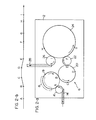
- the turret 18 rotates in the direction shown by an arrow in Figure 2-a, and conveys the closure 4 from the position A to a position shown by symbol B in Figure 2-a along an arcuate path through the heating section 80
- the heating section 8 includes a heater (not shown) of a known type such as a high frequency induction heater so that the closure 4 passing through the . heating section is heated, for example, to about 200°C.
- the closure 4 which has been conveyed to the position B by the turret 18 in the heating section is then transferred to a turret 20 in the liner stock feeding section which is rotating in the direction shown by an arrow in Figure 2-a, and is conveyed from the position B to a position shown by symbol E through positions shown by symbols C and D in Figure 2-a along an arcuate path.
- the extruder 10 is disposed above the turret 200 As is understood from Figure 2-b, the closure 4 conveyed by the turret 20 is gradually lifted in a perpendicular direction in a region ranging from the position B to the position C, and in the liner stock feeding section between the position C and the position D, the molten liner stock extruded in an annular form from the extruder 10 is positioned in a predetermined location in the closure 4 and is adhered there, as will be described in detail hereinbelow.
- the closure 4 In a region from the position D to the position E, the closure 4 is gradually caused to descend in the perpendicular direction, as will be appreciated from Figure 2-bo
- the closure 4 which has been conveyed to the position E by the turret 20 is then transferred to a transfer turret 22 rotating in the direction shown by an arrow in Figure 2-a, and conveyed from the position E to a position shown by symbol F in Figure 2-ao
- the closure 4 is then transferred to a turret 24 in the molding section at the position F.
- the turret 24 rotating in the direction shown by an arrow in Figure 2-a conveys the closure 4 from the position F to a position shown by symbol I through positions shown by symbols G and H in Figure 2-a along an arcuate path.
- the turret 24 is disposed the molding machine 12.
- the liner stock molding section between the positions G and H the liner stock adhering to the closure 4 is molded into the desired shape.
- the closure 4 which has been conveyed to the position I by the turret 24 is then transferred to an outlet turret 26 rotating in the direction shown by an arrow in Figure 2-a, and from there, is discharged through a discharge conveyor 280
- the various turrets 16, 18, 20, 22, 24 and 26 may be of any known types obvious to those skilled in the art, and therefore, a detailed description of these turrets is omitted in this specification. While in the apparatus shown in Figure 1, the closure conveying means 6 is constructed of a plurality of turrets, it is apparent to those skilled in that art that if desired, the closure conveying means may be constructed of other suitable means such as a chain conveyor.
- the extruder 10 in the illustrated embodiment includes a main body 34 which, through a heat insulating section 30 containing a suitable heat insulating material, is formed integral with a generally annular main body portion 32 of the turret 20 of the closure conveying means 6.
- the main body 34 of the extruder 10 has a generally hollow cylindrical first portion 34a located above the turret 20 and a second portion 34b extending downwardly in the perpendicular direction through the center of the main body portion 32 of the turret 200
- a circular depressed portion 36 is formed in the top surface of the first portion 34a, and to the bottom surface of the circular depression 36 is rigidly secured through a suitable clamping means such as a clamping bolt 40 a barrel member 38 defining a heat-melting section 37 of the extruder 10, specifically a substantially hollow cylindrical barrel member 38 defining therein a space for heat-melting the liner stock.
- the main body 34 (the first portion 34a and the second portion 34b) of the extruder 10, the barrel member 38 and the turret 20 formed integral with the main body 34 of the extruder 10, as described hereinabove, are rotatably mounted on a cylindrical support section 42 connected integral to the base stand 2.
- an upper annular bearing 44 is disposed between the top end portion of the support 42 and the inside surface of the main body portion 32 of the turret 20, and a lower annular bearing 48 is provided between the lower end portion of the support 42 and the annular inside surface of a gear 46 secured to the lower end of the second portion 34b of the main body 34 of the extruder 10.
- the gear 46 secured to the lower end of the second portion 34b of the main body 34 is in mesh with an input gear 50 mounted rotatably on the base stand 2.
- the input gear 50 is connected to a suitable drive source (not shown) such as an electric motor mounted on the base stand 2 through a suitable transmission system (not shown).
- a suitable drive source such as an electric motor mounted on the base stand 2
- a suitable transmission system not shown
- the construction of the turret 20 at the liner stock feeding section includes a turret plate 52 fixed to the aforesaid main body portion 32 and an outside guide rail 53.
- the turret plate 52 may be of a known type which has a plurality of nearly semicircular closure receivers spaced at equal intervals along its peripheral edge.
- the outside guide rail 53 may be of a known type which makes contact with the outside surface of the closure 4 and guide it so that the closure 4 transferred to a closure-receiver of the turret plate 52 at the position B in Figure 2-a is turned to the position E in Figure 2-b together with the turret plate 52.
- the turret plate 52 further includes a plurality of sliding levers 54 mounted on the main body portion 32 at positions corresponding to a plurality of the closure receivers formed along the peripheral edge of the turret plate 52.
- the sliding levers 54 are adapted to slide perpendicularly.
- To the top of each sliding lever 54 is secured a supporting disc 56 supporting the bottom of the closure 4 positioned within a closure receiver of the turret plate 52.
- a roller supporting lever 60 having a follower roller 58 rotatably mounted on its inside end is fixed to the vicinity of the bottom of the sliding lever 54.
- the follower roller 58 is engaged with an annular cam groove 64 formed on the outside surface of a cylindrical cam plate 62 secured to the base stand 2 and the cylindrical support section 420
- the annular cam groove 64 has a configuration corresponding to that part of the track shown in Figure 2-b which is between H and D, and causes the sliding lever 54 to ascend or descend in the perpendicular diection during the rotation of the turret 20, whereby the closure 4 placed on the supporting disc 56 is caused to descend and ascend along the track shown by symbols B to E in Figure 2-bo
- the sliding lever 54 on the right side is shown in its most descended condition (i.e., the condition at the positions shown by B and E in Figures 2-a and 2-b), and the sliding lever 54 on the left side is shown by its most lifted codition (i.e., the condition between the positions C and D in Figures 2-a and 2-b).
- a closing member 66 for closing the upper end of the liner stock melting space defined within the barrel member 38 is fixed to the upper end of the barrel member 38 by a suitable means (not shown) such as a bolt.
- An extruder screw 68 is mounted within the liner stock melting space.
- the extruder screw 68 has a shaft 72 extending upwardly in the perpendicular direction through a through-hole 70 formed centrally in the closing member 66.
- the shaft 72 is rotatably supported by a pair of bearing 76 and 78 disposed within a bearing portion 74 formed integrally with the closing member 66 and projecting upwardly therefrom, and a pair of bearings 84 and 86 disposed within an upper supporting stand 82 fixed to a suitable position above the base stand 2 by means of supporting posts 80 (see Figure 1) extending upwardly from the four corners of the base stand 20
- supporting posts 80 see Figure 1
- a suitable power transmission mechanism 96 such as a gear box and a suitable drive source 98 such as an electric motor whose rotating output shaft is connected to the input shaft of the power transmission mechanism 96 are disposed on the upper supporting stand 82.
- the input pulley 92 is secured to an output shaft 100 of the power transmission mechanism 96. Accordingly, the rotating power is transmitted from the drive source 98 to the shaft 72 of the extruder screw 68 through the input pulley 92, the belt 90 and the pulley 88, whereby the shaft 72 and the extruder screw 68 are rotated at a suitable speed in a predetermined direction.
- the rotating direction of the main body 34 and the barrel member 38 of the extruder 10 may ne the same as that of the extruder screw 68, but preferably, these rotating directions are opposite to each other. If these rotating directions are opposite to each other, the relative rotating speed of the extruder screw 68 to the barrel member 38 is increased by an amount corresponding to the rotating speed of the barrel member 38, and therefore, the rotation of the barrel member 38 can be additionally utilized in the heat-melting of the liner stock by the extruder screw 68.
- the upper supporting stand 82 further has a hopper 102 (see Figure 1) secured thereto for including pelletized liner stock which may be made of a suitable thermoplastic resin such as a polyolefin or vinyl chloride polymer.
- a receptacle 106 for receiving the pellets discharged from a discharge opening 104 of the hopper 102.
- a discharge passage 108 of this receptacle 106 communicates with the liner stock melting space defined within the barrel member 38 through a passage 110 formed in the barrel member 38. It will be appreciated therefore that the pellets stored in the hopper 102 are fed into the liner stock melting space through receptacle 106 and the passage 110, and there, by the action of the rotating extruder screw 68, heat-melted and sent downwardly.
- the main body 32 of the extruder 10 has disposed therein a plurality of extrusion openings 112 aligned at positions corresponding to the closure receivers formed along the peripheral edge of the turret plate 52 of the turret 20, i o eo at positions matching the closure receivers in the perpendicular direction. It is important that such an extrusion opening 112 should have an annular shape with a size corresponding to the size of a closure 4 to be lined.
- each of the annular extrusion openings 112 is defined by the lower end of an outside cylindrical member 114 fixed by a suitable means to the lower surface of the outside portion of the first portion 34a of the main body 34 of the extruder 10 and the lower end of a substantially circular-cylindrical member 118 disposed concentrically within the member 114 by a suitable means such as a bolt 116.
- the outside diameter of the lower part of the member 114 is preferably substantially equal to, or slightly smaller than, the inside diameter of the closure 4 to be lined.
- Each of the annular extrusion openings 112 communicates with each of passages 122 through an annular extrusion passage 120 formed between the members 114 and 118.
- the passages 122 are disposed in a circumferentially spaced-apart relationship in the first portion 32a of the main body 32 of the extruder 10 and extend in the perpendicular direction.
- the perpendicular passage 122 cummunicates with a plurality of radial passage 124 extending radially from the lower end of the liner stock melting space having the extruder screw 68 disposed therein.
- the extruder 10 is further provided with shutoff members 126 for selectively bringing the individual extrusion openings 112 to a closed or opened condition.
- the shutoff member 126 is constructed of a valve rod member 128 disposed slidably in the perpendicular direction within the perpendicular passage 122 formed in the first portion 32a of the main body 32 of the extruder 10.
- the lower end of the valve rod member 128 has an annular valve 130, fixed thereto or formed integrally therewith, capable of sliding in the perpendicular direction in the annular passage 120.
- valve 130 in its most descended position, ioe., the closed position, comes into engagement with the inside end of the extrusion opening 112 and closes the extrusion opening 112 from inside, and when it rises from the closed position and reaches an open position, departs from the inside end of the extrusion opening 112 and returns the extrusion opening 112 to the normally open state.
- the upper end of the valve rod member 128 projects beyond the first portion 34a of the main body 34 of the extruder 10, and to the neighborhood of its upper end is secured a roller supporting lever 134 to the outside end of which is rotatably secured a follower roller 132.
- a plurality of erect support posts 136 are fixed to the base stand 2 at spaced intervals in the circumferential direction, and an annular cam plate 138 is mounted on the upper end portion of each of these erect support posts 136.
- An annular cam groove 140 is formed in the inside surface of the annular cam plate 138 with which the follower roller 132 is engaged. The annular cam groove 140 causes the valve rod member 128.and the valve 130 provided at its lower end to ascend or descend in the preperpendicular direction when the main body 34 and the barrel member 38 of the extruder 10 are rotated together with the turret 20, thereby bringing the extrusion opening 112 to the open or closed state.
- the main body 34 and the barrel member 38 of the extruder 10 are rotated together with the turret 20 to bring the extrusion opening 112 and the closure 4 located there beneath to the position C in Figure 2-a and 2-b (at which position the closure 4 is lifted by the action of the sliding lever 54, and assumes the state shown on the left side of Figure 3).
- the annular cam groove 140 and the follower roller 132 cooperate to lift the valve rod member 128 and the valve 130 provided at its lower end, thereby releasing the extrusion opening 112 from the closed state.
- the illustrated embodiment further includes a so-called mechanicall seal means 142 for sealing the upper end portion of the perpendicular passage 122 and thereby preventing the leakage of the molten liner stock from the upper end portion of the perpendicular passage 122.
- the mechanical seal means 142 is constructed of a seal member 144 rotatably mounted around the valve rod member 128 in the upper end portion of the perpendicular passage 122.
- the seal member 144 has a mechanical sealing screw thread formed on its inside surface for engagement with the surface of the valve rod member 128, and a second mechanical sealing screw thread formed on its outside surface for engagement with the inside surface of the perpendicular passage 122.
- a gear 146 is formed integrally with, or rigidly secured to, the upper end portion of the seal member 144.
- annular gear 148 having teeth formed on its inside surface is secured to the erect support post 136 for engagement with the gear 146 provided in the seal member 144.
- the extruder 10 in the illustrated embodiment further includes various means known per se for controlling the temperature and pressure of the liner stock to be heat-melted in the liner stock melting space defined within the barrel member 38 and the molten liner stock passing through the radial passages 124. These means are briefly described below with reference to Figure 3.
- An electric heater 150 is provided in the barrel member 38.
- the barrel member 38 also includes a temperature detector 152 for detecting the temperatures of the barrel members 38 at various positions in order to properly control powe/supply to the electric heater 150.
- An electric heater 154 is provided above the radial passages 124 of the first portion 34a of the main body 34 of the extruder 10.
- a heat transfer medium circulating chamber 156 is provided below the radial passages 124 of the first portion 34a of the main body 34 of the extruder 10.
- a suitable heat transfer medium such as water or air is to be circulated in the circulating chamber 156.
- the heat transfer medium is introduced from the suitable supply source (not shown) into the circulating chamber 156 through a supply conduit 158 and a flow passage 160 provided within the second portion 34b of the main body 34, and is discharged through a flowout passage 162 and a discharge conduit 164 disposed within the second portion 34b of the main body 34.
- the circulating chamber 156 includes an electric heater 166.
- An electric heater 167 is provided at that position of the first portion 34a of the main body 34 which adjoins the perpendicular passage 122.
- the circulating chamber 156 also includes a temperature detector 168 for detecting the temperature in the circulating chamber 156 in order to control power supply to the electric heater 166, 167 and 154.
- the first portion 34a of the main body 34 of the extruder 10 and the barrel member 38 have provided therein a relief passage 170 which extends upwardly in the perpendicular direction from the radial passages 125 and further extends radially inwardly to cause the radial passages 124 to communicate with the neighborhood of the upper end portion of the liner melting space.
- the relief passage 170 includes a relief valve 172 provided for example at the radially extending part, and a pressure detector 174 in the perpendicularly extending part for detecting the pressure of the heat-melted liner stock.
- the pressure detector 174 detects it and opens the relief valve 172, thereby returning the heat- - melted liner stock in the radial passages 124 to the upper end portion of the liner melting space through the relief passage 170.
- the relief valve 172 is closed to shut off the relief passage 170.
- the aforesaid electric heaters 150, 154, 166 and 167 and a solenoid (not shown) attached to the relief valve 172 to close the relief valve 172 are connected to a suitable power supply source (not shown) through a suitable wiring means (not shown) provided in the extruder 10 and a slip ring mechanism 176 provided at the upper portion of the extruder 10.
- the slip ring mechanism 176 is made up of a generally substantially cylindrical member 180 fixed by suitablemeans such as a bolt 178 to the upper end of bearing means 74 of the closing member 66 secured to the upper end of the barrel member 38, and member 184 fixed to the undersurface of the support stand 82 by a suitable means such as a bolt 182 and copperating with the member 180.
- the temperature detectors 152 and 168 and the pressure detector 174 are connected through a suitable wiring means (not shown) disposed within the extruder 10 and a slip ring 186 provided at the lower end of the extruder 10 to a suitable control circuit (not shown) for controlling the supply of power to the aforesaid electric heaters 150, 154 and 166 and solenoid.
- the slip ring mechanism 186 is constructed of a generally substantially cylindrical member 188 fixed to the lower end portion of the second portion 34b of the main body 34 of the extruder 10 and a member 190 fixed to a part of the base stand 2 and cooperating with the member 188.
- the molding machine 12 may be of any suitable type which can mold the liner stock positioned at a predetermined locality within the closure 4 by the extruder 10 into the desired shape while it is still in the heatmelted state.
- the basic constituent elements of the molding machine 12 may be substantially the same as those of known molding machines.
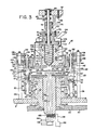
- the molding machine shown in Figures 1, 5 and 6 is conveiently used in this invention.
- the molding machine 12 is mounted above the turret 24 of the molding section of the closure conveying means so that it can rotate together with the turret 24, as in the case of the relation between the extruder 10 and the turret 20 of the closure conveying means 6, although no detail of the mounting mechanism is shown in the drawing.
- the turret 24 of the closure conveying means 6 in the molding section is rotatably mounted on the base stand 2 as in the case of the main body portion 32 of the turret 20 in the stock feeding section, and includes a main body portion 192 (only a part of its peripheral edge is shown in Figure 5) adapted to be driven at a suitable speed in a predetermined direction by a suitable drive source (not shown) such as an electric motor through a suitable power transmissior mechanism (not shown).
- a suitable drive source such as an electric motor
- a suitable power transmissior mechanism not shown
- To the main body portion 192 is secured a turret plate 194, similar to the turret plate 52 in the turret 20, which is a known annular turret plate having a plurality of substantially semicircular closure receivers spaced at equal intervals along the peripheral edge.
- the main body 192 has integrally formed therein an annular projection 196 extending substantially horizontally beneath the turret plate 194 and further extending downwardly in the perpendicular direction.
- annular projection 196 extending substantially horizontally beneath the turret plate 194 and further extending downwardly in the perpendicular direction.
- annular member 200 To the bottom of such an annular projection 196 is fixed an annular member 200 by a suitable means such as bolts 198, and a circulating space 202 through which a cooling medium, preferably water, is circulated is defined between the undersurface of the annular projection 196 and the annular member 200.
- the cooling medium is fed from a supply conduit 204 (see Figure 1) to the circulating space 202 through a flow-in passage (not shown) disposed within the main body 192, and is discharged from a flow-out passage (not shown) disposed within the main body 192 through a discharge conduit 206 (see Figure 1). Furthermore, an annular inside stripper member 208 and an annular outside stripper member 210 are secured to the main body portion 192 at a position above the top surface of the horizontal portion of the annular projection 196 spaced a predetermined distance (slightly larger than the height of the closure).
- these stripper members208 and 210 come into engagement with the upper end of the closure 4 to prevent the closure 4 from rising together with a molding device (to be described hereinbelow) of the molding machine 12 when the molding device is caused to descend in the perpendicular direction and molds the liner stock in the closure 4 placed in a closure receiver of the turret plate and supported on the horizontal portion of the annular projection 196.
- each of the molding tools devices has a sliding member 214 which is mounted slidably in the perpendicular direction on the main body portion 192 of the turret 24 or on a suitable member secured to the main body portion 192.
- the sliding member 214 has provided at its lower portion two annular shoulder portions 216 and 218 facing downward in the perpendicular direction and a central screw hole 220.
- the upper end portion of a central member 222 is screwed with the central screw hole 220 of the sliding member 214.
- the central member 222 includes an upper portion 224 having its outside surface threaded for screwing with the central screw hole 220, a circular-cylindrical lower portion 226 having a predetermined outside diameter, and a flange 230 having a plurality of recesses 228 positioned between the upper portion 224 and the lower portion 226 and spaced from each other in the circumferential direction.
- around the lower end portion of the sliding member 214 is slidably fitted idly an annular member 234 having a plurality of projections 232 projecting downwardly in the perpendicular direction.
- the projections 232 of the annular member 234 are positioned so that they respectively match a plurality of recesses 228 formed at the flange portion 230 of the central member 222.
- a spring 236 which elastically urges the annular member 234 downwardly in the perpendicular direction.
- a molding tool 238 is fitted around the circular cylindrical lower portion 226 of the central member 222 in a manner such that it can freely slide with respect to the lower portion 226.
- the lower end surface of the molding tool 238 to be engaged with the heat-melted liner stock 240 positioned at a predetermined locality in the closure 4 by the extruder 10 as described hereinabove is shaped corresponding to the desired shape of the liner to be finally fcrmed in the closure 40
- the molding tool 238 has formed therein an annular circulating space 242 through which a cooling medium, preferably water, is to be circulated.
- the cooling medium is introduced from a suitable supply conduit (for example, it may be the supply condit 204 shown in Figure 1) into the circulating space 242 through a flow-in passage 244 formed in the sliding member 214 and a flow-in conduit 246 communicating with the flow-in passage 244, and is discharged from a suitable discharge conduit (for example, it may be the discharge conduit 206 shown in Figure 1) through a flow-out conduit 248 and a flow-out passage 250 formed in the sliding member 214.
- a generally substantially cylindrical sleeve 252 is slidably fitted exteriorly of the molding tool 238 and the flange portion 230 of the central member 222.
- the outside diameter of the lower portion of the sleeve 252 should be substantial equal to, or slightly smaller than, the inside diameter of the closure 4.
- a stop ring 254 which abuts the upper surface of the flange portion 230 of the central member 222 to restrict the down-ward movement of the sleeve 252 with respect to the central member 222.
- An annular shoulder portion 256 is formed on the inside of the sleeve 252 at its middle portion.
- the shoulder portion 256 comes into engagement with the undersurface of the annular flange 258 formed at the upper end portion of the molding tool 238 to restrict the downward movement of the molding tool 238 with respect to the sleeve 252.
- a spring 260 which elastically urges the sleeve 252 downwardly in the perpendicular direction so that the stop ring 254 fixed to the sleeve 252 abuts the top surface of the flange portion 230 of the central member 2220
- the molding device 212 further includes a suitable lift mechanism which moves the sliding member 214 of the molding device 212 the central member 222, annular member 234 and molding tool 238 amounted on the molding device 212, and the sleeve 252 upwardly and downwardly in the perpendicular direction as prescribed, when the turret 24 in the molding .
- the lift mechanism may be a mechanism similar to a mechanism composed of the annular cam groove 140 and the cooperating follower roller 132 for moving the shutoff device 126 of the extruder 10 upwardly and downwardly, and therefore, it may be a mechanism constructed of an annular cam groove fixed to the base stand 2 and a follower roller mounted on the upper end portion of the sliding member 214 and cooperating with the annular cam groove upon engagement therewith.
- Such a lift mechanism gradually causes the molding device 212 to descend to the descended position shown in Figure 5 from the lifted position at which the lower end of the lower portion 226 of the central member 222, the lower end of the molding tool 238 and the lower end of the sleeve 252 are somewhat above the stripper members 208 and 210 of the turret 24 in the molding section, while the molding device 212, incident to the rotation of the turret 24, move from the position F in Figure 2-a to the position G in Figure 2-a. While the molding device 212 moves from the position G to the position H shown in Figure 2-a, the lift mechanism holds the molding device 212 in the aforesaid discended position.
- the lift mechanism gradually lifts the molding device 212 from the aforesaid descended position to the lifted position.
- the lift mechanism holds the molding device 212 at the lifted position while the molding device 212 moves from the position I to the position F shown in Figure 2-a.
- the shapes of the lower end surface of the molding tool 238 and the lower end surface of the sleeve 252, therefore the shape of the liner to be formed may be any desired one corresponding to the opening end (not shown) of a container such as a bottle or can to which the closure 4 is to be applied.
- the entire undersurface of the circular-cylindrical lower portion 226 of the central member 222 comes into engagement with the central part of the central panel portion of the closure and therefore, the liner stock does not flow at all to the central part of the central panel portion. If desired, however, some of the liner stock may be permitted to flow to the central part of the central panel portion of the closure at the time of molding.
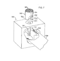
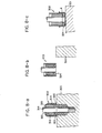
- Figures 7 and 8-a to 8-c show an extruder 300 for extruding a molten liner stock in annular form and a liner stock conveying means 302 for conveying the liner stock extruded from the extruder 300 to a closure and positioning it at a predetermined locality in the closure, which can be used instead of the extruder 10 illustrated in Figures 3 and 40
- the extruder shown in Figure 7 only extrudes the molten liner stock into annular form, and the liner stock extruded from the extruder 300 is conveyed to the inside of the closure 4 by the liner stock conveying means 302 and positioned at a predetermined location.
- the extruder 300 disposed, for example, at the site spaced apart from the turret 20 in the stock feeding section of the closure conveying mechanism 6 of the apparatus shown in Figure 1 is of substantially the same structure as an ordianry extruder except that an extrusion opening 304 preferably directed upwardly in the perpendicular direction is of an annular shape.
- the extruder 300 includes therein an extruder screw 306 (only a part of its tip portion is shown in Figure 7), a heat-melting section 308 and an extrusion opening 304 for extruding the liner stock molten at the heat-melting section 308.
- the extrusion opening 304 is located at an exit end of an extrusion passage 312 having an annular cross section and defined by a hole having a circular cross section and a circular-cylindrical core 310 provide coaxially with, and centrally of, the hole, and has the same annular cross sectional shape as the extrusion passage 3120
- the liner stock conveying means 302 may be of any suitable types which can cut off the molten liner stock extruded from the extrusion opening 304 of the extruder 300 from the extrusion opening 304, convey it to the inside of the closure 4 (see Figure 8-c), and position it at a predetermined location in the closure 4.
- the closure 4 see Figure 8-c
- it is of the structure shown in Figure 7.
- the liner stock conveying means 302 includes a cylindrical outside member 314 disposed con- coaxially, a circular-cylindrical central member 316, and disposed between these an annular intermediate member 318 (Figure 7 and Figures 8-a to 8-c show only the lower end portion of these members), the three members being provided coaxially.
- These three members as will be described in detail hereinbelow are moved integrally by a suitable transfer means (not shown), and the intermediate member 318 is caused to ascend and descend in the perpendicular direction with respect to the outside member 314 and the central member 316 by a suitable actuating means (not shown).
- the intermediate member 318 has formed therein one or a plurality (four in the drawing) of through-holes 322 which communicate with a suitable vacuum supplying means (not shown) through a control valve (not shown).
- the cut-off Ininer stock 324 is held in the recess 320 without dropping.
- the liner stock conveying means 302 having the liner stock 324 stored therein is moved to a position above the closure 4 which is being conveyed by the turret 20 in the stock feeding section of the closure conveying means 6, and is moved synchronously with the closure 4 along the moving path of the closure 4, and simultaneously caused to descend a predetermined distance in the perpendicular direction.
- the liner stock conveying means 302 is inserted in the closure 4 as shown in Figure 8-c, and the lower end of the outside member 314 and the lower end of the central member 316 are brought to a position above the central panel portion of the closure 4 through a distance substantially equal to, or slightly larger than, the depth of the recess 320, i.e. the thickness of the liner stock accommodate therein.
- the supply of vacuum to the liner stock accom modation recess 320 is stopped and the recess 320 is caused to communicate with the outer atmosphere via the through-holes 3220
- the intermediate member 318 is caused to descend with respect to the outside member 314 and the central member 316 so that its lower end is located on the same plane as the lower ends of the central member 316 and the outside member 3140
- the liner stock 324 stored in the recess 320 is discharged from it, and transferred to the inside of the closure 4, whereby the annular molten liner stock 324 is positioned at a predetermined location in the closure 40
- the intermediate member 318 is lifted to the original position, and the outside member 314, the central member 316 and the intermediate member 318 are lifted integrally, and further returned to a position above the extrusion opening 304 of the extruder 300. Then, the above operation is repeated.
- the closure in which the molten liner stock has been positioned in a predetermined location is conveyed to the molding section by the closure conveying means 6, and the liner stock 324 is molded into the desired shape by the action of a suitable molding machine, such as molding machine 12 described hereinabove, while it is in the molten state.
- a suitable molding machine such as molding machine 12 described hereinabove
Landscapes
- Engineering & Computer Science (AREA)
- Mechanical Engineering (AREA)
- Chemical & Material Sciences (AREA)
- Composite Materials (AREA)
- Robotics (AREA)
- Extrusion Moulding Of Plastics Or The Like (AREA)
- Casting Or Compression Moulding Of Plastics Or The Like (AREA)
- Shaping Of Tube Ends By Bending Or Straightening (AREA)
- Lining Or Joining Of Plastics Or The Like (AREA)
- Closures For Containers (AREA)
Applications Claiming Priority (2)
| Application Number | Priority Date | Filing Date | Title |
|---|---|---|---|
| JP14993778A JPS5577523A (en) | 1978-12-06 | 1978-12-06 | Method of and apparatus for forming liner in cover for vessel |
| JP149937/78 | 1978-12-06 |
Publications (2)
| Publication Number | Publication Date |
|---|---|
| EP0012314A1 true EP0012314A1 (fr) | 1980-06-25 |
| EP0012314B1 EP0012314B1 (fr) | 1983-03-09 |
Family
ID=15485816
Family Applications (1)
| Application Number | Title | Priority Date | Filing Date |
|---|---|---|---|
| EP79104847A Expired EP0012314B1 (fr) | 1978-12-06 | 1979-12-03 | Procédé et dispositif d'application d'une garniture dans une fermeture de récipient |
Country Status (8)
| Country | Link |
|---|---|
| EP (1) | EP0012314B1 (fr) |
| JP (1) | JPS5577523A (fr) |
| AU (1) | AU518389B2 (fr) |
| CA (1) | CA1147516A (fr) |
| DE (1) | DE2965009D1 (fr) |
| DK (1) | DK160237C (fr) |
| ES (1) | ES486607A0 (fr) |
| NZ (1) | NZ192221A (fr) |
Cited By (7)
| Publication number | Priority date | Publication date | Assignee | Title |
|---|---|---|---|---|
| EP0021691A1 (fr) * | 1979-06-08 | 1981-01-07 | Japan Crown Cork Co. Ltd. | Procédé de fabrication d'obturateurs de récipients munis de garnitures et bouteilles fermées à l'aide de ces obturateurs |
| EP0037651A3 (en) * | 1980-03-21 | 1982-08-11 | Japan Crown Cork Co. Ltd. | Molding device for molding a liner on the inside surface of the top panel of a container closure shell |
| EP0207385A3 (en) * | 1985-06-24 | 1988-09-07 | Sacmi Cooperativa Meccanici Imola Soc. Coop. A Resp. Lim. | Apparatus for the application of a gasket inside closures comprising a cup, such as a screw-on and crown caps |
| WO1995007174A1 (fr) * | 1993-09-04 | 1995-03-16 | Basf Lacke + Farben Ag | Procede et dispositif d'introduction d'un materiau d'etancheite dans des fermetures demi-tour a ergots |
| EP0838326A1 (fr) * | 1996-10-24 | 1998-04-29 | SACMI COOPERATIVA MECCANICI IMOLA S.c.r.l. | Appareil pour mouler un joint d'étanchéité plastique à l'intérieur d'une capsule pour fermer un récipient |
| WO2012139887A1 (fr) | 2011-04-11 | 2012-10-18 | Umicore Building Products France | Bande de finition multicouches |
| CN103568179A (zh) * | 2012-07-20 | 2014-02-12 | 蔡鸿森 | 罐盖密封胶层制造方法 |
Families Citing this family (1)
| Publication number | Priority date | Publication date | Assignee | Title |
|---|---|---|---|---|
| JP4571735B2 (ja) * | 2000-09-13 | 2010-10-27 | 日本クラウンコルク株式会社 | 容器蓋シェル内にライナーを形成する方法 |
Citations (13)
| Publication number | Priority date | Publication date | Assignee | Title |
|---|---|---|---|---|
| US1451470A (en) * | 1920-10-18 | 1923-04-10 | Willis J Peelle | Means for forming and securing gaskets to jar covers |
| US2391341A (en) * | 1943-11-23 | 1945-12-18 | Continental Can Co | Machine for applying sealing compound to container ends |
| US3038507A (en) * | 1958-05-19 | 1962-06-12 | Watts Electric & Mfg Co | Metering device for plastic material |
| US3074810A (en) * | 1959-12-30 | 1963-01-22 | Grace W R & Co | Method and apparatus for lining container closures |
| GB1043881A (en) * | 1962-04-04 | 1966-09-28 | Owens Illinois Inc | Apparatus for bonding sealing rings to closure cap shells |
| US3343211A (en) * | 1966-10-12 | 1967-09-26 | Rosen And Strickman | Apparatus for forming ring-shaped extrudates |
| US3407442A (en) * | 1966-09-01 | 1968-10-29 | Continental Can Co | Machine for in-place molding of cap gaskets |
| US3635619A (en) * | 1969-03-24 | 1972-01-18 | Continental Can Co | Electrically heated compound molding machine |
| FR2227999A1 (fr) * | 1973-05-01 | 1974-11-29 | Broken Hill Pty Co Ltd | |
| US3873258A (en) * | 1971-09-02 | 1975-03-25 | Ball Corp | Apparatus for applying a sealing gasket to a surface |
| FR2312353A1 (fr) * | 1975-05-30 | 1976-12-24 | Gen Electric | Dispositif d'application a buse pour la formation sur place d'une garniture |
| US4010703A (en) * | 1975-12-17 | 1977-03-08 | The Continental Group, Inc. | End lining with hot melt |
| US4070885A (en) * | 1974-05-21 | 1978-01-31 | Toyo Seikan Kaisha Limited | Apparatus for simultaneously deforming and coating |
-
1978
- 1978-12-06 JP JP14993778A patent/JPS5577523A/ja active Granted
-
1979
- 1979-11-21 CA CA000340345A patent/CA1147516A/fr not_active Expired
- 1979-11-23 NZ NZ192221A patent/NZ192221A/en unknown
- 1979-11-28 AU AU53269/79A patent/AU518389B2/en not_active Ceased
- 1979-12-03 EP EP79104847A patent/EP0012314B1/fr not_active Expired
- 1979-12-03 DE DE7979104847T patent/DE2965009D1/de not_active Expired
- 1979-12-05 ES ES486607A patent/ES486607A0/es active Granted
- 1979-12-05 DK DK518079A patent/DK160237C/da not_active IP Right Cessation
Patent Citations (13)
| Publication number | Priority date | Publication date | Assignee | Title |
|---|---|---|---|---|
| US1451470A (en) * | 1920-10-18 | 1923-04-10 | Willis J Peelle | Means for forming and securing gaskets to jar covers |
| US2391341A (en) * | 1943-11-23 | 1945-12-18 | Continental Can Co | Machine for applying sealing compound to container ends |
| US3038507A (en) * | 1958-05-19 | 1962-06-12 | Watts Electric & Mfg Co | Metering device for plastic material |
| US3074810A (en) * | 1959-12-30 | 1963-01-22 | Grace W R & Co | Method and apparatus for lining container closures |
| GB1043881A (en) * | 1962-04-04 | 1966-09-28 | Owens Illinois Inc | Apparatus for bonding sealing rings to closure cap shells |
| US3407442A (en) * | 1966-09-01 | 1968-10-29 | Continental Can Co | Machine for in-place molding of cap gaskets |
| US3343211A (en) * | 1966-10-12 | 1967-09-26 | Rosen And Strickman | Apparatus for forming ring-shaped extrudates |
| US3635619A (en) * | 1969-03-24 | 1972-01-18 | Continental Can Co | Electrically heated compound molding machine |
| US3873258A (en) * | 1971-09-02 | 1975-03-25 | Ball Corp | Apparatus for applying a sealing gasket to a surface |
| FR2227999A1 (fr) * | 1973-05-01 | 1974-11-29 | Broken Hill Pty Co Ltd | |
| US4070885A (en) * | 1974-05-21 | 1978-01-31 | Toyo Seikan Kaisha Limited | Apparatus for simultaneously deforming and coating |
| FR2312353A1 (fr) * | 1975-05-30 | 1976-12-24 | Gen Electric | Dispositif d'application a buse pour la formation sur place d'une garniture |
| US4010703A (en) * | 1975-12-17 | 1977-03-08 | The Continental Group, Inc. | End lining with hot melt |
Cited By (10)
| Publication number | Priority date | Publication date | Assignee | Title |
|---|---|---|---|---|
| EP0021691A1 (fr) * | 1979-06-08 | 1981-01-07 | Japan Crown Cork Co. Ltd. | Procédé de fabrication d'obturateurs de récipients munis de garnitures et bouteilles fermées à l'aide de ces obturateurs |
| EP0037651A3 (en) * | 1980-03-21 | 1982-08-11 | Japan Crown Cork Co. Ltd. | Molding device for molding a liner on the inside surface of the top panel of a container closure shell |
| EP0207385A3 (en) * | 1985-06-24 | 1988-09-07 | Sacmi Cooperativa Meccanici Imola Soc. Coop. A Resp. Lim. | Apparatus for the application of a gasket inside closures comprising a cup, such as a screw-on and crown caps |
| WO1995007174A1 (fr) * | 1993-09-04 | 1995-03-16 | Basf Lacke + Farben Ag | Procede et dispositif d'introduction d'un materiau d'etancheite dans des fermetures demi-tour a ergots |
| US5763004A (en) * | 1993-09-04 | 1998-06-09 | Basf Lacke + Farben, Ag | Appliance and process for introducing sealing compound into lug caps |
| EP0838326A1 (fr) * | 1996-10-24 | 1998-04-29 | SACMI COOPERATIVA MECCANICI IMOLA S.c.r.l. | Appareil pour mouler un joint d'étanchéité plastique à l'intérieur d'une capsule pour fermer un récipient |
| US6007315A (en) * | 1996-10-24 | 1999-12-28 | Sacmi Cooperative Meccanici Imola S.C.R.L. | Apparatus for molding a plastic seal inside a closure for closing a container |
| WO2012139887A1 (fr) | 2011-04-11 | 2012-10-18 | Umicore Building Products France | Bande de finition multicouches |
| CN103568179A (zh) * | 2012-07-20 | 2014-02-12 | 蔡鸿森 | 罐盖密封胶层制造方法 |
| CN103568179B (zh) * | 2012-07-20 | 2016-03-30 | 蔡鸿森 | 罐盖密封胶层制造方法 |
Also Published As
| Publication number | Publication date |
|---|---|
| ES8101983A1 (es) | 1980-12-16 |
| DE2965009D1 (en) | 1983-04-14 |
| JPS5577523A (en) | 1980-06-11 |
| ES486607A0 (es) | 1980-12-16 |
| AU518389B2 (en) | 1981-10-01 |
| DK160237C (da) | 1991-07-29 |
| EP0012314B1 (fr) | 1983-03-09 |
| JPS6113966B2 (fr) | 1986-04-16 |
| NZ192221A (en) | 1984-02-03 |
| AU5326979A (en) | 1980-06-12 |
| DK160237B (da) | 1991-02-18 |
| CA1147516A (fr) | 1983-06-07 |
| DK518079A (da) | 1980-06-07 |
Similar Documents
| Publication | Publication Date | Title |
|---|---|---|
| US4412797A (en) | Apparatus for forming a liner in a container closure | |
| US4776782A (en) | Rotational plastic compression molding apparatus | |
| US4979282A (en) | Apparatus for the application of a gasket inside closures comprising a cup, such as screw-on and crown caps | |
| RU2556674C2 (ru) | Установка для производства пластиковых контейнеров | |
| US4640673A (en) | Compression molding apparatus | |
| US4117050A (en) | Method for heating and blow molding plaster parisons | |
| EP0012314B1 (fr) | Procédé et dispositif d'application d'une garniture dans une fermeture de récipient | |
| US3661489A (en) | Apparatus for forming containers by molding | |
| EP0462513B1 (fr) | Dispositif pour formage d'une couche annulaire | |
| US20110100994A1 (en) | Apparatuses and methods for making seal rings for caps, and thus obtained seal rings | |
| US5190769A (en) | Apparatus for forming annular liner | |
| JPS6049573B2 (ja) | 吹込み成形装置 | |
| US5035594A (en) | Compression molding apparatus | |
| CN111844692A (zh) | 一种塑料瓶连续生产灌装设备 | |
| US3212131A (en) | Plastic metering means | |
| KR830002510B1 (ko) | 용기 뚜껑내에 라이너를 형성시키기 위한 방법 | |
| US20080277830A1 (en) | Apparatus for Transferring Doses of Plastics to the Dies of a Compression Moulding Machine | |
| US5118273A (en) | Compression molding apparatus | |
| US3407442A (en) | Machine for in-place molding of cap gaskets | |
| US3741553A (en) | Method and apparatus for forming containers by blow-molding | |
| EP1551610B1 (fr) | Dispositif de formation de quantites predeterminees de matiere synthetique | |
| JP2952693B2 (ja) | 環状ライナー成形装置 | |
| US3360821A (en) | Elastic melt extruder with peripheral feed | |
| JP3170731B2 (ja) | 容器蓋シエル内に合成樹脂製ライナーを配設する方法及び装置 | |
| JPH0156642B2 (fr) |
Legal Events
| Date | Code | Title | Description |
|---|---|---|---|
| PUAI | Public reference made under article 153(3) epc to a published international application that has entered the european phase |
Free format text: ORIGINAL CODE: 0009012 |
|
| AK | Designated contracting states |
Designated state(s): BE CH DE FR GB IT NL SE |
|
| 17P | Request for examination filed | ||
| ITF | It: translation for a ep patent filed | ||
| GRAA | (expected) grant |
Free format text: ORIGINAL CODE: 0009210 |
|
| AK | Designated contracting states |
Designated state(s): BE CH DE FR GB IT NL SE |
|
| ET | Fr: translation filed | ||
| REF | Corresponds to: |
Ref document number: 2965009 Country of ref document: DE Date of ref document: 19830414 |
|
| ITTA | It: last paid annual fee | ||
| PGFP | Annual fee paid to national office [announced via postgrant information from national office to epo] |
Ref country code: SE Payment date: 19931027 Year of fee payment: 15 |
|
| PGFP | Annual fee paid to national office [announced via postgrant information from national office to epo] |
Ref country code: CH Payment date: 19931028 Year of fee payment: 15 |
|
| PGFP | Annual fee paid to national office [announced via postgrant information from national office to epo] |
Ref country code: BE Payment date: 19931103 Year of fee payment: 15 |
|
| PGFP | Annual fee paid to national office [announced via postgrant information from national office to epo] |
Ref country code: FR Payment date: 19931118 Year of fee payment: 15 |
|
| PGFP | Annual fee paid to national office [announced via postgrant information from national office to epo] |
Ref country code: GB Payment date: 19931123 Year of fee payment: 15 |
|
| PGFP | Annual fee paid to national office [announced via postgrant information from national office to epo] |
Ref country code: NL Payment date: 19931231 Year of fee payment: 15 |
|
| PGFP | Annual fee paid to national office [announced via postgrant information from national office to epo] |
Ref country code: DE Payment date: 19940228 Year of fee payment: 15 |
|
| PG25 | Lapsed in a contracting state [announced via postgrant information from national office to epo] |
Ref country code: GB Effective date: 19941203 |
|
| PG25 | Lapsed in a contracting state [announced via postgrant information from national office to epo] |
Ref country code: SE Effective date: 19941204 |
|
| PG25 | Lapsed in a contracting state [announced via postgrant information from national office to epo] |
Ref country code: CH Effective date: 19941231 Ref country code: BE Effective date: 19941231 |
|
| EAL | Se: european patent in force in sweden |
Ref document number: 79104847.3 |
|
| BERE | Be: lapsed |
Owner name: JAPAN CROWN CORK CO. LTD. Effective date: 19941231 |
|
| PG25 | Lapsed in a contracting state [announced via postgrant information from national office to epo] |
Ref country code: NL Effective date: 19950701 |
|
| GBPC | Gb: european patent ceased through non-payment of renewal fee |
Effective date: 19941203 |
|
| PG25 | Lapsed in a contracting state [announced via postgrant information from national office to epo] |
Ref country code: FR Effective date: 19950831 |
|
| REG | Reference to a national code |
Ref country code: CH Ref legal event code: PL |
|
| NLV4 | Nl: lapsed or anulled due to non-payment of the annual fee |
Effective date: 19950701 |
|
| PG25 | Lapsed in a contracting state [announced via postgrant information from national office to epo] |
Ref country code: DE Effective date: 19950901 |
|
| EUG | Se: european patent has lapsed |
Ref document number: 79104847.3 |
|
| REG | Reference to a national code |
Ref country code: FR Ref legal event code: ST |
|
| PLBE | No opposition filed within time limit |
Free format text: ORIGINAL CODE: 0009261 |
|
| STAA | Information on the status of an ep patent application or granted ep patent |
Free format text: STATUS: NO OPPOSITION FILED WITHIN TIME LIMIT |