EP0012814A1 - Disposition de contre-électrode d'un dispositif d'affichage électrochromique - Google Patents
Disposition de contre-électrode d'un dispositif d'affichage électrochromique Download PDFInfo
- Publication number
- EP0012814A1 EP0012814A1 EP79104228A EP79104228A EP0012814A1 EP 0012814 A1 EP0012814 A1 EP 0012814A1 EP 79104228 A EP79104228 A EP 79104228A EP 79104228 A EP79104228 A EP 79104228A EP 0012814 A1 EP0012814 A1 EP 0012814A1
- Authority
- EP
- European Patent Office
- Prior art keywords
- electrode
- counter electrode
- donor
- potential
- counter
- Prior art date
- Legal status (The legal status is an assumption and is not a legal conclusion. Google has not performed a legal analysis and makes no representation as to the accuracy of the status listed.)
- Granted
Links
- BASFCYQUMIYNBI-UHFFFAOYSA-N platinum Chemical compound [Pt] BASFCYQUMIYNBI-UHFFFAOYSA-N 0.000 claims abstract description 8
- 239000003792 electrolyte Substances 0.000 claims description 7
- 239000000463 material Substances 0.000 description 8
- 239000004020 conductor Substances 0.000 description 6
- 239000000758 substrate Substances 0.000 description 5
- 230000008021 deposition Effects 0.000 description 3
- 230000000694 effects Effects 0.000 description 3
- KDLHZDBZIXYQEI-UHFFFAOYSA-N Palladium Chemical compound [Pd] KDLHZDBZIXYQEI-UHFFFAOYSA-N 0.000 description 2
- 125000000129 anionic group Chemical group 0.000 description 2
- 238000010586 diagram Methods 0.000 description 2
- 230000005518 electrochemistry Effects 0.000 description 2
- JKQOBWVOAYFWKG-UHFFFAOYSA-N molybdenum trioxide Chemical compound O=[Mo](=O)=O JKQOBWVOAYFWKG-UHFFFAOYSA-N 0.000 description 2
- 239000000565 sealant Substances 0.000 description 2
- XOLBLPGZBRYERU-UHFFFAOYSA-N tin dioxide Chemical compound O=[Sn]=O XOLBLPGZBRYERU-UHFFFAOYSA-N 0.000 description 2
- 229910001887 tin oxide Inorganic materials 0.000 description 2
- XJGZGUSMZSXHJI-UHFFFAOYSA-N 1-heptyl-4-(1-heptylpyridin-1-ium-4-yl)pyridin-1-ium Chemical compound C1=C[N+](CCCCCCC)=CC=C1C1=CC=[N+](CCCCCCC)C=C1 XJGZGUSMZSXHJI-UHFFFAOYSA-N 0.000 description 1
- DZFLWZSJWNYVEU-UHFFFAOYSA-N P(O)(O)(O)=O.[PH2](=O)O Chemical compound P(O)(O)(O)=O.[PH2](=O)O DZFLWZSJWNYVEU-UHFFFAOYSA-N 0.000 description 1
- -1 WO3 and MoO3 Chemical class 0.000 description 1
- QVGXLLKOCUKJST-UHFFFAOYSA-N atomic oxygen Chemical compound [O] QVGXLLKOCUKJST-UHFFFAOYSA-N 0.000 description 1
- 238000006243 chemical reaction Methods 0.000 description 1
- 239000000470 constituent Substances 0.000 description 1
- 229910010272 inorganic material Inorganic materials 0.000 description 1
- 239000011147 inorganic material Substances 0.000 description 1
- 239000013546 insoluble monolayer Substances 0.000 description 1
- 239000003014 ion exchange membrane Substances 0.000 description 1
- 229910052741 iridium Inorganic materials 0.000 description 1
- GKOZUEZYRPOHIO-UHFFFAOYSA-N iridium atom Chemical compound [Ir] GKOZUEZYRPOHIO-UHFFFAOYSA-N 0.000 description 1
- 239000011244 liquid electrolyte Substances 0.000 description 1
- 239000011159 matrix material Substances 0.000 description 1
- 239000012528 membrane Substances 0.000 description 1
- 238000000034 method Methods 0.000 description 1
- 229910052760 oxygen Inorganic materials 0.000 description 1
- 239000001301 oxygen Substances 0.000 description 1
- 229910052763 palladium Inorganic materials 0.000 description 1
- 150000005839 radical cations Chemical class 0.000 description 1
- 238000006479 redox reaction Methods 0.000 description 1
- 230000002441 reversible effect Effects 0.000 description 1
- 229910052703 rhodium Inorganic materials 0.000 description 1
- 239000010948 rhodium Substances 0.000 description 1
- MHOVAHRLVXNVSD-UHFFFAOYSA-N rhodium atom Chemical compound [Rh] MHOVAHRLVXNVSD-UHFFFAOYSA-N 0.000 description 1
- 239000004065 semiconductor Substances 0.000 description 1
- 150000003623 transition metal compounds Chemical class 0.000 description 1
- 210000000707 wrist Anatomy 0.000 description 1
Images
Classifications
-
- G—PHYSICS
- G02—OPTICS
- G02F—OPTICAL DEVICES OR ARRANGEMENTS FOR THE CONTROL OF LIGHT BY MODIFICATION OF THE OPTICAL PROPERTIES OF THE MEDIA OF THE ELEMENTS INVOLVED THEREIN; NON-LINEAR OPTICS; FREQUENCY-CHANGING OF LIGHT; OPTICAL LOGIC ELEMENTS; OPTICAL ANALOGUE/DIGITAL CONVERTERS
- G02F1/00—Devices or arrangements for the control of the intensity, colour, phase, polarisation or direction of light arriving from an independent light source, e.g. switching, gating or modulating; Non-linear optics
- G02F1/01—Devices or arrangements for the control of the intensity, colour, phase, polarisation or direction of light arriving from an independent light source, e.g. switching, gating or modulating; Non-linear optics for the control of the intensity, phase, polarisation or colour
- G02F1/15—Devices or arrangements for the control of the intensity, colour, phase, polarisation or direction of light arriving from an independent light source, e.g. switching, gating or modulating; Non-linear optics for the control of the intensity, phase, polarisation or colour based on an electrochromic effect
- G02F1/163—Operation of electrochromic cells, e.g. electrodeposition cells; Circuit arrangements therefor
-
- G—PHYSICS
- G02—OPTICS
- G02F—OPTICAL DEVICES OR ARRANGEMENTS FOR THE CONTROL OF LIGHT BY MODIFICATION OF THE OPTICAL PROPERTIES OF THE MEDIA OF THE ELEMENTS INVOLVED THEREIN; NON-LINEAR OPTICS; FREQUENCY-CHANGING OF LIGHT; OPTICAL LOGIC ELEMENTS; OPTICAL ANALOGUE/DIGITAL CONVERTERS
- G02F2201/00—Constructional arrangements not provided for in groups G02F1/00 - G02F7/00
- G02F2201/12—Constructional arrangements not provided for in groups G02F1/00 - G02F7/00 electrode
- G02F2201/121—Constructional arrangements not provided for in groups G02F1/00 - G02F7/00 electrode common or background
Definitions
- This invention relates to a counter electrode arrangement of an electrochromic display device.
- an electrochromic display device is a device in which the display effect is achieved as a consequence of a redox reaction.
- One class of such devices uses a liquid electrolyte containing viologen and a suitable anionic material. Upon application of the appropriate potential between a display electrode and the counter electrode, the viologen dication is reduced to the radical cation which: then combines with the anionic material and forms an insoluble coloured film on the display electrode. The process is reversible. Inorganic materials, especially transition metal compounds such as WO 3 and MoO 3 , are also useful.
- a typical electrochromic display device there are a plurality of display electrodes and, usually, a single counter electrode.
- a single counter electrode Although suggestions have been made to provide electrochromic display devices with the display elements at the crosspoints of orthogonal sets of electrodes, the problems of electrochemically.isolating each crosspoint are daunting.
- the potential difference between the counter electrode and each display electrode In order to operate a display device with a single counter electrode efficiently, it is necessary that the potential difference between the counter electrode and each display electrode be substantially the same. Two factors militate against this: potential drop in the electrolyte, and potential drop along the counter electrode itself.
- the device is sufficiently small - for example, a wrist watch display - it is possible to locate the counter elec- trode anywhere in the electrolyte, but if the difference in the distances between the counter electrode and the nearest and most remote display electrodes is large (for example greater than lcm.) the potential drop in the electrolyte may have a significant effect on operation of the device. The effect is most marked in the case of erasure, i.e. removing the deposited material from the display electrodes. If the potentials are chosen to erase completely the remotest display electrode, this can result in nearer electrodes being over-erased, with evolution of oxygen and other undesirable reactions.
- display electrodes are preferably erased by reversing the write (deposition) potential. It is, of course, possible to overcome the problem of different potential drops between counter electrode and different display electrodes by providing different potentials at different display electrodes or at different sets of display electrodes, grouped according to their distance from the counter electrode. However this substantially increases the complexity, cost, and unreliability of the driving circuitry. A better solution would seem to be to provide a counter electrode which is equidistant from all display electrodes.
- Tin oxide or similar transparent conductive materials have been coated on the inner face of the transparent sheet through which the display electrodes are viewed. This arrangement eliminates the problem due to the potential drop in the electrolyte, but due to the resistance of the tin oxide introduces the problem of the different potential drops in the counter electrode between the potential source and th- regions of the counter electrode interacting with different display electrodes.
- Our present invention aims to provide a simpler counter electrode charging system.
- an electrochromic display device includes a counter electrode which, in operation, is maintained charged to a given potential, and a donor electrode which, in operation, transfers charge to the counter electrode, the display device being characterised by a reference electrode, arranged in operation to sense the potential of the counter electrode, and by electric circuit means, responsive to the potential sensed by the reference electrode to cause the donor electrode to transfer charge to the counter electrode so as to maintain the counter electrode at the given potential.
- both the donor and counter electrodes are of a high specific surface area material, preferably platinum black.
- Specific surface area is the proportion of the actual surface area to the plane area bounded by the edges of the electrode.
- a rough material has a high specific surface area.
- the counter electrode may take any of the shapes described in our co-pending application 16208/77, but the invention is not limited to any form of counter electrode.
- the donor electrode may be arranged as a frame about the viewing area of the display device and may be controlled, in response to the potential sensed by the reference electrode, by an arrangement known in electrochemistry as a potentiostat.
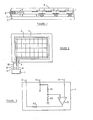
- Figure 1 is a schematic part cross-section of an electrochromic display device according to the invention.
- the device consists of selectively addressible display electrodes 1, a counter electrode 2, a donor electrode 3 and a reference electrode 4.
- the display electrodes 1 are located on a suitable substrate 5, through which lead conductive vias 6 which connect the respective display electrodes 1 to address circuitry (not shown) located in a plane 7.
- the address circuitry is not part of the invention and is conventional.
- the address circuitry may be conductors connecting the respective vias 6 to address gates, or may be semiconductor switches, one to each display electrode 1, arranged in a matrix.
- a donor electrode 3 is located at the periphery of substrate 5, and is preferably made of platinum black. Preferably the donor electrode 3 surrounds area occupied by the display electrodes 1 in the manner of a picture frame.
- a transparent plate 8 supports the counter electrode 2 and, as shown, the reference electrode 4. The plate 8 is hermetically sealed to substrate 5 by any suitable sealant 9. The space between substrate 5 and plate 8 is filled with a suitable electrolyte such as heptyl viologen dihydrogen phosphate-hypophosphite, as disclosed in our co-pending British patent application 45500/77 (UK977-018). For filling the device, a capillary (not shown) is embedded in the sealant 9. The periphery of plate 8 may be opaque to hide the donor electrode 3 and reference electrode 4 from view.
- Figure 2 is a schematic plan view of the device, omitting plate 8 and substrate 5, to show the preferred relative dispositions of the counter electrode 2, the donor electrode 3 and the reference electrode 4, and the electrical connections between these electrodes.
- the counter electrode 2 is of platinum black and is grid shaped, as described in our co-pending application 16208/77 (UK977-001), with a terminal 10 extending out of the display area through a gap in the donor electrode 3. Terminal 10, donor electrode 3 and reference electrode 4 are all connected to a potentiostat 11.
- potentiostat 11 is, by means of reference electrode 4, to sense the potential of counter electrode 2, and to adjust the current between donor electrode 3 and counter electrode 2 to maintain the counter electrode 2 at the required potential.
- a circuit diagram of potentiostat 11 is shown in Figure 3 in which the conductors connecting the potentiostat to the donor electrodes 3, counter electrode 2 and reference electrode 4 are referenced 12, 13 and 14 respectively.
- a source of potential +V is connected to conductor 13 which is also connected to ground through the resistor chain R1, R2.
- the junction of resistors Rl, R2 is connected to the positive input of an operational amplifier 15.
- Conductor 14 from reference electrode 4 is connected to the negative input of the operational amplifier 15, the output of which is connected through a current limiting resistor R3 to conductor 12 and so to the donor electrode 3.
- ⁇ V V.Rl/(Rl+R2)
- the potential of the counter electrode 2 as sensed by reference electrode 4
- current flows at the output of the amplifier so that charge is transferred between the donor electrode 3 and counter electrode 2 until the charge on the counter electrode is sufficient to raise its potential to ⁇ V.
- Typical values for V, Rl, R2 and R3 are 5V, lOKohm, 100Kohm and lKohm respectively.
- the Pt(II) is present as an insoluble monolayer of PtO, thus eliminating the need for a membrane between the donor and counter electrodes.
- platinum black is the preferred constituent of the electrodes other materials can be used, for example, palladium, rhodium or iridium.
Landscapes
- Physics & Mathematics (AREA)
- Nonlinear Science (AREA)
- General Physics & Mathematics (AREA)
- Optics & Photonics (AREA)
- Control Of Indicators Other Than Cathode Ray Tubes (AREA)
- Electrochromic Elements, Electrophoresis, Or Variable Reflection Or Absorption Elements (AREA)
- Devices For Indicating Variable Information By Combining Individual Elements (AREA)
Applications Claiming Priority (2)
| Application Number | Priority Date | Filing Date | Title |
|---|---|---|---|
| GB7949274A GB2038065B (en) | 1978-12-20 | 1978-12-20 | Control of counter electrode potential in electrochromic cell |
| GB4927478 | 1978-12-20 |
Publications (2)
| Publication Number | Publication Date |
|---|---|
| EP0012814A1 true EP0012814A1 (fr) | 1980-07-09 |
| EP0012814B1 EP0012814B1 (fr) | 1983-11-02 |
Family
ID=10501842
Family Applications (1)
| Application Number | Title | Priority Date | Filing Date |
|---|---|---|---|
| EP79104228A Expired EP0012814B1 (fr) | 1978-12-20 | 1979-10-31 | Disposition de contre-électrode d'un dispositif d'affichage électrochromique |
Country Status (5)
| Country | Link |
|---|---|
| US (1) | US4256380A (fr) |
| EP (1) | EP0012814B1 (fr) |
| JP (1) | JPS5587184A (fr) |
| DE (1) | DE2966374D1 (fr) |
| GB (1) | GB2038065B (fr) |
Cited By (1)
| Publication number | Priority date | Publication date | Assignee | Title |
|---|---|---|---|---|
| DE3205056A1 (de) * | 1981-10-28 | 1983-08-18 | SCHÜCO Heinz Schürmann GmbH & Co, 4800 Bielefeld | Fenster oder tuer in rahmenbauweise mit einer durchsichtigen, mehrschichtigen fuellungsplatte und einer verdunklungsvorrichtung |
Families Citing this family (12)
| Publication number | Priority date | Publication date | Assignee | Title |
|---|---|---|---|---|
| JPS5642213A (en) * | 1979-07-17 | 1981-04-20 | Seiko Instr & Electronics Ltd | Electrochromic display device |
| JPS5657097A (en) * | 1979-10-15 | 1981-05-19 | Seiko Instr & Electronics | Method of driving electrochromic display unit |
| JPS56100387A (en) * | 1980-01-14 | 1981-08-12 | Seiko Instr & Electronics Ltd | Electronic watch |
| US4613211A (en) * | 1983-11-21 | 1986-09-23 | Chevron Research Company | Electrochromic devices |
| JPS61147237A (ja) * | 1984-12-20 | 1986-07-04 | Nissan Motor Co Ltd | 透明度可変素子 |
| DE4006947A1 (de) * | 1990-03-06 | 1991-09-12 | Bayerische Motoren Werke Ag | Verfahren und anordnung zum anlegen einer elektrischen betriebsspannung an ein elektrooptisches schichtsystem |
| US5293546A (en) * | 1991-04-17 | 1994-03-08 | Martin Marietta Corporation | Oxide coated metal grid electrode structure in display devices |
| WO1994016356A1 (fr) * | 1993-01-05 | 1994-07-21 | Martin Marietta Corporation | Electrode amelioree pour dispositifs d'affichage |
| CA2220519A1 (fr) * | 1995-05-09 | 1996-11-21 | James P. Coleman | Police de caracteres conductrice |
| HUP9900853A2 (hu) * | 1995-06-07 | 1999-07-28 | Monsanto Co. | Eszköz és eljárás fény modulálására |
| US5877888A (en) * | 1997-06-10 | 1999-03-02 | Monsanto Company | Single and double sided electrochromic displays |
| US12168714B2 (en) | 2020-07-16 | 2024-12-17 | Ambilight Inc. | All-donor black electrochromic polymer and method for preparing same |
Citations (4)
| Publication number | Priority date | Publication date | Assignee | Title |
|---|---|---|---|---|
| US3961842A (en) * | 1974-09-20 | 1976-06-08 | Texas Instruments Incorporated | Regenerating electrode for electrochromic display cell |
| FR2363852A1 (fr) * | 1976-09-02 | 1978-03-31 | Matsushita Electric Industrial Co Ltd | Dispositif d'affichage electrochromogene |
| FR2388358A1 (fr) * | 1977-04-19 | 1978-11-17 | Ibm | Dispositif d'affichage electrochromique |
| FR2388359A1 (fr) * | 1977-04-19 | 1978-11-17 | Ibm | Dispositif d'affichage electrochromique |
Family Cites Families (3)
| Publication number | Priority date | Publication date | Assignee | Title |
|---|---|---|---|---|
| US4147416A (en) * | 1976-03-30 | 1979-04-03 | Citizen Watch Co., Ltd. | Electrochromic display device |
| GB1558014A (en) * | 1976-08-31 | 1979-12-19 | Xerox Corp | Method and apparatus for forming visible images in electrochromic materials |
| US4215918A (en) * | 1978-09-13 | 1980-08-05 | Board of Regents, State of Florida, Tallahassee, Florida, for the use and benefit of the University of Florida | Electrochromic display device |
-
1978
- 1978-12-20 GB GB7949274A patent/GB2038065B/en not_active Expired
-
1979
- 1979-09-20 US US06/077,425 patent/US4256380A/en not_active Expired - Lifetime
- 1979-10-31 DE DE7979104228T patent/DE2966374D1/de not_active Expired
- 1979-10-31 EP EP79104228A patent/EP0012814B1/fr not_active Expired
- 1979-11-09 JP JP14450979A patent/JPS5587184A/ja active Granted
Patent Citations (6)
| Publication number | Priority date | Publication date | Assignee | Title |
|---|---|---|---|---|
| US3961842A (en) * | 1974-09-20 | 1976-06-08 | Texas Instruments Incorporated | Regenerating electrode for electrochromic display cell |
| FR2363852A1 (fr) * | 1976-09-02 | 1978-03-31 | Matsushita Electric Industrial Co Ltd | Dispositif d'affichage electrochromogene |
| FR2388358A1 (fr) * | 1977-04-19 | 1978-11-17 | Ibm | Dispositif d'affichage electrochromique |
| FR2388359A1 (fr) * | 1977-04-19 | 1978-11-17 | Ibm | Dispositif d'affichage electrochromique |
| US4167309A (en) * | 1977-04-19 | 1979-09-11 | International Business Machines Corporation | Electrochromic display device |
| US4167308A (en) * | 1977-04-19 | 1979-09-11 | International Business Machines Corporation | Electrochromic display device |
Non-Patent Citations (1)
| Title |
|---|
| PROCEEDINGS OF THE S.I.D. Vol. 16, No. 3, Third Quarter 1975 Los Angeles, US I.F. CHANG "Performance characteristics of electrochromic display", pages 168-177. * Page 169-170, paragraphe III; figure 1 * * |
Cited By (2)
| Publication number | Priority date | Publication date | Assignee | Title |
|---|---|---|---|---|
| DE3205056A1 (de) * | 1981-10-28 | 1983-08-18 | SCHÜCO Heinz Schürmann GmbH & Co, 4800 Bielefeld | Fenster oder tuer in rahmenbauweise mit einer durchsichtigen, mehrschichtigen fuellungsplatte und einer verdunklungsvorrichtung |
| EP0086873A1 (fr) * | 1981-10-28 | 1983-08-31 | SCHÜCO Heinz Schürmann GmbH & Co. | Vitre pour une fenêtre ou une porte, comportant un dispositif d'obsurcissement |
Also Published As
| Publication number | Publication date |
|---|---|
| EP0012814B1 (fr) | 1983-11-02 |
| GB2038065A (en) | 1980-07-16 |
| DE2966374D1 (en) | 1983-12-08 |
| US4256380A (en) | 1981-03-17 |
| JPS5587184A (en) | 1980-07-01 |
| GB2038065B (en) | 1982-07-21 |
| JPS6159515B2 (fr) | 1986-12-16 |
Similar Documents
| Publication | Publication Date | Title |
|---|---|---|
| US4256380A (en) | Counter electrode arrangement of an electrochromic display device | |
| US5223823A (en) | Electrophoretic display panel with plural electrically independent anode elements | |
| EP0396247B1 (fr) | Dispositif d'affichage électrophorétique à panneau plat pourvu d'une anode dédoublée | |
| TW360811B (en) | Liquid crystal display device and method for manufacturing the same | |
| JPH09502540A (ja) | 選択的文字アドレス指定可能な電気泳動表示装置パネル | |
| CA1054738A (fr) | Dispositif d'affichage electrochromatique | |
| EP0575475B1 (fr) | Panneau d'affichage electrophoretique pourvu d'un ensemble d'elements d'anode electriquement independants | |
| EP0372356A3 (fr) | Dispositif d'affichage à cristal liquide | |
| US4167308A (en) | Electrochromic display device | |
| EP0607145A4 (fr) | Structure d'electrode destinee a un dispositif d'affichage a electrophoretique. | |
| GB1513999A (en) | Electrochromic display device | |
| US20180138558A1 (en) | Battery with display function and electronic device containing the same | |
| JPS57133439A (en) | Electrochromism display cell | |
| US4644344A (en) | Electrochromic matrix display | |
| US4167309A (en) | Electrochromic display device | |
| GB1425788A (en) | Display device | |
| US4094582A (en) | Liquid crystal matrix display device with transistors | |
| CA1130939A (fr) | Methode de controle pour cellules d'affichage electrolytiques et circuit pour l'application de cette methode | |
| US4006969A (en) | Electro-chromic display device | |
| EP0112037B1 (fr) | Méthode pour commander un dispositif d'affichage électrochromique | |
| US4859038A (en) | Non-volatile memory display cell | |
| JPS6214814B2 (fr) | ||
| JPS638890Y2 (fr) | ||
| EP0112038B1 (fr) | Méthode pour commander un dispositif d'affichage électrochromique | |
| JPS6125138B2 (fr) |
Legal Events
| Date | Code | Title | Description |
|---|---|---|---|
| PUAI | Public reference made under article 153(3) epc to a published international application that has entered the european phase |
Free format text: ORIGINAL CODE: 0009012 |
|
| AK | Designated contracting states |
Designated state(s): CH DE FR GB IT NL SE |
|
| 17P | Request for examination filed | ||
| ITF | It: translation for a ep patent filed | ||
| GRAA | (expected) grant |
Free format text: ORIGINAL CODE: 0009210 |
|
| AK | Designated contracting states |
Designated state(s): CH DE FR GB IT NL SE |
|
| PG25 | Lapsed in a contracting state [announced via postgrant information from national office to epo] |
Ref country code: NL Effective date: 19831102 |
|
| REF | Corresponds to: |
Ref document number: 2966374 Country of ref document: DE Date of ref document: 19831208 |
|
| ET | Fr: translation filed | ||
| NLV1 | Nl: lapsed or annulled due to failure to fulfill the requirements of art. 29p and 29m of the patents act | ||
| PLBE | No opposition filed within time limit |
Free format text: ORIGINAL CODE: 0009261 |
|
| STAA | Information on the status of an ep patent application or granted ep patent |
Free format text: STATUS: NO OPPOSITION FILED WITHIN TIME LIMIT |
|
| 26N | No opposition filed | ||
| PG25 | Lapsed in a contracting state [announced via postgrant information from national office to epo] |
Ref country code: CH Effective date: 19841031 |
|
| PG25 | Lapsed in a contracting state [announced via postgrant information from national office to epo] |
Ref country code: SE Effective date: 19841101 |
|
| REG | Reference to a national code |
Ref country code: CH Ref legal event code: PL |
|
| PGFP | Annual fee paid to national office [announced via postgrant information from national office to epo] |
Ref country code: FR Payment date: 19890927 Year of fee payment: 11 |
|
| ITTA | It: last paid annual fee | ||
| PGFP | Annual fee paid to national office [announced via postgrant information from national office to epo] |
Ref country code: DE Payment date: 19891111 Year of fee payment: 11 |
|
| PGFP | Annual fee paid to national office [announced via postgrant information from national office to epo] |
Ref country code: GB Payment date: 19900911 Year of fee payment: 12 |
|
| PG25 | Lapsed in a contracting state [announced via postgrant information from national office to epo] |
Ref country code: FR Effective date: 19910628 |
|
| PG25 | Lapsed in a contracting state [announced via postgrant information from national office to epo] |
Ref country code: DE Effective date: 19910702 |
|
| REG | Reference to a national code |
Ref country code: FR Ref legal event code: ST |
|
| PG25 | Lapsed in a contracting state [announced via postgrant information from national office to epo] |
Ref country code: GB Effective date: 19911031 |
|
| GBPC | Gb: european patent ceased through non-payment of renewal fee | ||
| EUG | Se: european patent has lapsed |
Ref document number: 79104228.6 Effective date: 19851008 |