EP0012821A2 - Imprimeur d'impression à jet d'encre avec des moyens de surveillance de sa tête - Google Patents
Imprimeur d'impression à jet d'encre avec des moyens de surveillance de sa tête Download PDFInfo
- Publication number
- EP0012821A2 EP0012821A2 EP79104374A EP79104374A EP0012821A2 EP 0012821 A2 EP0012821 A2 EP 0012821A2 EP 79104374 A EP79104374 A EP 79104374A EP 79104374 A EP79104374 A EP 79104374A EP 0012821 A2 EP0012821 A2 EP 0012821A2
- Authority
- EP
- European Patent Office
- Prior art keywords
- ink jet
- pressure
- jet head
- printer
- ink
- Prior art date
- Legal status (The legal status is an assumption and is not a legal conclusion. Google has not performed a legal analysis and makes no representation as to the accuracy of the status listed.)
- Granted
Links
Images

Classifications
-
- B—PERFORMING OPERATIONS; TRANSPORTING
- B41—PRINTING; LINING MACHINES; TYPEWRITERS; STAMPS
- B41J—TYPEWRITERS; SELECTIVE PRINTING MECHANISMS, i.e. MECHANISMS PRINTING OTHERWISE THAN FROM A FORME; CORRECTION OF TYPOGRAPHICAL ERRORS
- B41J2/00—Typewriters or selective printing mechanisms characterised by the printing or marking process for which they are designed
- B41J2/005—Typewriters or selective printing mechanisms characterised by the printing or marking process for which they are designed characterised by bringing liquid or particles selectively into contact with a printing material
- B41J2/01—Ink jet
- B41J2/17—Ink jet characterised by ink handling
- B41J2/1707—Conditioning of the inside of ink supply circuits, e.g. flushing during start-up or shut-down
Definitions
- This invention relates to systems and methods for analyzing operation of an ink jet printer.
- Assurance of correct operation of the apparatus is particularly important in many instances, including assurance of correct operation of the ink jet head in an ink jet printer.
- a valve is commonly opened to allow ink from a pressurized source to pass to the ink jet head with a resulting pressure build-up in the ink jet head.
- the speed of operation of the valve and the time required for pressure build-up in the ink jet head indicates the general condition of the valve and ink jet head. If the operation of the valve is slow (or if the valve fails to open) and/or if the pressure build-up within the jet head is slow, this can indicate faulty operation and obviously can result in poor printing quality.
- this invention is directed to providing a system and method for analyzing operation of an ink jet head and determining faults therein due to improved valve actuation and/or pressure build-up, as well as initiating recovery procedures with respect thereto where possible.
- the invention provides a method for analyzing operation of an ink jet head, said method comprising: sensing the pressure characteristic in an ink jet head during a predetermined pressure change period; and detecting from said sensed pressure characteristic any faults in performance of said ink jet printer causing said pressure characteristic to depart from a predetermined desired characteristic.
- the invention also provides an ink jet printer characterized by the provision therein of a system for analyzing operation of the printer, said system comprising sensing means for sensing the actual pressure characteristic of ink in the ink jet head during a period of pressure change; and detecting means for detecting from said actual pressure characteristic departure from at least portions of a predetermined pressure characteristic corresponding to predetermined operation of the printer.
- the invention further provides an ink jet printer including a system for analyzing operation of the ink jet head, said system comprising; a piezoelectric crystal for sensing the pressure at an ink jet head and providing an electrical output signal proportional to the pressure sensed; a first comparator for comparing the pressure sensed by said piezoelectric crystal and a first reference level, said first comparator providing an output when said pressure sensed by said piezoelectric crystal exceeds said first reference level; a second comparator for comparing the pressure sensed by said piezoelectric crystal and a second reference level, said second comparator providing an output when said pressure sensed by said piezoelectric crystal exceeds said second reference level; a first counter connected with said first comparator for counting from initiation of start-up until said first pressure level is exceeded at said ink jet head; a second counter connected with said first and second comparators for counting from the time that said first pressure level is exceeded until said second reference level exceeds at said ink jet head; and a microcomputer connected with said first and second counters for initiating at least
- the invention furthermore provides an ink jet printer characterised by the provision therein of a system for analyzing operation of the printer, said printer including an ink jet head receiving ink from an ink supply through a valve controlled by a valve control unit so that ink received at said ink jet head is ejected under pressure therefrom, said system comprising first sensing means for sensing actuation of said valve control unit to open said valve and providing an output indicative thereof; second sensing means for sensing pressure build-up in said ink jet head and producing an output indicative thereof; and time lapse determining means for receiving said output from said first and second sensing means and responsive thereto producing an output indicative of the time lapse between said actuation of said valve and said pressure build-up in said ink jet head.
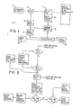
- FIGURE 1 indicates, in block form, an ink jet printing device 7 having an ink jet head 9 incorporated therein.
- Printing devices incorporating an ink jet head i.e. ink jet printers are known and the description herein is therefore limited to the portions of the printer that are used in conjuction with the analyzing system and method described herein.
- ink jet head 9 is connected with a pressurized ink supply 11 through valve 13.
- ink supply 11 is shown to be pressurized, a separate pressure source could be utilized, it being only necessary that a pressure build-up be caused to occur in the ink jet head, in the pressence of ink therein, so that the ink is ejected from the ink jet head to material 15 (commonly paper) to be inked at an ink application area, as is common for printing devices utilizing ink jet heads.
- Valve 13 is preferably an electro-magneticly actuated valve contolled by a valve control unit 17 through a valve driver 19. As is well known, such a valve may be opened by an energizing electrical output signal from the valve control unit applied through the driver (or amplifier) 19-to the valve unit. As indicated in FIGURE 1, the electrical output signal from valve control unit 17 is also coupled to sensing system 21.
- ink jet head 9 has a pressure responsive transducer 23 to sense the pressure build-up within the ink jet head.
- Transducer 23 is preferably a piezoelectric crystal and is preferably the same crystal that is used to excite the ink jet head to break the ink stream into droplets.
- the output from piezoelectric crystal 23 is an electrical signal that is proportional to the transient ink pressure against crystal 23 within the ink jet head. This signal is coupled to sensing system 21 of this invention.
- the amount of time required for pressure to build-up to predetermined levels is determined and outputs indicative thereof are coupled to microcomputer 25 for analysis of operation of the ink jet head (along with the valve mechanism associated therewith).
- the time between initiation of start-up (by providing an output signal from valve control unit 17) and the actual start of pressure build-up in the ink jet head indicates the general condition of the valve mechanism. If this initiation of start time is out of tolerance, microcomputer 25 turns on console light 24 to indicate that the valve mechanism should be checked.
- the general condition of the ink jet head may be determined, as can the likelihood of a clean start of the ink streams ejected from the ink jet head to the material to be inked.
- microcomputer 25 will actuate print control 26 to start a print operation, or to start a self recovery and clean-up procedure for the ink jet head.
- Print control 26, which is not a part of this invention, represents the functions necessary to print including control of relative motion between the ink jet head and the print material, data synchronization and deflection of ink droplets, and self-recovery operations for the ink jet head assembly 9.
- FIGURE 2 illustrates, in block form, an implementation of the sensing system 21 of this invention.
- gate 29 receives the electrical signal from valve control unit 17 as one input thereto.
- Gate 29 also receives a second input from clock 31 at any available clock frequency (for example, at a frequency of 16 MHz).
- valve conrol unit 17 When a signal is coupled from valve conrol unit 17 to energize valve 13 to "open” the valve, the signal is also coupled to gate 29 to gate the clock signal therethrough.
- the output from gate 29 is connected to delay counter 33 and when an output is provided by gate 29, this causes delay counter 33 to start to count at a rate controlled by the frequency of the clock input to gate 29.
- ink jet head 9 As ink passes through valve 13 to ink jet head 9, the pressure in the ink jet head begins to rise.
- the increase in pressure in the ink jet head causes deformation of piezoelectric crystal 23 and this produces a transient electrical output signal (which may be amplified) from the crystal that has a pulse height proportional to pressure.
- Crystal 23 has a frequency response sufficient to be sensitive to'the pressure rise times to be sensed. Examples of rise times to be sensed are described hereinafter in reference to FIGURES 3, 4-and 5.
- a DC pressure transducer separate from piezoelectric crystal 23 might be placed in the ink jet cavity of head 9 to supply the pressure signals for the sensing system 21.
- piezoelectric crystal 23 is preferably also the excitation crystal for drop generation in the ink jet head, crystal 23, as shown in FIGURE 2, is connected to switch 35 for switching the crystal between the two different modes of operation (i.e., excitation of the crystal by means of crystal drive unit 37 and sensing of pressure build-up within the ink jet head) by an external mode control input signal controlling the switch.
- crystal 23 When switch 35 is in the sensing mode (as indicated in FIGURE 2), crystal 23 is connected with comparators 39 and 41 of the sensing system 21 to produce one input thereto. This input to the comparators indicates the amount of pressure build-up in the ink jet head.
- Comparator 39 receives, as a second input, a reference signal, or voltage, just sufficient to indicate the start of rise of pressure within the ink jet head.
- a reference signal or voltage
- the signal coupled to comparator 39 from piezoelectric crystal 23 increases.
- an output is provided at comparator 39, and this output is coupled to delay counter 33 to terminate the count thereat (the count having been started at initiation of start-up by the signal from valve control unit 17 enabling gate 29).
- the output signal from comparator 39 is also coupled to gate 43 as one input thereto.
- Gate 43 receives, as a second input thereto, the clock signal from clock 31 so that when an output is received from comparator 39 (indicating the start of rise of pressure within the ink jet head), the clock signal is gated through gate 43 to rise time counter 45 to cause counter 45 to start to count at a rate determined by the frequency of the clock.
- Piezoelectric crystal 23 is also connected to comparator 41 to couple an input thereto indicative of the pressure within the ink jet head.
- Comparator 41 also receives, as a second input, a second reference level signal, or voltage. This second reference level is greater than the first level coupled to comparator 39 and is selected to be indicative of a level within the ink jet head of almost the supply, or operational, level.
- a second reference level is greater than the first level coupled to comparator 39 and is selected to be indicative of a level within the ink jet head of almost the supply, or operational, level.
- the count on delay counter 33 _ is coupled through logic gate 49 and data bus 51 to delay register 53 of memory 55 in microcomputer 25, which microcomputer also includes a microprocessor 57. This count is stored in delay register 53 and then used to calculate the time delay, or lapse, between switching of valve control unit 17 and the start of pressure rise in the ink jet head.
- the count on rise time counter 45 is coupled through logic gate 59 and data bus 51 to rise time register 61 in memory 55 of microcomputer 25.
- This count represents the rate of pulse rise, i.e., rise time of pressure within the ink jet head.
- address decode unit 63 As shown in FIGURE 2, the transfer of the counts from counters 33 and 45 is controlled by address decode unit 63.
- address decode unit 63 When microprocessor 57 generates the address for delay register 53, address decode unit 63 generates an enable signal for logic gate 49.
- address decode unit 63 When microprocessor 57 generates the address for rise time register 61, address decode unit 63 generates an enable signal for logic gate 59. Gates 49 and 59 transfer the delay count and rise time count to registers 53 and 61, respectively, when enabled.
- the count data can be used, for example, to update statistics in the microprocessor diagnostic logs concerning frequency of valve starts exhibiting similar counts to thereby generate a frequency distribution of start speeds.
- the data, used in conjunction with microprocessor generated statistics on the trend of machine valves, can also indicate impending head-valve failures and is therefore useful in machine maintenance.
- FIGURE 3 is a flow diagram illustrating operation of microprocessor 57. As shown, it is first determined if the data from delay register 53 is equal to or greater than a value X 1 (which is the characteristic valve pick time lower limit and may be, for example, 3 ms). If not, an output is produced to energize an indication (such as console light 24-FIGURE 1) to indicate a need for valve maintenance. At the same time, the valve pick number and delay can be stored in the memory 55.
- X 1 which is the characteristic valve pick time lower limit and may be, for example, 3 ms.
- the indication i.e., light 24 is energized to indicate the need for valve maintenance in the same manner as if the value was less than the value X 1 .
- the data for register 53 is greater than, or equal to, the value X 1 , but is less than the value X 2 , then the data is obtained from time rise register 61. Also, if valve maintenance has been indicated, the microprocessor still obtains the rise time data. If the rise time is within limits, the printing operation can proceed even though the valve operation is out of tolerance.
- the frequency distribution of the rise time is next updated. If the rise time is greater than, or equal to, a value X 3 (which is the rise time upper limit and may be. for example, 5 ms), then the machine is instructed to initiate a self-recovery procedure, after which the start procedure is automatically repeated.
- a value X 3 which is the rise time upper limit and may be. for example, 5 ms
- the machine is instructed to supply ink to the material and thus to start the print operation.
- the machine is delayed by a value Z (which is the delay time required to dissolve unwanted air from the ink in the ink jet head), after which the machine starts to print.
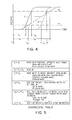
- Waveform A represents a normal start-up where the valve operated within tolerances and the pressure rise time t 2A indicates a proper start-up of the ink jet.
- Waveform B is an example where valve actuation was within tolerance but the pressure build-up is too slow. The likely result of the slow pressure build-up is that ink is sprayed onto the other components in the ink jet head assembly. It is very likely that a successful print operation could not occur and therefore, a recovery procedure would be initiated.
- Waveform C is an example where the start time indicates that valve actuation is out of tolerance, however, once started the pressure rise time build-up is normal. In this situation, a normal print operation could be expected but the valve would be marked for maintenance in anticipation of a future failure.
- the diagnostic table in FIGURE 5 shows the criteria for selecting the values X 1 , X 2 , X3, and X 4 used by the microprocessor 57 as described in the flow diagram of FIGURE 3.
- start time is less than X 1 , or greater than or equal to X 2
- the valve is out of tolerance and a failure of the valve in the future can be expected.
- a rise time of less than X1 might be caused by the valve being out of adjustment or the valve actuation being too short in its stroke in turning ink flow on and off.
- the start time being greater than or equal to X 2 can be an indication that the valve mechanism is slow, possibly because it is dirty. It can also indicate that the electronic drive for the valve solenoid is weak or possibly the solenoid itself is weak. Waveform C in FIGURE 4 is an example of the start time being greater than X 2 .
- Waveform B in FIGURE 4 is an example of a rise time greater than X 3 .
- the rise time being greater or equal to X 4 , but less than X 3 is an indication that the ink pressure build-up in the head was slow but probably not so slow as to cause a wetting of the head assembly during start-up. This may indicate that the ink jet stream would be hard to control but a printing operation can likely proceed successfully.
- One probable cause for the slower than normal rise time is air in the head. By allowing a period of delay before the print operation begins this air can usually be removed by being dissolved into the ink. Of course another source for the slow rise time might be a low ink pressure. In this case the ink stream may be hard to control.
- Waveforms A and C are examples of proper rise times.
- a high count on register 53 can be used to indicate the need for valve maintenance, while a high count on register 61 can leave the machine in a "not ready” mode to dissolve entrapped air and thus insure proper drop generating action.
- the value of the high counts can also be used to initiate discreet levels of machine self-recovery, such as air purging of the head, valve starting re-tries, or deflection electrode cleaning.
- system and method could also be utilized to time the speed of pressure decay in the ink jet head at valve shut-off in the same manner as described hereinabove with respect to start-up. Such information can, of course, also be utilized to determine proper operation of the ink jet head and associated valve mechanisms.
- this invention provides a system and method for automated dynamic analysis of a device such as an ink jet head and can, by way of example, detect a sticking valve, air ingestion during valve cycling, incomplete air purging after head replacement, and/or air leaks in the ink system.
Landscapes
- Ink Jet (AREA)
- Particle Formation And Scattering Control In Inkjet Printers (AREA)
- Spectrometry And Color Measurement (AREA)
- Coating Apparatus (AREA)
Applications Claiming Priority (2)
| Application Number | Priority Date | Filing Date | Title |
|---|---|---|---|
| US971967 | 1978-12-21 | ||
| US05/971,967 US4241406A (en) | 1978-12-21 | 1978-12-21 | System and method for analyzing operation of an ink jet head |
Publications (3)
| Publication Number | Publication Date |
|---|---|
| EP0012821A2 true EP0012821A2 (fr) | 1980-07-09 |
| EP0012821A3 EP0012821A3 (en) | 1981-01-28 |
| EP0012821B1 EP0012821B1 (fr) | 1983-05-18 |
Family
ID=25518995
Family Applications (1)
| Application Number | Title | Priority Date | Filing Date |
|---|---|---|---|
| EP79104374A Expired EP0012821B1 (fr) | 1978-12-21 | 1979-11-08 | Imprimeur d'impression à jet d'encre avec des moyens de surveillance de sa tête |
Country Status (18)
| Country | Link |
|---|---|
| US (1) | US4241406A (fr) |
| EP (1) | EP0012821B1 (fr) |
| JP (1) | JPS5831310B2 (fr) |
| AU (1) | AU527949B2 (fr) |
| BR (1) | BR7908401A (fr) |
| CA (1) | CA1129939A (fr) |
| DE (1) | DE2965464D1 (fr) |
| DK (1) | DK148224C (fr) |
| ES (2) | ES8101279A1 (fr) |
| FI (1) | FI70828C (fr) |
| GR (1) | GR70239B (fr) |
| HU (1) | HU180253B (fr) |
| IL (1) | IL58651A (fr) |
| NO (1) | NO794166L (fr) |
| PL (1) | PL220567A1 (fr) |
| PT (1) | PT70595A (fr) |
| RO (1) | RO77579A (fr) |
| ZA (1) | ZA795962B (fr) |
Cited By (4)
| Publication number | Priority date | Publication date | Assignee | Title |
|---|---|---|---|---|
| EP0221703A1 (fr) * | 1985-10-31 | 1987-05-13 | Ing. C. Olivetti & C., S.p.A. | Tête d'impression à jet d'encre |
| EP0348234A3 (en) * | 1988-06-23 | 1990-05-30 | Canon Kabushiki Kaisha | Ink-jet recording apparatus |
| US5140429A (en) * | 1988-06-23 | 1992-08-18 | Canon Kabushiki Kaisha | Ink-jet recording apparatus with mechanism for automatically regulating a recording head |
| US5927547A (en) * | 1996-05-31 | 1999-07-27 | Packard Instrument Company | System for dispensing microvolume quantities of liquids |
Families Citing this family (17)
| Publication number | Priority date | Publication date | Assignee | Title |
|---|---|---|---|---|
| JPS5818275A (ja) * | 1981-07-28 | 1983-02-02 | Sharp Corp | インクジエツト記録装置 |
| JPS58208063A (ja) * | 1982-05-25 | 1983-12-03 | Yokogawa Hokushin Electric Corp | インクジエツトヘツド |
| JPS597055A (ja) * | 1982-07-05 | 1984-01-14 | Ricoh Co Ltd | インクジエツト記録装置 |
| US4518974A (en) * | 1982-09-21 | 1985-05-21 | Ricoh Company, Ltd. | Ink jet air removal system |
| US4523199A (en) * | 1982-09-29 | 1985-06-11 | Exxon Research & Engineering Co. | High stability demand ink jet apparatus and method of operating same |
| US4670711A (en) * | 1985-02-04 | 1987-06-02 | The Boeing Company | High-speed transient pulse height counter |
| US4797686A (en) * | 1985-05-01 | 1989-01-10 | Burlington Industries, Inc. | Fluid jet applicator for uniform applications by electrostatic droplet and pressure regulation control |
| DE3885238T2 (de) * | 1987-11-27 | 1994-03-03 | Canon Kk | Tintenstrahlaufzeichnungsgerät. |
| JPH02275347A (ja) * | 1989-04-17 | 1990-11-09 | Canon Inc | 熱エネルギーを利用したインクジェットプリンタにおける発泡現象の解析方法 |
| US6203759B1 (en) | 1996-05-31 | 2001-03-20 | Packard Instrument Company | Microvolume liquid handling system |
| US6537817B1 (en) | 1993-05-31 | 2003-03-25 | Packard Instrument Company | Piezoelectric-drop-on-demand technology |
| US6521187B1 (en) | 1996-05-31 | 2003-02-18 | Packard Instrument Company | Dispensing liquid drops onto porous brittle substrates |
| US6276770B1 (en) | 1998-11-17 | 2001-08-21 | Pitney Bowes Inc. | Mailing machine including ink jet printing having print head malfunction detection |
| US6350006B1 (en) | 1998-11-17 | 2002-02-26 | Pitney Bowes Inc. | Optical ink drop detection apparatus and method for monitoring operation of an ink jet printhead |
| US6435642B1 (en) | 1998-11-17 | 2002-08-20 | Pitney Bowes Inc. | Apparatus and method for real-time measurement of digital print quality |
| US6612676B1 (en) | 1998-11-17 | 2003-09-02 | Pitney Bowes Inc. | Apparatus and method for real-time measurement of digital print quality |
| US6782345B1 (en) * | 2000-10-03 | 2004-08-24 | Xerox Corporation | Systems and methods for diagnosing electronic systems |
Family Cites Families (15)
| Publication number | Priority date | Publication date | Assignee | Title |
|---|---|---|---|---|
| JPS5018284Y1 (fr) * | 1970-02-28 | 1975-06-04 | ||
| JPS481446U (fr) * | 1971-05-24 | 1973-01-10 | ||
| US3796630A (en) * | 1971-10-04 | 1974-03-12 | Phillips Petroleum Co | Microbial production of dicarboxylic acids |
| US3925789A (en) * | 1971-12-16 | 1975-12-09 | Casio Computer Co Ltd | Ink jet recording apparatus |
| US3787882A (en) * | 1972-09-25 | 1974-01-22 | Ibm | Servo control of ink jet pump |
| US3831727A (en) * | 1972-11-21 | 1974-08-27 | Ibm | Pressurizing system for ink jet printing apparatus |
| JPS4994341U (fr) * | 1972-12-04 | 1974-08-15 | ||
| US3828172A (en) * | 1973-06-04 | 1974-08-06 | Eastman Kodak Co | Replenishment controller for photographic processors |
| US4085408A (en) * | 1973-09-07 | 1978-04-18 | Minolta Camera Kabushiki Kaisha | Liquid jet recording apparatus |
| US3952759A (en) * | 1974-08-14 | 1976-04-27 | M & J Valve Company | Liquid line break control system and method |
| US3969733A (en) * | 1974-12-16 | 1976-07-13 | International Business Machines Corporation | Sub-harmonic phase control for an ink jet recording system |
| US4029122A (en) * | 1976-03-11 | 1977-06-14 | Westinghouse Electric Corporation | Apparatus and method for determining friction forces in position modulated valves |
| US4131899A (en) * | 1977-02-22 | 1978-12-26 | Burroughs Corporation | Droplet generator for an ink jet printer |
| US4097873A (en) * | 1977-02-28 | 1978-06-27 | International Business Machines Corporation | Ink jet printer for selectively printing different resolutions |
| US4125845A (en) * | 1977-08-25 | 1978-11-14 | Silonics, Inc. | Ink jet print head pressure and temperature control circuits |
-
1978
- 1978-12-21 US US05/971,967 patent/US4241406A/en not_active Expired - Lifetime
-
1979
- 1979-10-31 CA CA338,835A patent/CA1129939A/fr not_active Expired
- 1979-11-06 ZA ZA00795962A patent/ZA795962B/xx unknown
- 1979-11-06 IL IL58651A patent/IL58651A/xx unknown
- 1979-11-08 EP EP79104374A patent/EP0012821B1/fr not_active Expired
- 1979-11-08 DE DE7979104374T patent/DE2965464D1/de not_active Expired
- 1979-11-09 JP JP54144513A patent/JPS5831310B2/ja not_active Expired
- 1979-11-19 AU AU52949/79A patent/AU527949B2/en not_active Ceased
- 1979-12-11 GR GR60725A patent/GR70239B/el unknown
- 1979-12-14 ES ES486891A patent/ES8101279A1/es not_active Expired
- 1979-12-14 PT PT70595A patent/PT70595A/pt unknown
- 1979-12-19 FI FI793993A patent/FI70828C/fi not_active IP Right Cessation
- 1979-12-19 NO NO794166A patent/NO794166L/no unknown
- 1979-12-20 HU HU79IE904A patent/HU180253B/hu not_active IP Right Cessation
- 1979-12-20 RO RO7999626A patent/RO77579A/fr unknown
- 1979-12-20 BR BR7908401A patent/BR7908401A/pt unknown
- 1979-12-20 DK DK547179A patent/DK148224C/da active
- 1979-12-20 PL PL22056779A patent/PL220567A1/xx unknown
-
1980
- 1980-07-28 ES ES493757A patent/ES493757A0/es active Granted
Cited By (8)
| Publication number | Priority date | Publication date | Assignee | Title |
|---|---|---|---|---|
| EP0221703A1 (fr) * | 1985-10-31 | 1987-05-13 | Ing. C. Olivetti & C., S.p.A. | Tête d'impression à jet d'encre |
| EP0348234A3 (en) * | 1988-06-23 | 1990-05-30 | Canon Kabushiki Kaisha | Ink-jet recording apparatus |
| US4977459A (en) * | 1988-06-23 | 1990-12-11 | Canon Kabushiki Kaisha | Ink-jet recording apparatus with mechanism for automatically regulating a recording head |
| US5140429A (en) * | 1988-06-23 | 1992-08-18 | Canon Kabushiki Kaisha | Ink-jet recording apparatus with mechanism for automatically regulating a recording head |
| US5927547A (en) * | 1996-05-31 | 1999-07-27 | Packard Instrument Company | System for dispensing microvolume quantities of liquids |
| US6079283A (en) * | 1996-05-31 | 2000-06-27 | Packard Instruments Comapny | Method for aspirating sample liquid into a dispenser tip and thereafter ejecting droplets therethrough |
| US6083762A (en) * | 1996-05-31 | 2000-07-04 | Packard Instruments Company | Microvolume liquid handling system |
| US6112605A (en) * | 1996-05-31 | 2000-09-05 | Packard Instrument Company | Method for dispensing and determining a microvolume of sample liquid |
Also Published As
| Publication number | Publication date |
|---|---|
| EP0012821B1 (fr) | 1983-05-18 |
| DK547179A (da) | 1980-06-22 |
| CA1129939A (fr) | 1982-08-17 |
| US4241406A (en) | 1980-12-23 |
| GR70239B (fr) | 1982-09-01 |
| JPS5831310B2 (ja) | 1983-07-05 |
| JPS5584676A (en) | 1980-06-26 |
| IL58651A (en) | 1984-03-30 |
| EP0012821A3 (en) | 1981-01-28 |
| ES486891A0 (es) | 1980-12-01 |
| IL58651A0 (en) | 1980-02-29 |
| NO794166L (no) | 1980-06-24 |
| ES8101279A1 (es) | 1980-12-01 |
| FI70828B (fi) | 1986-07-18 |
| HU180253B (en) | 1983-02-28 |
| FI793993A7 (fi) | 1980-06-22 |
| AU527949B2 (en) | 1983-03-31 |
| FI70828C (fi) | 1986-10-27 |
| ES8106807A1 (es) | 1981-08-01 |
| RO77579A (fr) | 1982-12-06 |
| AU5294979A (en) | 1980-06-26 |
| BR7908401A (pt) | 1981-08-18 |
| DE2965464D1 (en) | 1983-07-07 |
| DK148224C (da) | 1985-05-06 |
| DK148224B (da) | 1985-05-06 |
| ZA795962B (en) | 1980-10-29 |
| PL220567A1 (fr) | 1980-08-25 |
| PT70595A (en) | 1980-01-01 |
| ES493757A0 (es) | 1981-08-01 |
Similar Documents
| Publication | Publication Date | Title |
|---|---|---|
| EP0012821A2 (fr) | Imprimeur d'impression à jet d'encre avec des moyens de surveillance de sa tête | |
| US6682162B2 (en) | Printing apparatus with measuring circuit for diagnosis of condition of each electromechanical transducer | |
| US6361138B1 (en) | Ink jet printing apparatus and ink cartridge | |
| US3925789A (en) | Ink jet recording apparatus | |
| EP0221703B1 (fr) | Tête d'impression à jet d'encre | |
| US4540997A (en) | Method and apparatus for avoiding the drying of ink in the ink jets of ink jet printers | |
| EP1378359B1 (fr) | Méthode pour commander une tête d'impression jet d'encre, tête d'impression jet d'encre utilisable avec cette méthode et imprimante jet d'encre comprenant cette tête | |
| JPH0333508B2 (fr) | ||
| EP0026387B1 (fr) | Méthode pour opérer une imprimante à percussion munie d'un détecteur de durée de vol et de vitesse | |
| EP1790484B1 (fr) | Procédé pour augmenter la fiabilité d'une imprimante à jet d'encre et imprimante à jet d'encre appropriée pour l'utilisation du procédé | |
| US4864323A (en) | Continuous ink jet printing | |
| US6062669A (en) | Method for detecting ink cartridge status | |
| JP3486205B2 (ja) | インクジェットヘッドを備えた電子卓上計算機 | |
| JP2001219581A (ja) | インクジェット記録装置 | |
| EP0652831B1 (fr) | Imprimantes a jet d'encre et leurs procedes d'exploitation | |
| US5850236A (en) | Prefiring method for an ink-jet head and apparatus having the ink-jet head with the prefiring method | |
| JP2000203004A (ja) | インクジェット記録装置 | |
| KR100438728B1 (ko) | 프린터의 메인터넌스 제어를 위한 잉크 토출량 검출 장치및 방법 | |
| JPH08281928A (ja) | 印字装置 | |
| US5278765A (en) | Apparatus for monitoring a predetermined treatment effected on objects successively moved along a given path | |
| JP3454859B2 (ja) | インクジェットヘッドを備えた電子卓上計算機 | |
| JP2022002884A (ja) | インクジェット記録装置、ノズルのメンテナンス方法及びプロブラム | |
| JPS58166083A (ja) | ハンマアラーム検出装置 | |
| JPH0474675A (ja) | 記録装置 | |
| JPS62222852A (ja) | インクジエツト記録装置の溶剤残量検知装置 |
Legal Events
| Date | Code | Title | Description |
|---|---|---|---|
| PUAI | Public reference made under article 153(3) epc to a published international application that has entered the european phase |
Free format text: ORIGINAL CODE: 0009012 |
|
| AK | Designated contracting states |
Designated state(s): BE CH DE FR GB IT NL SE |
|
| PUAL | Search report despatched |
Free format text: ORIGINAL CODE: 0009013 |
|
| AK | Designated contracting states |
Designated state(s): BE CH DE FR GB IT NL SE |
|
| 17P | Request for examination filed |
Effective date: 19801216 |
|
| ITF | It: translation for a ep patent filed | ||
| GRAA | (expected) grant |
Free format text: ORIGINAL CODE: 0009210 |
|
| AK | Designated contracting states |
Designated state(s): BE CH DE FR GB IT NL SE |
|
| PG25 | Lapsed in a contracting state [announced via postgrant information from national office to epo] |
Ref country code: NL Effective date: 19830518 |
|
| REF | Corresponds to: |
Ref document number: 2965464 Country of ref document: DE Date of ref document: 19830707 |
|
| ET | Fr: translation filed | ||
| NLV1 | Nl: lapsed or annulled due to failure to fulfill the requirements of art. 29p and 29m of the patents act | ||
| PLBE | No opposition filed within time limit |
Free format text: ORIGINAL CODE: 0009261 |
|
| STAA | Information on the status of an ep patent application or granted ep patent |
Free format text: STATUS: NO OPPOSITION FILED WITHIN TIME LIMIT |
|
| 26N | No opposition filed | ||
| PGFP | Annual fee paid to national office [announced via postgrant information from national office to epo] |
Ref country code: BE Payment date: 19901005 Year of fee payment: 12 |
|
| PGFP | Annual fee paid to national office [announced via postgrant information from national office to epo] |
Ref country code: GB Payment date: 19901012 Year of fee payment: 12 |
|
| PGFP | Annual fee paid to national office [announced via postgrant information from national office to epo] |
Ref country code: SE Payment date: 19901018 Year of fee payment: 12 |
|
| PGFP | Annual fee paid to national office [announced via postgrant information from national office to epo] |
Ref country code: FR Payment date: 19901020 Year of fee payment: 12 |
|
| PGFP | Annual fee paid to national office [announced via postgrant information from national office to epo] |
Ref country code: DE Payment date: 19901124 Year of fee payment: 12 |
|
| ITTA | It: last paid annual fee | ||
| PGFP | Annual fee paid to national office [announced via postgrant information from national office to epo] |
Ref country code: CH Payment date: 19910225 Year of fee payment: 12 |
|
| PG25 | Lapsed in a contracting state [announced via postgrant information from national office to epo] |
Ref country code: GB Effective date: 19911108 |
|
| PG25 | Lapsed in a contracting state [announced via postgrant information from national office to epo] |
Ref country code: SE Effective date: 19911109 |
|
| PG25 | Lapsed in a contracting state [announced via postgrant information from national office to epo] |
Ref country code: CH Effective date: 19911130 Ref country code: BE Effective date: 19911130 |
|
| BERE | Be: lapsed |
Owner name: INTERNATIONAL BUSINESS MACHINES CORP. Effective date: 19911130 |
|
| GBPC | Gb: european patent ceased through non-payment of renewal fee | ||
| PG25 | Lapsed in a contracting state [announced via postgrant information from national office to epo] |
Ref country code: FR Effective date: 19920731 |
|
| REG | Reference to a national code |
Ref country code: CH Ref legal event code: PL |
|
| PG25 | Lapsed in a contracting state [announced via postgrant information from national office to epo] |
Ref country code: DE Effective date: 19920801 |
|
| REG | Reference to a national code |
Ref country code: FR Ref legal event code: ST |
|
| EUG | Se: european patent has lapsed |
Ref document number: 79104374.8 Effective date: 19920604 |